Ed Nisley's Blog: Shop notes, electronics, firmware, machinery, 3D printing, laser cuttery, and curiosities. Contents: 100% human thinking, 0% AI slop.
Category: Software
General-purpose computers doing something specific
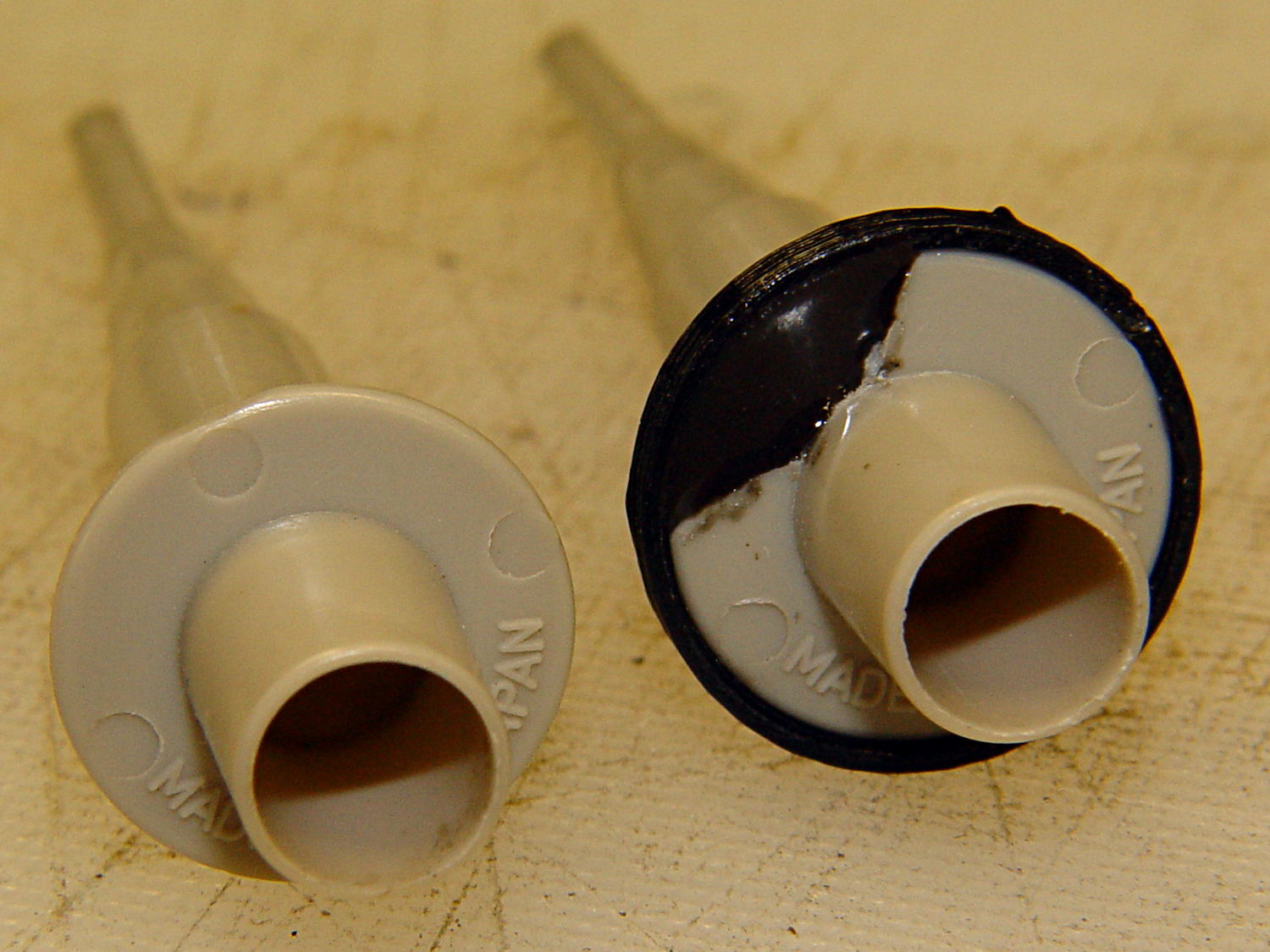
Quite some time ago I manage to break the finger flange on one of my scope probes and, what with it being made of an un-glueable engineering plastic, a simple repair job failed quickly. It’s entirely round and a perfect lathe project, but … this is easier:
HP Scope Probe Flange Repair
You can see remnants of that failed repair just below the fracture:
HP scope probe flanges – repair disk
Some epoxy around the rim of the flange, plus filling the missing sector, looks about as grubby as you’d expect:
HP Scope Probes – rear
That’s a tiny zit at about 1 o’clock which came off with fingernail pressure.
From the business end, it actually looks pretty snappy:
HP Scope Probes – front
I’m mildly tempted to preemptively reinforce the other probes…
The OpenSCAD source code joins two parts with coincident faces, but it worked out OK for once:
// Tek Scope Probe Flange
// Ed Nisley KE4ZNU November 2013

//- Extrusion parameters must match reality!
//  Print with 2 shells and 3 solid layers

ThreadThick = 0.25;
ThreadWidth = 0.40;

HoleWindage = 0.2;

Protrusion = 0.1;			// make holes end cleanly

function IntegerMultiple(Size,Unit) = Unit * ceil(Size / Unit);

//----------------------
// Dimensions

FlangeOD = 16.0;
FlangeID = 8.75;
FlangeThick = IntegerMultiple(1.25,ThreadThick);

DiskOD = FlangeOD + 4*ThreadWidth;
DiskThick = FlangeThick + 4*ThreadThick;

NumSides = 8*4;

//----------------------
// Useful routines

module PolyCyl(Dia,Height,ForceSides=0) {			// based on nophead's polyholes

  Sides = (ForceSides != 0) ? ForceSides : (ceil(Dia) + 2);

  FixDia = Dia / cos(180/Sides);

  cylinder(r=(FixDia + HoleWindage)/2,
           h=Height,
	   $fn=Sides);
}

module ShowPegGrid(Space = 10.0,Size = 1.0) {

  Range = floor(50 / Space);

	for (x=[-Range:Range])
	  for (y=[-Range:Range])
		translate([x*Space,y*Space,Size/2])
		  %cube(Size,center=true);

}

//----------------------
// Build it

ShowPegGrid();

	difference() {
		union() {
			translate([0,0,2*ThreadThick])
				cylinder(r=DiskOD/2,h=DiskThick,$fn=NumSides);			// main repair part
			cylinder(r1=(DiskOD - 2*ThreadWidth)/2,r2=DiskOD/2,h=2*ThreadThick,$fn=NumSides);
		}
		translate([0,0,(DiskThick - FlangeThick)])				// flange clearance
			PolyCyl(FlangeOD,2*FlangeThick,NumSides);
		translate([0,0,-DiskThick/2])
			PolyCyl(FlangeID,2*DiskThick,NumSides);
	}
I’ve been working on an object (more on this later) that requires precise alignment of two parts that capture a nut deep inside. This calls for alignment pins, similar to the ones I used for, say, the Triple-Cylinder Thing:
Cylinder Thing – rotated
The general idea is to design holes that fit the pins, then locate them at the parting line of the model, where they’re subtracted from the solid and appear in exactly the proper places when the model splits for printing:
Cylinder Thing – alignment pegs
You slather solvent glue on both halves, jam pins into the holes, slap the parts together, and clamp until cured. Works fine, I use pins all over the place.
The gotcha of using just a (polygonal) cylinder as the hole: if you glue one end of the pin at a time, a small rim of dissolved plastic may form around the pin at the surface. That can bond the two halves together or prevent them from joining properly after being disassembled.
Sooo, here’s a new alignment pin hole with a gutter around the pin on both surfaces to capture the glop:
Alignment pin hole – overview
Remember, that’s the negative volume that will hold the pin, not the pin itself!
Here’s how it works in real plastic, with a 1.75 mm peg glued into one hole with a bit of crud in the gutter:
Alignment Hole and Pin
The secret to making the gutter work: offset the second layer by half the thread width, so that it’s reasonably well supported on the first layer. If you don’t do that, the inner layers simply drop down through the hole and fill the gutter. Even doing that, notice the distortion of the first few layers inside the hole.
The OpenSCAD source code looks about like you’d expect:
Ideally, the pin length should extend at least two diameters into each side of the object, but you can feed in whatever you need to make it come out right.
The PolyCyl() routine produces a low-vertex-count polygon that circumscribes the nominal diameter, which is what you need for vertical holes in 3D printed objects:
module PolyCyl(Dia,Height,ForceSides=0) {			// based on nophead's polyholes

  Sides = (ForceSides != 0) ? ForceSides : (ceil(Dia) + 2);

  FixDia = Dia / cos(180/Sides);

  cylinder(r=(FixDia + HoleWindage)/2,
           h=Height,
	   $fn=Sides);
}
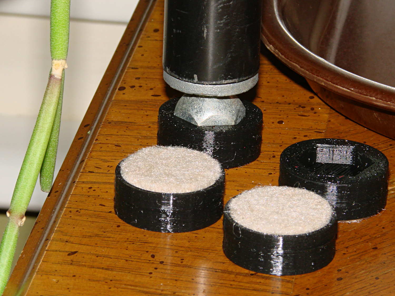
The houseplants have migrated indoors after spending a summer charging up in the sun on the patio, which means it’s time to replace the silicone rubber feet on the bottom of the plant shelves. This year, I printed a set of feet to fit the hex-head adjustable feet:
Plant Stand Foot – installed
The pencil-stem plant on the left, for whatever it’s worth, is a perfectly healthy Rhipsalis that greatly enjoyed the summer sun.
The feet print upside-down to give the surface around the hex a smooth finish. I used Slic3r’s Hilbert Curve for pattern a bit more interesting than the usual parallel lines:
Plant Shelf Foot – as built
The Hilbert curve doesn’t fit neatly into a non-rectangular shape, but it’s close enough.
The solid model includes the support structure:
Plant Shelf Foot – solid model – bottom
Which pops out cleanly:
Plant Shelf Foot – support material detail
Yes, that’s a shred of red filament embedded on the left side. Cleanliness is next to impossible…
The fuzzy felt feet come from a 6 mm thick slab of the stuff:
Plant Shelf Foot – cutting felt plugs
The round socket wall leaves about 2 mm of felt showing at the bottom; it’s not very compressible and that should suffice to keep the plastic off the table.
The OpenSCAD source code:
// Feet for a wire-shelf plant stand
// Ed Nisley KE4ZNU October 2013

Layout = "Build";			// Show Build

Support = true;

//- Extrusion parameters must match reality!
//  Print with 2 shells and 3 solid layers

ThreadThick = 0.25;
ThreadWidth = 0.40;

HoleWindage = 0.2;

Protrusion = 0.1;			// make holes end cleanly

//----------------------
// Dimensions

StandFootOD = 18.0;			// hex across flats
StandFootDepth = 5.0;		//  ... socket depth

FeltPadOD = 25.0;			// felt foot diameter
FeltPadDepth = 4.0;			//  ... depth

FootBaseThick = 6*ThreadThick;	// between foot and pad
FootWall = 4*ThreadWidth;		// around exterior

FootOD = 2*FootWall + max(StandFootOD,FeltPadOD);
echo(str("Foot OD: ",FootOD));

FootTall = StandFootDepth + FootBaseThick + FeltPadDepth;
echo(str(" ... height: "),FootTall);

NumSides = 8*4;

//----------------------
// Useful routines

module FootPad() {

	difference() {

		cylinder(r=FootOD/2,h=FootTall,$fn=NumSides);

		translate([0,0,FeltPadDepth + FootBaseThick])
			PolyCyl(StandFootOD,2*StandFootDepth,6);

		translate([0,0,-Protrusion])
			PolyCyl(FeltPadOD,(FeltPadDepth + Protrusion),NumSides);

	}
}

// Locating pin hole with glue recess

module LocatingPin() {

	translate([0,0,-ThreadThick])
		PolyCyl((PinOD + 2*ThreadWidth),2*ThreadThick,4);
	translate([0,0,-(PinLength/2 + ThreadThick)])
		PolyCyl(PinOD,(PinLength + 2*ThreadThick),4);

}

module PolyCyl(Dia,Height,ForceSides=0) {			// based on nophead's polyholes

  Sides = (ForceSides != 0) ? ForceSides : (ceil(Dia) + 2);

  FixDia = Dia / cos(180/Sides);

  cylinder(r=(FixDia + HoleWindage)/2,
           h=Height,
	   $fn=Sides);
}

module ShowPegGrid(Space = 10.0,Size = 1.0) {

  Range = floor(50 / Space);

	for (x=[-Range:Range])
	  for (y=[-Range:Range])
		translate([x*Space,y*Space,Size/2])
		  %cube(Size,center=true);

}

//-------------------
// Build it...

ShowPegGrid();

if (Layout == "Show")
	FootPad();

if (Layout == "Build") {
	translate([0,0,FootTall])
		rotate([180,0,0])
			FootPad();
	if (Support)
		color("Yellow")
			for (Seg=[0:5]) {
				rotate(30 + 360*Seg/6)
				translate([0,0,(StandFootDepth - ThreadThick)/2])
					cube([(StandFootOD - 3*ThreadWidth),
						  2*ThreadWidth,
						  (StandFootDepth - ThreadThick)],
						  center=true);
				}
}
The Makergear M2 comes with a plastic block that covers the X-min switch wiring and anchors the end of the filament guide. Because the guide wasn’t anchored to the block, bumping the guide tended to bend the filament where it exited the block. To prevent that, I hot-melt-glued the guide to the block, which really wasn’t particularly elegant. This picture shows the X-min switch relocated to contact the platform, with the slightly out of focus blob anchoring the guide off to the right:
M2 – Z-min switch at rear X gantry
Makergear provides STL files of the M2’s printable bits, including several versions of the wire cover block. This corresponds to the one on my M2, although the rounded edges don’t come through in the plastic very welll:
Stock M2 Wire Cover Filament Guide – solid model
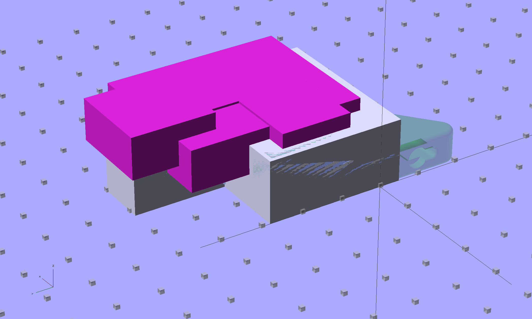
Because STL files aren’t editable, I reverse-engineered the dimensions into an OpenSCAD model that I could use as the basis for a different guide. This is just the basic wire cover, minus the filament guide extension, plus a flat end that wraps around the edge of the chassis:
M2 Wire Cover – reverse engineered
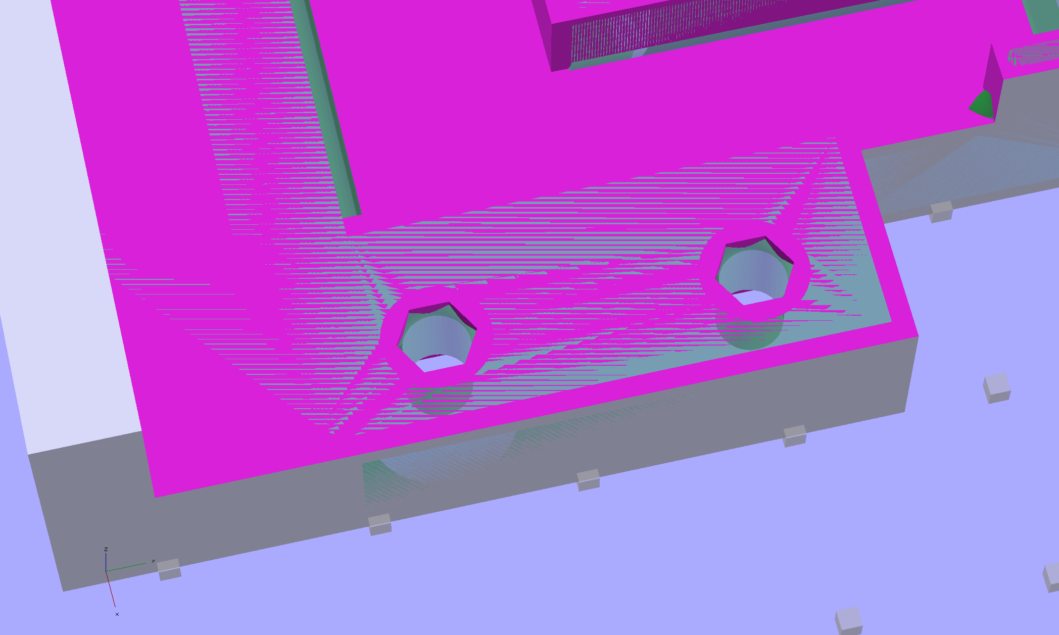
The trick is to import the STL into OpenSCAD, then build a model that matches the key dimensions. Fortunately, Makergear used hard metric sizes for everything, so most of the numbers came out as integers or single-place decimals:
The shimmer indicates coincident surfaces; that’s ordinarily a Very Bad Thing, but in this case it shows that the dimensions match. The top of the holes have neat hexagonal patterns where my straight-sided PolyHoles extend through their chamfered circular holes:
Unlike my from-scratch OpenSCAD models, this one bristles with magic numbers that describe the dimensions of the M2 STL model. The basic shape comes from an extruded polygon matching the outside walls, another extruded polygon knocking out the wire channel, then cubes lopping off the top surfaces:
M2 Wire Cover Filament Guide – overlay – F12 view
The end result of all that thrashing around has a certain Soviet Concrete look to it:
M2 Wire Cover – OpenSCAD solid model
This version lacks the filament guide; I wanted to make sure all the protrusions and channels fit, which they sort of did:
M2 reverse engineered wire cover – installed
The next version will have slightly more clearance on the side and slightly less on the top; that’s easy to do now that I have an editable OpenSCAD model.
The OpenSCAD source code:
// Improved M2 filament guide and X-min switch wire guide
// Ed Nisley KE4ZNU - Oct 2013

function IntegerMultiple(Size,Unit) = Unit * ceil(Size / Unit);

Protrusion = 0.1;

HoleWindage = 0.2;

//- Sizes

PlateMinThick = 8.0;				// basic thickness excluding wire guides
PlateLength = 5.0;					// from side of frame beyond top wire guide

TopGuideLength = 7.0;				// protrusion from plate

PlateThick = PlateMinThick + TopGuideLength;

echo(str("Total thickness: ",PlateThick));

//- Adjust hole diameter to make the size come out right

module PolyCyl(Dia,Height,ForceSides=0) {			// based on nophead's polyholes

  Sides = (ForceSides != 0) ? ForceSides : (ceil(Dia) + 2);

  FixDia = Dia / cos(180/Sides);

  cylinder(r=(FixDia + HoleWindage)/2,h=Height,$fn=Sides);
}

//- Put peg grid on build surface

module ShowPegGrid(Space = 10.0,Size = 1.0) {

  RangeX = floor(100 / Space);
  RangeY = floor(125 / Space);

	for (x=[-RangeX:RangeX])
	  for (y=[-RangeY:RangeY])
		translate([x*Space,y*Space,Size/2])
		  %cube(Size,center=true);

}

//- Define basic block shape
//  Mostly reverse engineered from
//    https://github.com/MakerGear/M2/blob/master/Printed%20Parts/STL/M2%20X%20Endstop%20Wire%20Cover%20with%20Filament%20Guide.stl
//	Hence all the magic numbers...

module BaseBlock() {

SideGuideLength = 4.0;				// protrusion = even with frame interior
ChannelDepth = 4.5;					// wiring channel
FrameOffset = 28;

	translate([18,FrameOffset,0]) {			// align neatly for later processing

		if (true)
			color("Green",0.3)
				translate([-18,22,15])
					rotate([-90,0,-90])
						import("/mnt/bulkdata/Project Files/Thing-O-Matic/M2 Parts/Filament Guide/M2+X+Endstop+Wire+Cover+with+Filament+Guide.stl",
								convexity=10);

		difference() {
			linear_extrude(height=PlateThick,convexity=5)		// main block
				polygon(points=[[0,0],[0,22],[12,22],[12,7.5],[22,7.5],
								[22,-(PlateLength + FrameOffset)],[-18,-(PlateLength + FrameOffset)],
								[-18,0]
						]);

			for (i=[-1,0])
				translate([17,((i*15.0)+ 1.05),-Protrusion])
					rotate(180/6) {
						PolyCyl(3.1,(PlateMinThick + 2*Protrusion),6);		// screw holes
						PolyCyl(5.7,(3.0 + Protrusion),6);					//  ... countersink
					}

			translate([0,0,(PlateMinThick - ChannelDepth)])		// wire channel
				linear_extrude(height=15,convexity=5)
					polygon(points=[[2,-5],[2,19],[10,19],[10,-22],[-15,-22],[-15,-5]
							]);

			translate([-10,14,PlateMinThick])				// M2 frame
				rotate(-90)
					cube([42,35,10],center=false);

			translate([-5,5,(PlateMinThick + SideGuideLength)])	// shorten side guide
				cube([20,20,10],center="false");

		}
	}

}

//- Build it

ShowPegGrid();

BaseBlock();
Fairly obviously, taping the Z-min switch to the back of the X gantry isn’t a long-term solution. There’s just enough clearance between the extruder and the X gantry for the switch, so I made a small block with clearance holes for the screws holding the X axis linear slide rail in place and tapping holes for the M2.5×0.45 screws in the switch:
Z-min Front Mount Switch Block – solid model
Not much to it, is there? That printed just fine with the taped-in-place switch and exactly fit the screws; the rail screws dropped right through the holes and the switch screws tapped their way in.
The stock M2 cable reaches to the front of the X gantry, but only with the switch mounted to the left side:
M2 Z-min switch – left gantry
Those are 25 mm M3 screws shortened to about 19 mm; the one on the right looks a bit short to me, too.
Unfortunately, that spot on the gantry is the only place you can pick up the M2 with one hand: it balances perfectly when you (well, I) put four fingers between the five leftmost rail screws. It’s a beast to carry any other way, so that switch had to move.
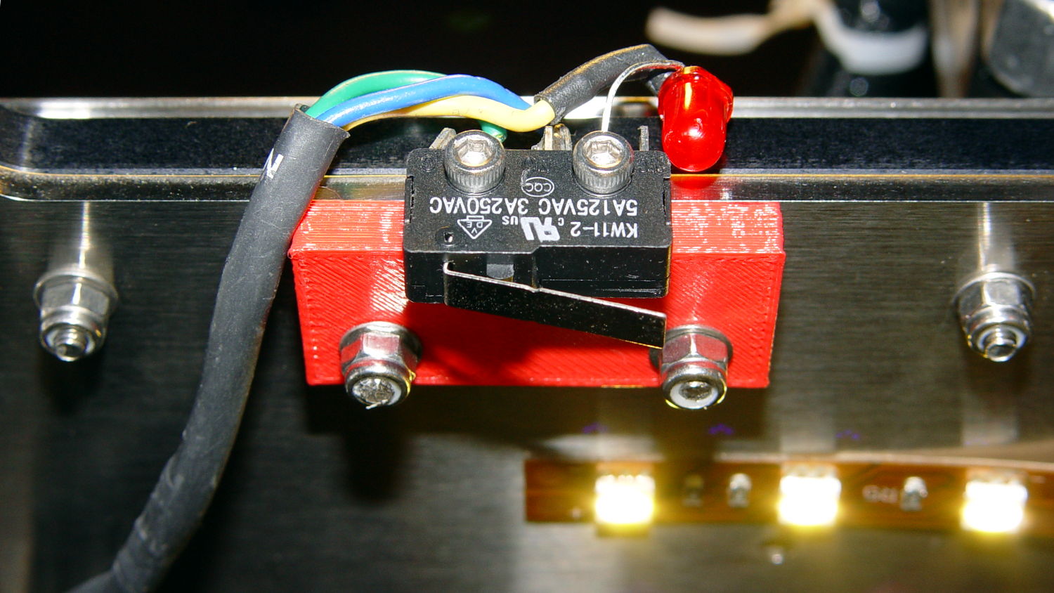
So I spliced in a snippet of six conductor cable, just so I could match the original color code, replaced the red through-hold LED with a blue SMD LED, and moved it to the middle of the gantry:
M2 Z-min switch – center gantry
The view from below shows a sticky clamp holding a bight of the original cable and a small clamp (bent & drilled from a steel strap) holding the new cable in place:
M2 Z-min switch – center gantry – bottom view
It’s once again possible to grab the printer and lug it away…
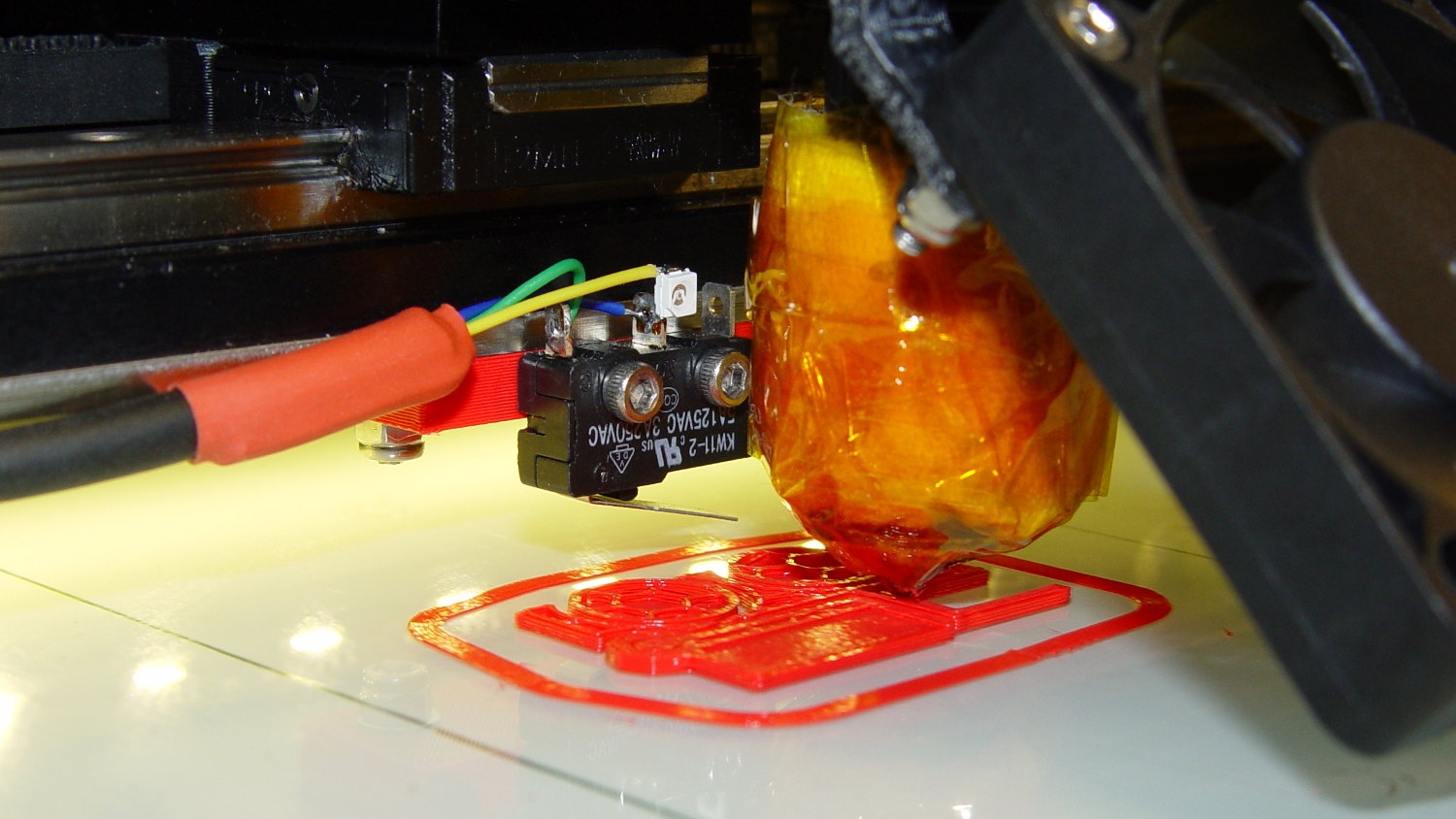
The first test piece was Madscifi’s classic Tiny Toy Dump Truck, because I needed a show-n-tell tchotchke for a Squidwrench meeting:
M2 Z-min switch – center gantry – in action
Yes, that dangling switch lever looks precarious, but it can’t touch the platform because the nozzle is below it.
With the switch in place, I melted a blob of solder atop the brass tubing on the platform, popped it off, and removed the residue with a razor scraper.
Before doing the truck, however, I had to recalibrate the Z switch and make the homing sequence do a different dance:
Home Y and leave the platform at the rear
Home X and move it to the far right to clear the platform
Home Z against the platform glass
The complete start.gcode sequence (which isn’t really a separate file in Slic3r, but the notation helps keep things straight):
;-- Slic3r Start G-Code for M2 starts --
;  Ed Nisley KE4NZU - 7 Oct 2013
; Z-min switch at platform, must move nozzle to X=130 to clear platform
M140 S[first_layer_bed_temperature]	; start bed heating
G90				; absolute coordinates
G21				; millimeters
M83				; relative extrusion distance
M84				; disable stepper current
;G4 S3			; allow Z stage to freefall to the floor
G28 Y0			; home Y to be sure of clearing probe point in X
G92 Y-127 		; set origin to 0 = center of plate
G28 X0			; home X
G92 X-95		; set origin to 0 = center of plate
G1 X130 F30000	; move off platform to right side
G28 Z0			; home Z
G92 Z-4.55		; set origin to measured z offset
G0 Z10 F2000    ; get nozzle clearance
G0 X0 Y-124 Z3.0 F20000     ; set up for priming
M190 S[first_layer_bed_temperature]	; wait for bed to finish heating
M109 S[first_layer_temperature]	; set extruder temperature and wait
G1 Z0.0 F2000	; plug extruder on plate
G1 E10 F300		; prime to get pressure
G1 Z5 F2000		; rise above blob
G1 X5 Y-123 F30000	; move away from blob
G1 Z0.0 F2000		; dab nozzle to remove outer snot
G4 P1			; pause to clear
G1 Z0.5 F2000		; clear bed for travel
;-- Slic3r Start G-Code ends --
The G92 Z-4.55 instruction sets the Z position (without moving the stage) to the measured difference between the switch trip point and the nozzle tip.
Finding that value is a two-step process:
Manually home Z against the platform (with the nozzle off to the right!)
Issue G92 Z0 to define the switch trip point as Z=0.0
Move the Z stage downward by a known distance so it clears the nozzle
Move the nozzle over the platform
Measure the distance between nozzle and platform (perhaps with a tapered gauge)
Subtract that measurement from the distance you moved the nozzle
For example, I lowered the platform by 7.0 mm and measured 2.6 mm between the nozzle and the platform, so the G92 value = -7.0 + 2.6 = -4.4. Put that in the start.gcode G92 instruction: G92 Z-4.4.
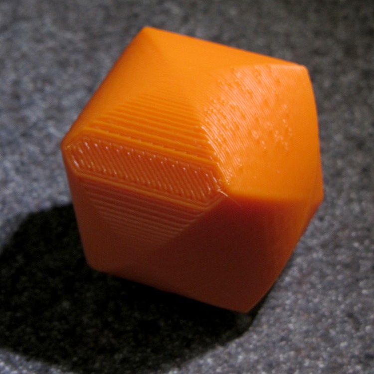
That’ll get you in the ballpark, so print a thinwall open box and measure its top-to-bottom height at the corners. The second box came out about 4.85 mm tall, which means the nozzle was 0.15 mm too close to the platform: subtract 0.15 from the G92 setting: -4.4 – 0.15 = -4.55.
The next thinwall box came out exactly 5.0 mm tall.
Then I could print that truck, which came out just fine, apart from the usual slight drooping where the filament must bridge the left side of the dump box:
M2 Tiny Toy Dump Truck test piece
After breaking one errant strand from the left side of the hinge, everything moved smoothly.
I must tinker up some G-Code to measure the switch closure point along the length of the platform, which would detect front-to-back tilt.
The OpenSCAD source code for the switch mounting block:
// Block to mount M2 Z-min switch on X gantry
// Ed Nisley KE4ZNU - Oct 2013

//- Extrusion parameters - must match reality!

ThreadThick = 0.25;
ThreadWidth = 0.40;

function IntegerMultiple(Size,Unit) = Unit * ceil(Size / Unit);

Protrusion = 0.1;

HoleWindage = 0.2;

//- Sizes

SwitchScrewOD = 2.05;					// microswitch screw tapping
SwitchScrewOC = 9.5;					//  ... on-center spacing

GantryScrewOD = 3.0;					// X rail screw clearance
GantryScrewOC = 25.0;					//  ... on-center spacing along X
GantryScrewOffset = 12.0;				//  ... Y offset from gantry front

BlockSize = [1.5*GantryScrewOC,17.0,5.0];			// XYZ dimensions as mounted

SwitchScrewLength = BlockSize[1] - 5*ThreadWidth;	// net length of switch screws
echo ("Max switch screw length: ",SwitchScrewLength + 5.0);		// ... allow switch thickness

//- Adjust hole diameter to make the size come out right

module PolyCyl(Dia,Height,ForceSides=0) {			// based on nophead's polyholes

  Sides = (ForceSides != 0) ? ForceSides : (ceil(Dia) + 2);

  FixDia = Dia / cos(180/Sides);

  cylinder(r=(FixDia + HoleWindage)/2,h=Height,$fn=Sides);
}

//- Put peg grid on build surface

module ShowPegGrid(Space = 10.0,Size = 1.0) {

  RangeX = floor(100 / Space);
  RangeY = floor(125 / Space);

	for (x=[-RangeX:RangeX])
	  for (y=[-RangeY:RangeY])
		translate([x*Space,y*Space,Size/2])
		  %cube(Size,center=true);

}

//- Build it

ShowPegGrid();

difference() {
	translate([-BlockSize[0]/2,-GantryScrewOffset,0])
		cube(BlockSize,center=false);
	for (i=[-1,1]) {
		translate([i*GantryScrewOC/2,0,-Protrusion])
			rotate(-90)
				PolyCyl(GantryScrewOD,(BlockSize[2] + 2*Protrusion));
		translate([i*SwitchScrewOC/2,-(GantryScrewOffset + Protrusion),BlockSize[2]/2])
			rotate([-90,0,0])
				rotate(90)
					PolyCyl(SwitchScrewOD,(SwitchScrewLength + Protrusion));
	}
}
This may not look like much, but it’s the first test of the p-MOSFET power switch that completely kills power to the Arduino Pro Mini board and the Hall Effect LED Blinky Light:
Power off – 30 mA load
The top trace is the base drive to the NPN transistor that holds the p-MOSFET on while the Arduino is running. When it’s time to shut off, the Arduino drops the base drive output, the MOSFET turns off, and the switched battery voltage in the bottom trace drops like a rock. The current is about 30 mA when the Arduino is running and immeasurably low when it’s off; the MOSFET spec says it’s less than 1 μA, which is fine with me.
The PCB has those components clustered in the upper left corner, with the Arduino Pro Mini perched on header pins to the right:
Hall LED PCB – power switch test
The test code is a crudely hacked version of the canonical Blink sketch that waits 5 s after it starts running, then pulls the plug:
// Modified from Arduino Blink example
// Drives external p-MOSFET power switch
// Ed Nisley - KE4ZNU - Sep 2013

int led = 13;

// HIGH to enable power supply
int PowerOn = 4;

// HIGH to light Status LED
int Status = 10;

unsigned long MillisThen;

void setup() {

  pinMode(led, OUTPUT);

  pinMode(PowerOn,OUTPUT);
  digitalWrite(PowerOn,HIGH);
  pinMode(Status,OUTPUT);
  digitalWrite(Status,HIGH);

MillisThen = millis();
}

void loop() {
  digitalWrite(led, HIGH);
  delay(100);
  digitalWrite(led, LOW);
  delay(500);

  if (((millis() - MillisThen) > 5000ul)) {
      digitalWrite(Status,LOW);
      delay(50);
      digitalWrite(PowerOn,LOW);
      digitalWrite(Status,HIGH);
  }
}
It turns out that the Arduino runtime has a several-second delay after power comes up before the setup() routine starts running, so brief pulses from a vibration switch won’t last long enough to turn the thing on. That’s not a fatal flaw for now and, in fact, having to hold the power button in for a few seconds isn’t entirely a Bad Thing.
However, once the power turns on, a vibration switch could trigger an Arduino interrupt pin to reset a power-off timer. I’d be tempted to put the vibration switch in parallel with the button, with a pair of steering diodes that isolate the raw battery from the input pin.
This is, of course, a pure electronic implementation of a Useless Machine…
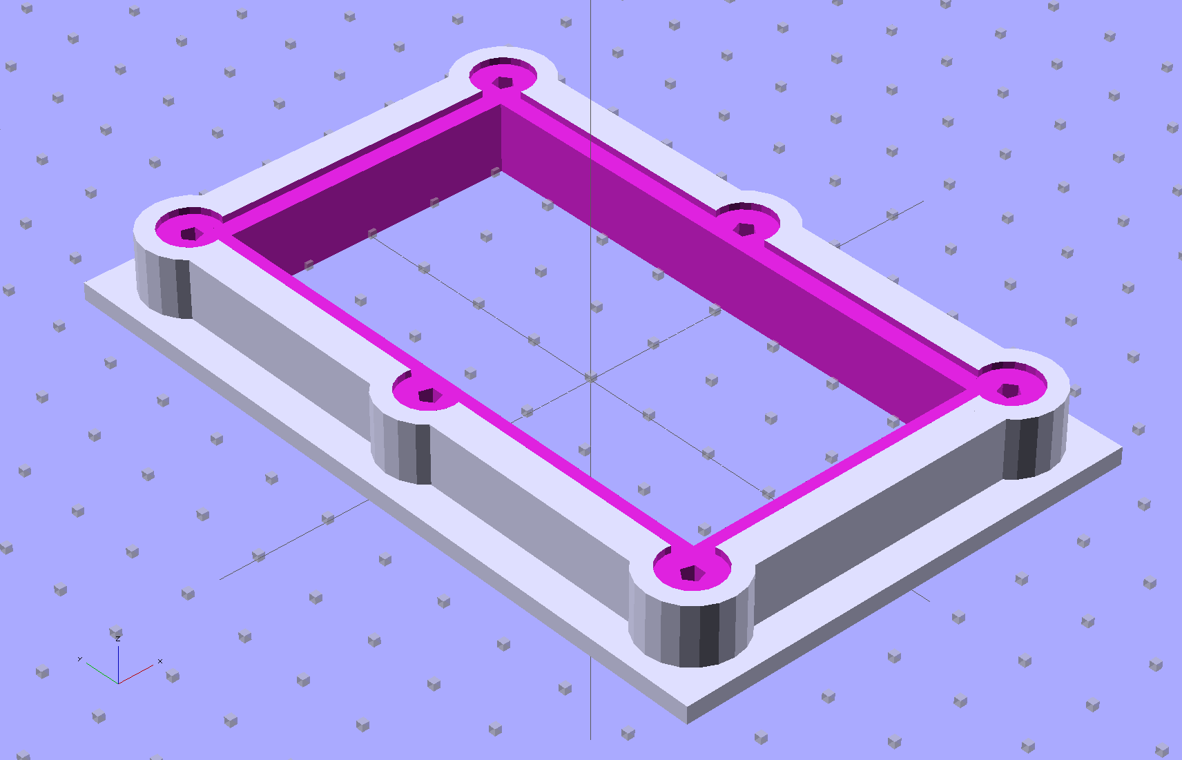
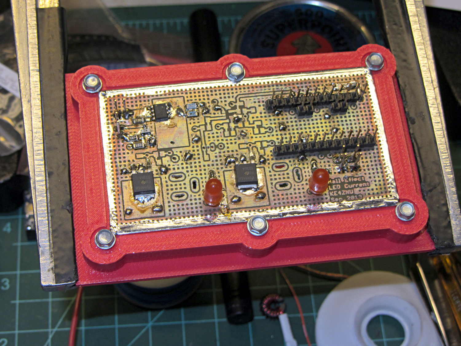
The brassboard PCB for the Hall effect blinky light is too bendy for the SMD parts to survive much debugging, particularly with all the wires hanging off the edges, so I whipped up a stiff mounting bracket that captures the whole thing, with a flange that fits in the work stand arms:
PCB Test Frame – solid model
I ran some self-tapping 4-40 hex-head screws into the holes while the plastic was still warm on the M2’s platform:
PCB stiffener with screws on M2 platform
Six screws seem excessive and I’ll probably wind up using just the middle two, but there’s no harm in having more holes and fittings than you really need.
The flange fits neatly into the board holder on the Electronics Workbench, above all the construction clutter:
PCB stiffener in board holder
The nice thing about having a 3D printer: when you need an object like this, a couple of hours later you have one!
The OpenSCAD source code, slightly improved based the results you see above:
// Test support frame for Hall Effect LED Blinky Light
// Ed Nisley KE4ZNU - Sept 2013

ClampFlange = true;

//- Extrusion parameters - must match reality!

ThreadThick = 0.25;
ThreadWidth = 0.40;

function IntegerMultiple(Size,Unit) = Unit * ceil(Size / Unit);

Protrusion = 0.1;

HoleWindage = 0.2;

//- Screw sizes

inch = 25.4;

Tap4_40 = 0.089 * inch;
Clear4_40 = 0.110 * inch;
Head4_40 = 0.211 * inch;
Head4_40Thick = 0.065 * inch;
Nut4_40Dia = 0.228 * inch;
Nut4_40Thick = 0.086 * inch;
Washer4_40OD = 0.270 * inch;
Washer4_40ID = 0.123 * inch;

//- PCB sizes

PCBSize = [46.5,84.0,1.0];
PCBShelf = 2.0;

Clearance = 4*[ThreadWidth,ThreadWidth,0];

WallThick = IntegerMultiple(4.0,ThreadWidth);
FrameHeight = 5.0;

ScrewOffset = 0.0 + Clear4_40/2;

OAHeight = FrameHeight + Clearance[2] + PCBSize[2];

FlangeExtension = 3.0;
FlangeThick = IntegerMultiple(1.5,ThreadThick);
Flange = PCBSize
			+ 2*[ScrewOffset,ScrewOffset,0]
			+ 2*[Washer4_40OD,Washer4_40OD,0]
			+ [2*FlangeExtension,2*FlangeExtension,(FlangeThick - PCBSize[2])]
			;

echo("Flange: ",Flange);
NumSides = 4*5;

//- Adjust hole diameter to make the size come out right

module PolyCyl(Dia,Height,ForceSides=0) {			// based on nophead's polyholes

  Sides = (ForceSides != 0) ? ForceSides : (ceil(Dia) + 2);

  FixDia = Dia / cos(180/Sides);

  cylinder(r=(FixDia + HoleWindage)/2,h=Height,$fn=Sides);
}

//- Put peg grid on build surface

module ShowPegGrid(Space = 10.0,Size = 1.0) {

  RangeX = floor(100 / Space);
  RangeY = floor(125 / Space);

	for (x=[-RangeX:RangeX])
	  for (y=[-RangeY:RangeY])
		translate([x*Space,y*Space,Size/2])
		  %cube(Size,center=true);

}

//- Build it

ShowPegGrid();

difference() {
	union() {									// body block and screw bosses
		translate([0,0,OAHeight/2])
			color("LightBlue")
			cube(PCBSize + Clearance + [2*WallThick,2*WallThick,FrameHeight],center=true);
		for (x=[-1,1], y=[-1,0,1]) {
			translate([x*(PCBSize[0]/2 + ScrewOffset),
						y*(PCBSize[1]/2 + ScrewOffset),
						0])
				color("Orchid") cylinder(r=Washer4_40OD,h=OAHeight,$fn=NumSides);
		}
		if (ClampFlange)
			translate([0,0,Flange[2]/2])
			color("SeaGreen") cube(Flange,center=true);
	}

	for (x=[-1,1], y=[-1,0,1]) {				// screw holes and washer recesses
		translate([x*(PCBSize[0]/2 + ScrewOffset),
					y*(PCBSize[1]/2 + ScrewOffset),
					-Protrusion])
			rotate((x-1)*90)
			PolyCyl(Tap4_40,(OAHeight + 2*Protrusion));
		translate([x*(PCBSize[0]/2 + ScrewOffset),
					y*(PCBSize[1]/2 + ScrewOffset),
					OAHeight - PCBSize[2]])
			PolyCyl(1.2*Washer4_40OD,(PCBSize[2] + Protrusion),NumSides);
	}

	translate([0,0,OAHeight/2])					// through hole below PCB
		cube(PCBSize - 2*[PCBShelf,PCBShelf,0] + [0,0,2*OAHeight],center=true);

	translate([0,0,(OAHeight - (PCBSize[2] + Clearance[2])/2 + Protrusion/2)])	// PCB pocket on top
		cube(PCBSize + Clearance + [0,0,Protrusion],center=true);
}