Ed Nisley's Blog: Shop notes, electronics, firmware, machinery, 3D printing, laser cuttery, and curiosities. Contents: 100% human thinking, 0% AI slop.
Category: Software
General-purpose computers doing something specific
The cables with their tidy terminations make it a little neater, but all this stuff really needs a permanent home:
Stepper motor – first motion
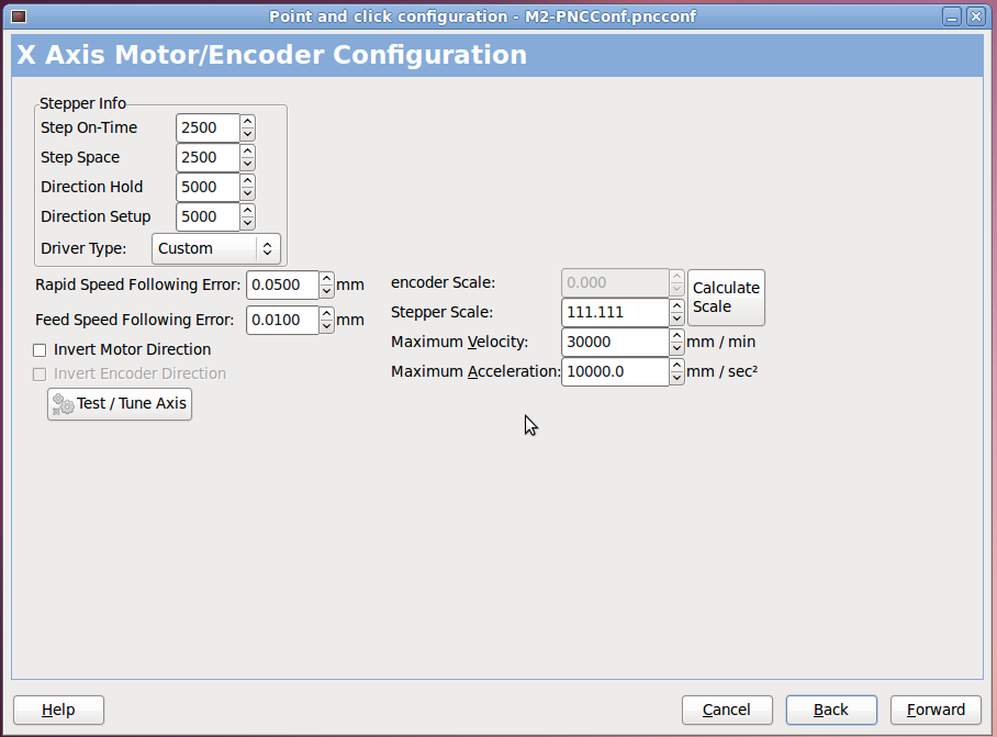
I used the LinuxCNC PNCConf utility to define a minimal system with little more than the X axis parameters filled in:
PNCConf – X Axis
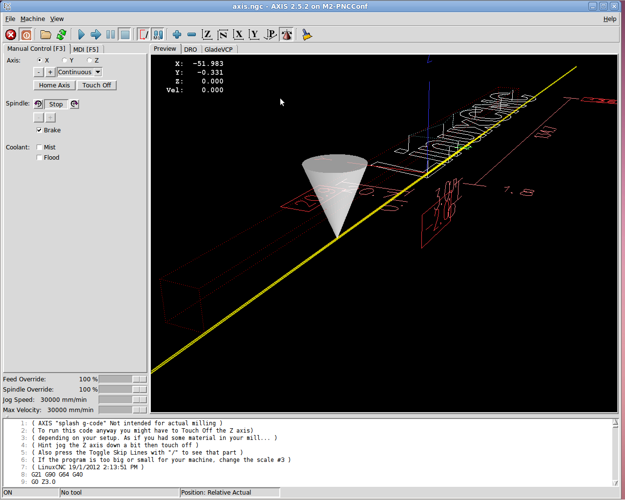
Then I could jog the stepper motor using the Axis UI:
7i76 – First Motion
And it worked!
Actually, it didn’t. The first motion instantly tripped a Following Error, so I bumped those values up a bit. Then I fiddled with accelerations and speeds and suchlike. Then I adjusted the Axis defaults to not be so nose-pickin’ slow. And then it Just Worked.
Not much to show, but at least I know the whole LinuxCNC to 5i25 to 7i76 to M542 to motor chain functions pretty much as it should, which is worth knowing. From here on out, it’s a matter of fine tuning…
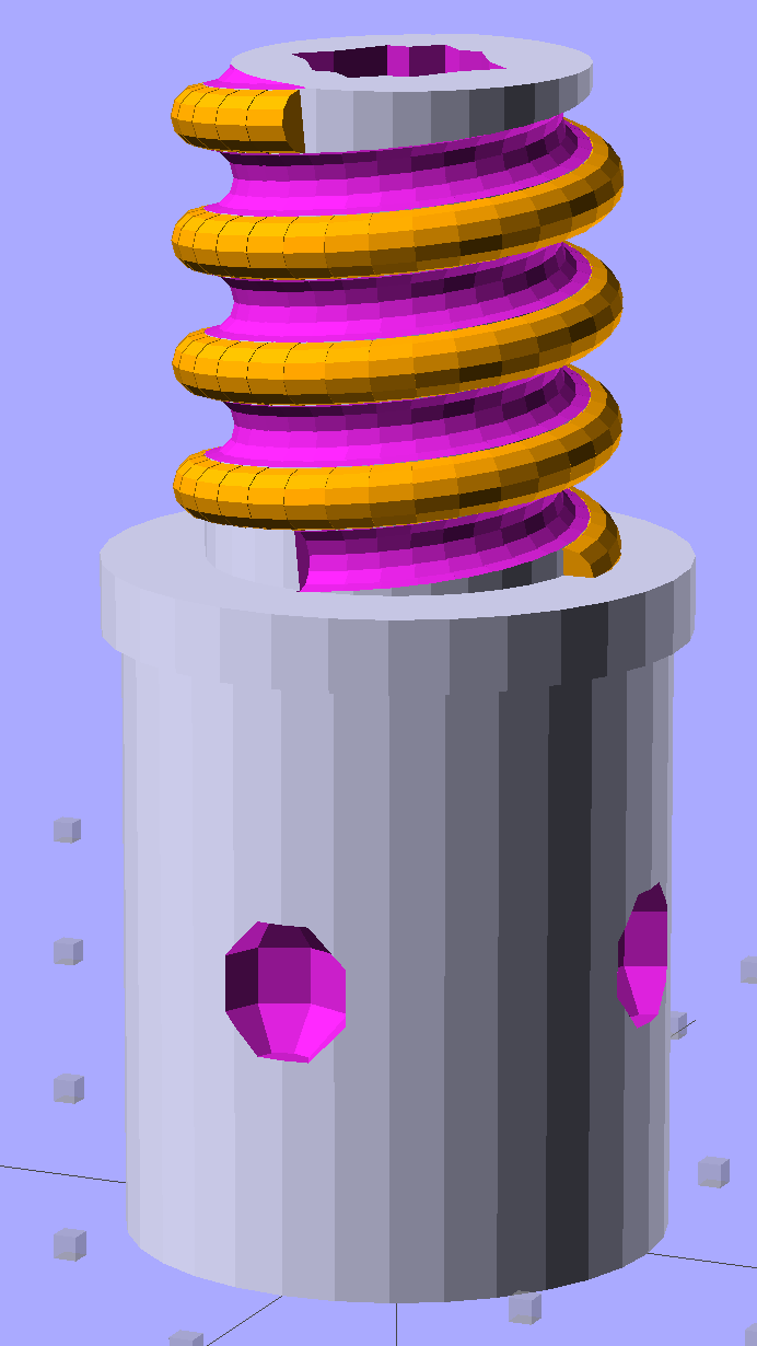
Although I don’t need another threaded plug, the most recent OpenSCAD version can handle a model including the thread dedendum:
Broom Handle Screw – full thread – solid model
This hyper-close view (as always, clicky for more dots) shows the problem: the region where the addendum and dedendum meet at the pitch cylinder consists of a bazillion tiny faces:
Broom Handle Screw – full thread – detail
The previous version simply couldn’t handle that many elements, but the new version has a parameter that I tweaked (to 100,000), allowing it to complete the rendering. Compiling to a solid model requires about 45 minutes, most of which probably involves those unprintably small facets.
The thread elements now taper slightly in the downhill direction, so that each quasi-cylinder nests cleanly inside the next to avoid the tiny slivers that stuck out of the joints in the previous model.
And the new Slic3r version (from GitHub) has better internal support for those indentations around the base, which means that AC vent plug might be build-able, too.
The OpenSCAD source code, with a few tweaks to nest the thread cylinders and properly locate the dedendum:
// Broom Handle Screw End Plug
// Ed Nisley KE4ZNU June 2013

//- Extrusion parameters must match reality!
//  Print with 2 shells and 3 solid layers

HoleWindage = 0.2;

Protrusion = 0.1;			// make holes end cleanly

//----------------------
// Dimensions

PostOD = 22.3;				// post inside metal handle
PostLength = 25.0;

FlangeOD = 24.0;			// stop flange
FlangeLength = 3.0;

PitchDia = 15.5;			// thread center diameter
ScrewLength = 20.0;

ThreadFormOD = 2.5;			// diameter of thread form
ThreadPitch = 5.0;

BoltOD = 7.0;				// clears 1/4-20 bolt
BoltSquare = 6.5;			// across flats
BoltHeadThick = 3.0;

RecessDia = 6.0;			// recesss to secure post in handle

OALength = PostLength + FlangeLength + ScrewLength;

$fn=8*4;					// default cylinder sides

echo("Pitch dia: ",PitchDia);
echo("Root dia: ",PitchDia - ThreadFormOD);
echo("Crest dia: ",PitchDia + ThreadFormOD);

Pi = 3.14159265358979;

//----------------------
// Useful routines

// Wrap cylindrical thread segments around larger plug cylinder

module CylinderThread(Pitch,Length,PitchDia,ThreadOD,PerTurn=32) {

CylFudge = 1.02;				// force overlap

    RotIncr = 1/PerTurn;
    PitchRad = PitchDia/2;

    Turns = Length/Pitch;
    NumCyls = Turns*PerTurn;

    ZStep = Pitch / PerTurn;

    HelixAngle = atan(Pitch/(Pi*PitchDia));
    CylLength = CylFudge * (Pi*(PitchDia + ThreadOD) / PerTurn) / cos(HelixAngle);

	for (i = [0:NumCyls-1]) {
		assign(Angle = 360*i/PerTurn)
			translate([PitchRad*cos(Angle),PitchRad*sin(Angle),i*ZStep])
				rotate([90+HelixAngle,0,Angle])
					cylinder(r1=ThreadOD/2,
							r2=ThreadOD/(2*CylFudge),
							h=CylLength,
							center=true,$fn=12);
	}
}

module PolyCyl(Dia,Height,ForceSides=0) {			// based on nophead's polyholes

  Sides = (ForceSides != 0) ? ForceSides : (ceil(Dia) + 2);

  FixDia = Dia / cos(180/Sides);

  cylinder(r=(FixDia + HoleWindage)/2,
           h=Height,
	   $fn=Sides);
}

module ShowPegGrid(Space = 10.0,Size = 1.0) {

  Range = floor(50 / Space);

	for (x=[-Range:Range])
	  for (y=[-Range:Range])
		translate([x*Space,y*Space,Size/2])
		  %cube(Size,center=true);

}

//-------------------
// Build it...

ShowPegGrid();

difference() {
    union() {
        cylinder(r=PostOD/2,h=PostLength);
        cylinder(r=PitchDia/2,h=OALength);
        translate([0,0,PostLength])
            cylinder(r=FlangeOD/2,h=FlangeLength);
        color("Orange")
        translate([0,0,(PostLength + FlangeLength)])
            CylinderThread(ThreadPitch,(ScrewLength - ThreadFormOD/2),PitchDia,ThreadFormOD);
    }

    translate([0,0,-Protrusion])
        PolyCyl(BoltOD,(OALength + 2*Protrusion),6);
    translate([0,0,(OALength - BoltHeadThick)])
        PolyCyl(BoltSquare,(BoltHeadThick + Protrusion),4);

    translate([0,0,(PostLength + FlangeLength + ThreadFormOD/2)])
		rotate(-90)
        CylinderThread(ThreadPitch,ScrewLength,PitchDia,ThreadFormOD);

	for (i = [0:90:270]) {
		rotate(i)
			translate([PostOD/2,0,PostLength/2])
				sphere(r=RecessDia/2,$fn=8);
	}
}
First up: note that Mesa uses a capital I (“eye”) in the part numbers, a decision which they’ve surely had plenty of time to regret, as many common fonts exhibit nearly identical capital-I and digit-1 characters.
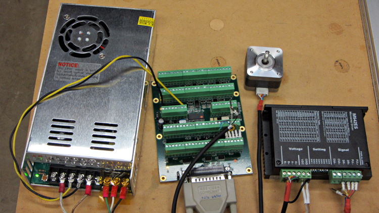
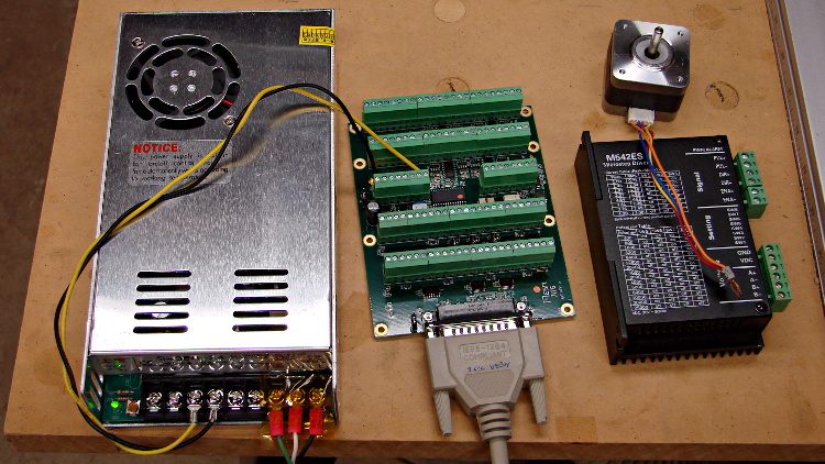
The 7i76 connects to the 5i25 in the PC through a Mesa-supplied IEEE-1284 printer cable. I cobbled up a 24 VDC power supply (which I’ll eventually be using for the M2 motors) to provide “field power” and let the firmware identify the daughtercard:
24 VDC power supply – Mesa 7i76 – stepper driver
The default jumper positions on both cards work fine.
The unconnected stepper driver brick and motor will serve as a simple demonstration after I’ve built the Eagle parts to represent the 5i25’s components. However, the first demo of any new hardware must be a blinking LED.
To see whether the cards work and are detected, load the hostmot2 drivers in halrun and dump all the information:
halrun
halcmd: loadrt hostmot2
halcmd: loadrt hm2_pci
halcmd: show all
Loaded HAL Components:
ID      Type  Name                                      PID   State
     5  RT    hm2_pci                                         ready
     3  User  halcmd5010                                 5010 ready
     4  RT    hostmot2                                        ready

Component Pins:
Owner   Type  Dir         Value  Name
     5  bit   OUT         FALSE  hm2_5i25.0.7i76.0.0.input-00
     5  bit   OUT         FALSE  hm2_5i25.0.7i76.0.0.input-00-not
     5  bit   OUT         FALSE  hm2_5i25.0.7i76.0.0.input-01
... snippage ...
     5  bit   OUT         FALSE  hm2_5i25.0.7i76.0.0.input-30
     5  bit   OUT         FALSE  hm2_5i25.0.7i76.0.0.input-30-not
     5  bit   OUT         FALSE  hm2_5i25.0.7i76.0.0.input-31
     5  bit   OUT         FALSE  hm2_5i25.0.7i76.0.0.input-31-not
     5  bit   IN          FALSE  hm2_5i25.0.7i76.0.0.output-00
     5  bit   IN          FALSE  hm2_5i25.0.7i76.0.0.output-01
... snippage ...
     5  bit   IN          FALSE  hm2_5i25.0.7i76.0.0.output-15
     5  bit   IN          FALSE  hm2_5i25.0.7i76.0.0.spindir
     5  bit   IN          FALSE  hm2_5i25.0.7i76.0.0.spinena
     5  float IN              0  hm2_5i25.0.7i76.0.0.spinout
     5  s32   OUT             0  hm2_5i25.0.encoder.00.count
     5  s32   OUT             0  hm2_5i25.0.encoder.00.count-latched
     5  bit   I/O         FALSE  hm2_5i25.0.encoder.00.index-enable
     5  bit   IN          FALSE  hm2_5i25.0.encoder.00.latch-enable
     5  bit   IN          FALSE  hm2_5i25.0.encoder.00.latch-polarity
     5  float OUT             0  hm2_5i25.0.encoder.00.position
     5  float OUT             0  hm2_5i25.0.encoder.00.position-latched
     5  s32   OUT             0  hm2_5i25.0.encoder.00.rawcounts
     5  s32   OUT             0  hm2_5i25.0.encoder.00.rawlatch
     5  bit   IN          FALSE  hm2_5i25.0.encoder.00.reset
     5  float OUT             0  hm2_5i25.0.encoder.00.velocity
     5  s32   OUT             0  hm2_5i25.0.encoder.01.count
... snippage ...
     5  float OUT             0  hm2_5i25.0.encoder.01.velocity
     5  bit   OUT         FALSE  hm2_5i25.0.gpio.000.in
     5  bit   OUT          TRUE  hm2_5i25.0.gpio.000.in_not
     5  bit   OUT         FALSE  hm2_5i25.0.gpio.001.in
... snippage ...
     5  bit   OUT          TRUE  hm2_5i25.0.gpio.032.in
     5  bit   OUT         FALSE  hm2_5i25.0.gpio.032.in_not
     5  bit   OUT          TRUE  hm2_5i25.0.gpio.033.in
     5  bit   OUT         FALSE  hm2_5i25.0.gpio.033.in_not
     5  bit   IN          FALSE  hm2_5i25.0.led.CR01
     5  bit   IN          FALSE  hm2_5i25.0.led.CR02
     5  u32   IN     0x00000000  hm2_5i25.0.sserial.channel
     5  u32   IN     0x00000000  hm2_5i25.0.sserial.parameter
     5  u32   IN     0x00000000  hm2_5i25.0.sserial.port
     5  u32   OUT    0x00000000  hm2_5i25.0.sserial.port-0.fault-count
     5  u32   OUT    0x00000000  hm2_5i25.0.sserial.port-0.port_state
     5  bit   IN           TRUE  hm2_5i25.0.sserial.port-0.run
     5  bit   IN          FALSE  hm2_5i25.0.sserial.read
     5  u32   OUT    0x00000000  hm2_5i25.0.sserial.state
     5  u32   IN     0x00000000  hm2_5i25.0.sserial.value
     5  bit   IN          FALSE  hm2_5i25.0.sserial.write
     5  bit   IN          FALSE  hm2_5i25.0.stepgen.00.control-type
     5  s32   OUT             0  hm2_5i25.0.stepgen.00.counts
     5  float OUT             0  hm2_5i25.0.stepgen.00.dbg_err_at_match
     5  float OUT             0  hm2_5i25.0.stepgen.00.dbg_ff_vel
     5  float OUT             0  hm2_5i25.0.stepgen.00.dbg_pos_minus_prev_
     5  float OUT             0  hm2_5i25.0.stepgen.00.dbg_s_to_match
     5  s32   OUT             0  hm2_5i25.0.stepgen.00.dbg_step_rate
     5  float OUT             0  hm2_5i25.0.stepgen.00.dbg_vel_error
     5  bit   IN          FALSE  hm2_5i25.0.stepgen.00.enable
     5  float IN              0  hm2_5i25.0.stepgen.00.position-cmd
     5  float OUT             0  hm2_5i25.0.stepgen.00.position-fb
     5  float IN              0  hm2_5i25.0.stepgen.00.velocity-cmd
     5  float OUT             0  hm2_5i25.0.stepgen.00.velocity-fb
     5  bit   IN          FALSE  hm2_5i25.0.stepgen.01.control-type
... snippage ...
     5  float OUT             0  hm2_5i25.0.stepgen.09.velocity-fb
     5  bit   I/O         FALSE  hm2_5i25.0.watchdog.has_bit

... snippage ...

Parameters:
Owner   Type  Dir         Value  Name
     5  bit   RW          FALSE  hm2_5i25.0.7i76.0.0.output-00-invert
     5  bit   RW          FALSE  hm2_5i25.0.7i76.0.0.output-01-invert
... snippage ...
     5  bit   RW          FALSE  hm2_5i25.0.7i76.0.0.output-15-invert
     5  u32   RO     0x100000A5  hm2_5i25.0.7i76.0.0.serial-number
     5  bit   RW          FALSE  hm2_5i25.0.7i76.0.0.spindir-invert
     5  bit   RW          FALSE  hm2_5i25.0.7i76.0.0.spinena-invert
     5  float RW            100  hm2_5i25.0.7i76.0.0.spinout-maxlim
     5  float RW              0  hm2_5i25.0.7i76.0.0.spinout-minlim
     5  float RW            100  hm2_5i25.0.7i76.0.0.spinout-scalemax
     5  u32   RO     0x00000000  hm2_5i25.0.7i76.0.0.status
     5  bit   RW          FALSE  hm2_5i25.0.encoder.00.counter-mode
     5  bit   RW           TRUE  hm2_5i25.0.encoder.00.filter
     5  bit   RW          FALSE  hm2_5i25.0.encoder.00.index-invert
     5  bit   RW          FALSE  hm2_5i25.0.encoder.00.index-mask
     5  bit   RW          FALSE  hm2_5i25.0.encoder.00.index-mask-invert
     5  float RW              1  hm2_5i25.0.encoder.00.scale
     5  float RW            0.5  hm2_5i25.0.encoder.00.vel-timeout
     5  bit   RW          FALSE  hm2_5i25.0.encoder.01.counter-mode
... snippage ...
     5  float RW            0.5  hm2_5i25.0.encoder.01.vel-timeout
     5  bit   RW          FALSE  hm2_5i25.0.gpio.000.invert_output
     5  bit   RW          FALSE  hm2_5i25.0.gpio.000.is_opendrain
     5  bit   RW          FALSE  hm2_5i25.0.gpio.001.invert_output
... snippage ...
     5  bit   RW          FALSE  hm2_5i25.0.gpio.030.invert_output
     5  bit   RW          FALSE  hm2_5i25.0.gpio.030.is_opendrain
     5  bit   RW          FALSE  hm2_5i25.0.gpio.030.is_output
     5  bit   RW          FALSE  hm2_5i25.0.io_error
     5  s32   RO              0  hm2_5i25.0.pet_watchdog.time
     5  s32   RW              0  hm2_5i25.0.pet_watchdog.tmax
     5  s32   RO              0  hm2_5i25.0.read.time
     5  s32   RW              0  hm2_5i25.0.read.tmax
     5  s32   RO              0  hm2_5i25.0.read_gpio.time
     5  s32   RW              0  hm2_5i25.0.read_gpio.tmax
     5  u32   RW     0x00000001  hm2_5i25.0.sserial.port-0.fault-dec
     5  u32   RW     0x0000000A  hm2_5i25.0.sserial.port-0.fault-inc
     5  u32   RW     0x000000C8  hm2_5i25.0.sserial.port-0.fault-lim
     5  u32   RW     0x00077FE2  hm2_5i25.0.stepgen.00.dirhold
     5  u32   RW     0x00077FE2  hm2_5i25.0.stepgen.00.dirsetup
     5  float RW              1  hm2_5i25.0.stepgen.00.maxaccel
     5  float RW              0  hm2_5i25.0.stepgen.00.maxvel
     5  float RW              1  hm2_5i25.0.stepgen.00.position-scale
     5  u32   RW     0x00000000  hm2_5i25.0.stepgen.00.step_type
     5  u32   RW     0x00077FE2  hm2_5i25.0.stepgen.00.steplen
     5  u32   RW     0x00077FE2  hm2_5i25.0.stepgen.00.stepspace
     5  u32   RW     0x00077FE2  hm2_5i25.0.stepgen.01.dirhold
... snippage ...
     5  u32   RW     0x00077FE2  hm2_5i25.0.stepgen.09.stepspace
     5  u32   RW     0x004C4B40  hm2_5i25.0.watchdog.timeout_ns
     5  s32   RO              0  hm2_5i25.0.write.time
     5  s32   RW              0  hm2_5i25.0.write.tmax
     5  s32   RO              0  hm2_5i25.0.write_gpio.time
     5  s32   RW              0  hm2_5i25.0.write_gpio.tmax

Parameter Aliases:
 Alias                                      Original Name

Exported Functions:
Owner   CodeAddr  Arg       FP   Users  Name
 00005  fc3d2582  f1b17000  NO       0   hm2_5i25.0.pet_watchdog
 00005  fc3c49dc  f1b17000  YES      0   hm2_5i25.0.read
 00005  fc3c4906  f1b17000  YES      0   hm2_5i25.0.read_gpio
 00005  fc3c4936  f1b17000  YES      0   hm2_5i25.0.write
 00005  fc3c48d6  f1b17000  YES      0   hm2_5i25.0.write_gpio

... snippage ...
Extract the 5i25 pin assignments from the kernel log file: dmesg | grep hm2
I am, perhaps, easily confused, but it took me a while to realize those pin assignments apply to the 5i25 back panel and on-card connectors, not the 7i76 daughter card’s screw terminals. Yeah, it says 5i25 right there in the dump, but …
The Fine 7i76 Manual gives the 7i76 pin connections, so they’re not even slightly hidden. [sigh]
I planned to use an old Dell Inspiron 531S AMD desktop for the LinuxCNC installation, but it turned out to have terrible interrupt latency, despite fiddling with all the available BIOS settings and video drivers. Mostly, it ran fine, but would occasionally burp up a millisecond-long latency spike for no apparent reason. So it’s now on the harvest / recycle heap.
A new-to-me off-lease Dell Optiplex 760 Core 2 Duo in the SDT (Small Desktop Tower) configuration has similar latency numbers:
Optiplex 760 latency – isolcpu 1
What’s important here is that the latency remains rock-solid stable at those numbers. Contrary to my experience with the D520 and D525 Atoms, isolating one CPU for the real-time tasks didn’t make any noticeable difference, but it’s running that way because the overall performance isn’t a problem.
Latency around 20 μs is near the upper limit for successful software step generation at any reasonable pace; the LinuxCNC description has more details. In round numbers, running the M2 at 500 mm/s needs a 40 kHz step rate in 1/16 microstep mode = a 25 μs period, which means 20 μs of jitter wouldn’t work well at all. Which is why I’m using Mesa FPGA card to get hardware step generation: it makes such problems Go Away.
The Optiplex arrived with Windows Vista Business preinstalled; it dates back to mid-2009. I used System Rescue CD to shrink the Windows partition, added a few more, then installed LinuxCNC direct from the CD image (based on Ubuntu 10.04 LTS) and Xubuntu 13.04. The latter serves as a general-purpose installation for times when I don’t need LinuxCNC, because 10.04 is pretty much obsolete for anything other than real-time control.
Digression 1: Yes, 10.04 LTS. TheRTAI project hasn’t released the patches that will slip the real-time kernel under the stock 3.x Linux kernel: LinuxCNC remains stuck at 10.04 LTS. Those changes have been coming Real Soon Now for quite a while; as with most Open Source projects, they could use more manpower and money. This isn’t a problem, as LinuxCNC is used for motion control, not a general-purpose operating system.
The SDT case has room for two PCI cards and one PCI-E video card, so I installed the dual-head video card that couldn’t handle the U2711 monitor’s dual-DVI connection (although I’m using only DVI Output 1) and a Mesa 5i25. The middle “card” is actually a tiny PCB connected to a ribbon cable that brings out a second serial port (remember serial ports?) and what could be either or both of a PS2 keyboard or mouse connection (remember PS/2?).
Optiplex 760 SDT – dual DVI – serial – 5i25
The back panel has a parallel printer port (which may come in handy for something) and a serial port, although you’re expected to have USB mice and keyboards these days. The front panel even has a floppy drive…
Digression 2: LinuxCNC does not require a parallel printer port; this seems to be a common misconception among folks who don’t actually know how it works. The Mesa 5i25 FPGA card with a 7i76 step-direction daughter board provides high-resolution timing for five axes, rotary encoder inputs, a bunch of buffered digital I/O bits, a watchdog timer, plus various other useful odds and ends, all behind handy screw terminals.
The Optiplex 760 has on-board VGA-class video that would also work fine, but the monitor I’m using has its VGA input connected to the box driving the Sherline mill and an unused DVI input. Having that dual-DVI monitor card lying around, I figured I could attach the same monitor to both systems and just poke the monitor’s input section button; I’ve found KVM switches unreliable in this application.
The usual setup preps the system for public-key SSH on a nonstandard port, sets up the NFS mounts, and tweaks this-and-that: it’s running just fine.
Digression 3: SSH kvetches when you swap server boxes at the same IP address, as well it should. If you’re foolish enough to have two separate Linux installs on the same box with the same IP, SSH reminds you every time you boot the other distro…
Mary’s folks enjoy the daily crossword, but they wanted a slightly larger edition… and, after a bit of procrastination, I conjured up an automated way to make it happen, so her father need not do this manually with The GIMP and Xsane.
The scanner, an old HP Scanjet 3970, dropped off the Windows driver list after Vista, so it now runs only with Linux.
Doing the scan is straightforward, as it’s the default scanner:
The X and Y coordinates set the scan dimensions in millimeters, which should be as small as possible consistent with scanning the whole crossword.
The driver produces output image files in PNM format, which isn’t particularly common these days, or TIFF. ImageMagick knows what to do with both of them; I picked PNM.
Unfortunately, for some unknown reason, the SANE driver produces a severely low-contrast image:
HP3900 Grayscale Scan
ImageMagick can produce a histogram:
convert scan.pnm histogram:hist.png
Which shows the problem:
HP3900 Grayscale Histogram
That’s using the grayscale emulation mode: the driver does a Color scan and converts to Gray mode for the output image. It seems having the driver do the conversion produces better results than scanning directly in Color and then applying ImageMagick, but it’s not my scanner and I don’t have a lot of experience with it.
This being Linux, the best way to print something is with either Postscript or PDF. I used PDF, because then we can look at the results with Reader, a more familiar program than, say, Evince:
Which centers the crossword on the page over a white background with enough margin to keep the printer happy:
Crossword – full page
That PDF goes to the default printer queue, where it’s turned into Postscript and comes out exactly like it should:
lp page.pdf
I gimmicked the default printer instance to use only black ink by creating a separate CUPS printer with the appropriate defaults. Other programs pay no attention to that setting and the printer uses colored inks. There is no explanation I can find for any of this; Linux / CUPS printing is basically a black box operation.
In theory, you could print the composited image file as a PNG or some such, but I cannot make it come out the right size in the right place.
You could do all of that in one line, with one huge ImageMagick invocation kicking off the scan and firing the result to the printer, but leaving some intermediate results lying along the trail isn’t necessarily a Bad Thing. I should probably use random temporary file names, though, in the interest of not polluting the namespace.
All this happened remotely, with me signed on through SSH: hooray for the command line. Had to use SCP a few times to fetch those intermediate files to puzzle over the results, too.
Dan Newman’s TC4Server turns the TC4 thermocouple board into a USB HID input device that’s compatible with HAL’s hal_input module:
TC4 on ProtoScrewShield on Leonardo
For simplicity (i.e., to avoid writing a special driver), TC4Server misrepresents itself as a nine-axis joystick-like device suited for RC airplane control:
halrun
halcmd: loadusr -W hal_input +A Leonardo
halcmd: show
... snippage ...
Component Pins:
Owner   Type  Dir         Value  Name
     5  s32   OUT          2941  input.0.abs-rudder-counts
     5  s32   IN           4095  input.0.abs-rudder-flat
     5  s32   IN            255  input.0.abs-rudder-fuzz
     5  bit   OUT          TRUE  input.0.abs-rudder-is-neg
     5  bit   OUT         FALSE  input.0.abs-rudder-is-pos
     5  float IN        32767.5  input.0.abs-rudder-offset
     5  float OUT    -0.9102464  input.0.abs-rudder-position
     5  float IN        32767.5  input.0.abs-rudder-scale
     5  s32   OUT          2947  input.0.abs-rx-counts
     5  s32   IN           4095  input.0.abs-rx-flat
     5  s32   IN            255  input.0.abs-rx-fuzz
     5  bit   OUT          TRUE  input.0.abs-rx-is-neg
     5  bit   OUT         FALSE  input.0.abs-rx-is-pos
     5  float IN        32767.5  input.0.abs-rx-offset
     5  float OUT    -0.9100633  input.0.abs-rx-position
     5  float IN        32767.5  input.0.abs-rx-scale
     5  s32   OUT         65535  input.0.abs-ry-counts
     5  s32   IN           4095  input.0.abs-ry-flat
     5  s32   IN            255  input.0.abs-ry-fuzz
     5  bit   OUT         FALSE  input.0.abs-ry-is-neg
     5  bit   OUT          TRUE  input.0.abs-ry-is-pos
     5  float IN        32767.5  input.0.abs-ry-offset
     5  float OUT             1  input.0.abs-ry-position
     5  float IN        32767.5  input.0.abs-ry-scale
     5  s32   OUT         65535  input.0.abs-rz-counts
     5  s32   IN           4095  input.0.abs-rz-flat
     5  s32   IN            255  input.0.abs-rz-fuzz
     5  bit   OUT         FALSE  input.0.abs-rz-is-neg
     5  bit   OUT          TRUE  input.0.abs-rz-is-pos
     5  float IN        32767.5  input.0.abs-rz-offset
     5  float OUT             1  input.0.abs-rz-position
     5  float IN        32767.5  input.0.abs-rz-scale
     5  s32   OUT         65535  input.0.abs-throttle-counts
     5  s32   IN           4095  input.0.abs-throttle-flat
     5  s32   IN            255  input.0.abs-throttle-fuzz
     5  bit   OUT         FALSE  input.0.abs-throttle-is-neg
     5  bit   OUT          TRUE  input.0.abs-throttle-is-pos
     5  float IN        32767.5  input.0.abs-throttle-offset
     5  float OUT             1  input.0.abs-throttle-position
     5  float IN        32767.5  input.0.abs-throttle-scale
     5  s32   OUT          2957  input.0.abs-wheel-counts
     5  s32   IN           4095  input.0.abs-wheel-flat
     5  s32   IN            255  input.0.abs-wheel-fuzz
     5  bit   OUT          TRUE  input.0.abs-wheel-is-neg
     5  bit   OUT         FALSE  input.0.abs-wheel-is-pos
     5  float IN        32767.5  input.0.abs-wheel-offset
     5  float OUT    -0.9097581  input.0.abs-wheel-position
     5  float IN        32767.5  input.0.abs-wheel-scale
     5  s32   OUT          2942  input.0.abs-x-counts
     5  s32   IN           4095  input.0.abs-x-flat
     5  s32   IN            255  input.0.abs-x-fuzz
     5  bit   OUT          TRUE  input.0.abs-x-is-neg
     5  bit   OUT         FALSE  input.0.abs-x-is-pos
     5  float IN        32767.5  input.0.abs-x-offset
     5  float OUT    -0.9102159  input.0.abs-x-position
     5  float IN        32767.5  input.0.abs-x-scale
     5  s32   OUT          2942  input.0.abs-y-counts
     5  s32   IN           4095  input.0.abs-y-flat
     5  s32   IN            255  input.0.abs-y-fuzz
     5  bit   OUT          TRUE  input.0.abs-y-is-neg
     5  bit   OUT         FALSE  input.0.abs-y-is-pos
     5  float IN        32767.5  input.0.abs-y-offset
     5  float OUT    -0.9102159  input.0.abs-y-position
     5  float IN        32767.5  input.0.abs-y-scale
     5  s32   OUT          2940  input.0.abs-z-counts
     5  s32   IN           4095  input.0.abs-z-flat
     5  s32   IN            255  input.0.abs-z-fuzz
     5  bit   OUT          TRUE  input.0.abs-z-is-neg
     5  bit   OUT         FALSE  input.0.abs-z-is-pos
     5  float IN        32767.5  input.0.abs-z-offset
     5  float OUT     -0.910277  input.0.abs-z-position
     5  float IN        32767.5  input.0.abs-z-scale
     5  s32   OUT          2941  input.1.abs-rudder-counts
     5  s32   IN           4095  input.1.abs-rudder-flat
     5  s32   IN            255  input.1.abs-rudder-fuzz
     5  bit   OUT          TRUE  input.1.abs-rudder-is-neg
     5  bit   OUT         FALSE  input.1.abs-rudder-is-pos
     5  float IN        32767.5  input.1.abs-rudder-offset
     5  float OUT    -0.9102464  input.1.abs-rudder-position
     5  float IN        32767.5  input.1.abs-rudder-scale
     5  s32   OUT          2947  input.1.abs-rx-counts
     5  s32   IN           4095  input.1.abs-rx-flat
     5  s32   IN            255  input.1.abs-rx-fuzz
     5  bit   OUT          TRUE  input.1.abs-rx-is-neg
     5  bit   OUT         FALSE  input.1.abs-rx-is-pos
     5  float IN        32767.5  input.1.abs-rx-offset
     5  float OUT    -0.9100633  input.1.abs-rx-position
     5  float IN        32767.5  input.1.abs-rx-scale
     5  s32   OUT         65535  input.1.abs-ry-counts
     5  s32   IN           4095  input.1.abs-ry-flat
     5  s32   IN            255  input.1.abs-ry-fuzz
     5  bit   OUT         FALSE  input.1.abs-ry-is-neg
     5  bit   OUT          TRUE  input.1.abs-ry-is-pos
     5  float IN        32767.5  input.1.abs-ry-offset
     5  float OUT             1  input.1.abs-ry-position
     5  float IN        32767.5  input.1.abs-ry-scale
     5  s32   OUT         65535  input.1.abs-rz-counts
     5  s32   IN           4095  input.1.abs-rz-flat
     5  s32   IN            255  input.1.abs-rz-fuzz
     5  bit   OUT         FALSE  input.1.abs-rz-is-neg
     5  bit   OUT          TRUE  input.1.abs-rz-is-pos
     5  float IN        32767.5  input.1.abs-rz-offset
     5  float OUT             1  input.1.abs-rz-position
     5  float IN        32767.5  input.1.abs-rz-scale
     5  s32   OUT         65535  input.1.abs-throttle-counts
     5  s32   IN           4095  input.1.abs-throttle-flat
     5  s32   IN            255  input.1.abs-throttle-fuzz
     5  bit   OUT         FALSE  input.1.abs-throttle-is-neg
     5  bit   OUT          TRUE  input.1.abs-throttle-is-pos
     5  float IN        32767.5  input.1.abs-throttle-offset
     5  float OUT             1  input.1.abs-throttle-position
     5  float IN        32767.5  input.1.abs-throttle-scale
     5  s32   OUT          2957  input.1.abs-wheel-counts
     5  s32   IN           4095  input.1.abs-wheel-flat
     5  s32   IN            255  input.1.abs-wheel-fuzz
     5  bit   OUT          TRUE  input.1.abs-wheel-is-neg
     5  bit   OUT         FALSE  input.1.abs-wheel-is-pos
     5  float IN        32767.5  input.1.abs-wheel-offset
     5  float OUT    -0.9097581  input.1.abs-wheel-position
     5  float IN        32767.5  input.1.abs-wheel-scale
     5  s32   OUT          2942  input.1.abs-x-counts
     5  s32   IN           4095  input.1.abs-x-flat
     5  s32   IN            255  input.1.abs-x-fuzz
     5  bit   OUT          TRUE  input.1.abs-x-is-neg
     5  bit   OUT         FALSE  input.1.abs-x-is-pos
     5  float IN        32767.5  input.1.abs-x-offset
     5  float OUT    -0.9102159  input.1.abs-x-position
     5  float IN        32767.5  input.1.abs-x-scale
     5  s32   OUT          2942  input.1.abs-y-counts
     5  s32   IN           4095  input.1.abs-y-flat
     5  s32   IN            255  input.1.abs-y-fuzz
     5  bit   OUT          TRUE  input.1.abs-y-is-neg
     5  bit   OUT         FALSE  input.1.abs-y-is-pos
     5  float IN        32767.5  input.1.abs-y-offset
     5  float OUT    -0.9102159  input.1.abs-y-position
     5  float IN        32767.5  input.1.abs-y-scale
     5  s32   OUT          2940  input.1.abs-z-counts
     5  s32   IN           4095  input.1.abs-z-flat
     5  s32   IN            255  input.1.abs-z-fuzz
     5  bit   OUT          TRUE  input.1.abs-z-is-neg
     5  bit   OUT         FALSE  input.1.abs-z-is-pos
     5  float IN        32767.5  input.1.abs-z-offset
     5  float OUT     -0.910277  input.1.abs-z-position
     5  float IN        32767.5  input.1.abs-z-scale

... snippage ...
Parameters:
Owner   Type  Dir         Value  Name
     5  s32   RO          65535  input.0.abs-rudder-max
     5  s32   RO              0  input.0.abs-rudder-min
     5  s32   RO          65535  input.0.abs-rx-max
     5  s32   RO              0  input.0.abs-rx-min
     5  s32   RO          65535  input.0.abs-ry-max
     5  s32   RO              0  input.0.abs-ry-min
     5  s32   RO          65535  input.0.abs-rz-max
     5  s32   RO              0  input.0.abs-rz-min
     5  s32   RO          65535  input.0.abs-throttle-max
     5  s32   RO              0  input.0.abs-throttle-min
     5  s32   RO          65535  input.0.abs-wheel-max
     5  s32   RO              0  input.0.abs-wheel-min
     5  s32   RO          65535  input.0.abs-x-max
     5  s32   RO              0  input.0.abs-x-min
     5  s32   RO          65535  input.0.abs-y-max
     5  s32   RO              0  input.0.abs-y-min
     5  s32   RO          65535  input.0.abs-z-max
     5  s32   RO              0  input.0.abs-z-min
     5  s32   RO          65535  input.1.abs-rudder-max
     5  s32   RO              0  input.1.abs-rudder-min
     5  s32   RO          65535  input.1.abs-rx-max
     5  s32   RO              0  input.1.abs-rx-min
     5  s32   RO          65535  input.1.abs-ry-max
     5  s32   RO              0  input.1.abs-ry-min
     5  s32   RO          65535  input.1.abs-rz-max
     5  s32   RO              0  input.1.abs-rz-min
     5  s32   RO          65535  input.1.abs-throttle-max
     5  s32   RO              0  input.1.abs-throttle-min
     5  s32   RO          65535  input.1.abs-wheel-max
     5  s32   RO              0  input.1.abs-wheel-min
     5  s32   RO          65535  input.1.abs-x-max
     5  s32   RO              0  input.1.abs-x-min
     5  s32   RO          65535  input.1.abs-y-max
     5  s32   RO              0  input.1.abs-y-min
     5  s32   RO          65535  input.1.abs-z-max
     5  s32   RO              0  input.1.abs-z-min
... snippage ...
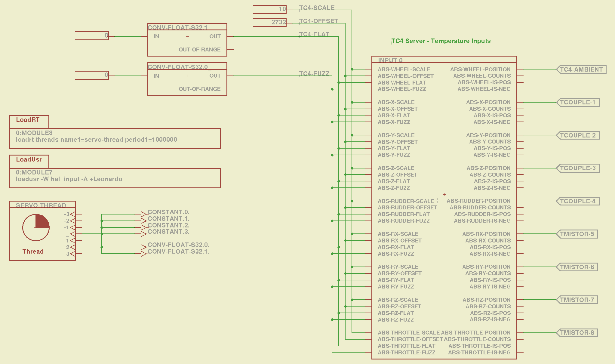
Dan’s program assigns the outputs thusly:
Wheel – ambient temperature as measured on TC4 board
X Y Z Rudder – thermocouples – channels 1 through 4
RX RY RZ Throttle – thermistors – channels 5 through 8
I created a huge Eagle device that encapsulates the whole thing. A simple demo schematic includes the constants that make the temperatures come out in °C:
TC4Server – Eagle Schematic
That picture produces this HAL file:
# HAL config file automatically generated by Eagle-CAD ULP:
# [/mnt/bulkdata/Project Files/eagle/ulp/hal-write-2.5.ulp]
# (C) Martin Schoeneck.de 2008
# Charalampos Alexopoulos 2011
# Mods Ed Nisley KE4ZNU 2010 2013
# Path        [/mnt/bulkdata/Project Files/eagle/projects/LinuxCNC for M2/]
# ProjectName [LinuxCNC M2 - TC4Server Test]
# File name   [/mnt/bulkdata/Project Files/eagle/projects/LinuxCNC for M2/TC4Server.hal]
# Created     [20:03:16 03-Jun-2013]

####################################################
# Load realtime and userspace modules
loadusr -W hal_input -A +Leonardo
loadrt threads name1=servo-thread period1=1000000
loadrt constant        count=4
loadrt conv_float_s32        count=2

####################################################
# Hook functions into threads
addf constant.0        servo-thread
addf constant.1        servo-thread
addf constant.2        servo-thread
addf constant.3        servo-thread
addf conv-float-s32.0        servo-thread
addf conv-float-s32.1        servo-thread

####################################################
# Set parameters

####################################################
# Set constants
setp constant.0.value    10
setp constant.1.value    2732
setp constant.2.value    0
setp constant.3.value    0

####################################################
# Connect Modules with nets
net n_2 constant.2.out conv-float-s32.1.in
net n_3 constant.3.out conv-float-s32.0.in
net tc4-ambient input.0.abs-wheel-position
net tc4-flat input.0.abs-wheel-flat input.0.abs-x-flat input.0.abs-y-flat input.0.abs-z-flat input.0.abs-rudder-flat input.0.abs-rx-flat input.0.abs-ry-flat input.0.abs-rz-flat input.0.abs-throttle-flat conv-float-s32.1.out
net tc4-fuzz input.0.abs-throttle-fuzz input.0.abs-rz-fuzz input.0.abs-ry-fuzz input.0.abs-rx-fuzz input.0.abs-rudder-fuzz input.0.abs-z-fuzz input.0.abs-y-fuzz input.0.abs-x-fuzz input.0.abs-wheel-fuzz conv-float-s32.0.out
net tc4-offset input.0.abs-wheel-offset input.0.abs-x-offset input.0.abs-y-offset input.0.abs-z-offset input.0.abs-rudder-offset input.0.abs-rx-offset input.0.abs-ry-offset input.0.abs-rz-offset input.0.abs-throttle-offset constant.1.out
net tc4-scale input.0.abs-wheel-scale input.0.abs-x-scale input.0.abs-y-scale input.0.abs-z-scale input.0.abs-rudder-scale input.0.abs-rx-scale input.0.abs-ry-scale input.0.abs-rz-scale input.0.abs-throttle-scale constant.0.out
net tcouple-1 input.0.abs-x-position
net tcouple-2 input.0.abs-y-position
net tcouple-3 input.0.abs-z-position
net tcouple-4 input.0.abs-rudder-position
net tmistor-5 input.0.abs-rx-position
net tmistor-6 input.0.abs-ry-position
net tmistor-7 input.0.abs-rz-position
net tmistor-8 input.0.abs-throttle-position
Fire it up with halrun to see the temperatures (alphabetically by the pin name):
halrun -I -f TC4Server.hal
halcmd: start
halcmd: show pin *position
Component Pins:
Owner   Type  Dir         Value  Name
     5  float OUT          20.9  input.0.abs-rudder-position ==> tcouple-4
     5  float OUT          21.5  input.0.abs-rx-position ==> tmistor-5
     5  float OUT        6280.3  input.0.abs-ry-position ==> tmistor-6
     5  float OUT        6280.3  input.0.abs-rz-position ==> tmistor-7
     5  float OUT        6280.3  input.0.abs-throttle-position ==> tmistor-8
     5  float OUT          22.5  input.0.abs-wheel-position ==> tc4-ambient
     5  float OUT            21  input.0.abs-x-position ==> tcouple-1
     5  float OUT            21  input.0.abs-y-position ==> tcouple-2
     5  float OUT          20.8  input.0.abs-z-position ==> tcouple-3
The sensors do not correspond to the picture at the top: only the first thermocouple and first thermistor are connected ; the ADC returns bogus data for disconnected inputs, which means you must be careful about tightening the wires and checking the result. Dan’s firmware has the ability to disable unused sensors, in which case you get a huge value; when used for heater control, a sensor failing high means the heater will turn off, but, should you use this gadget in a freezer, you might want them to fail low (so modify the code for your own use).
The ambient temperature reported for the board runs 1 or 2 °C higher than the actual ambient air temperature, probably because of all those components doing useful things up close to the sensor chip. That particular ambient temperature serves as the cold junction reference for the thermocouples; the other temperatures don’t change very much as the board warms up, so it’s all good.
Remember to issue the start command in halrun, because otherwise nothing changes.
Also remember that you must configure TC4Server with the thermistor characteristics before you use it as a hal_input device.