Ed Nisley's Blog: Shop notes, electronics, firmware, machinery, 3D printing, laser cuttery, and curiosities. Contents: 100% human thinking, 0% AI slop.
Category: Software
General-purpose computers doing something specific
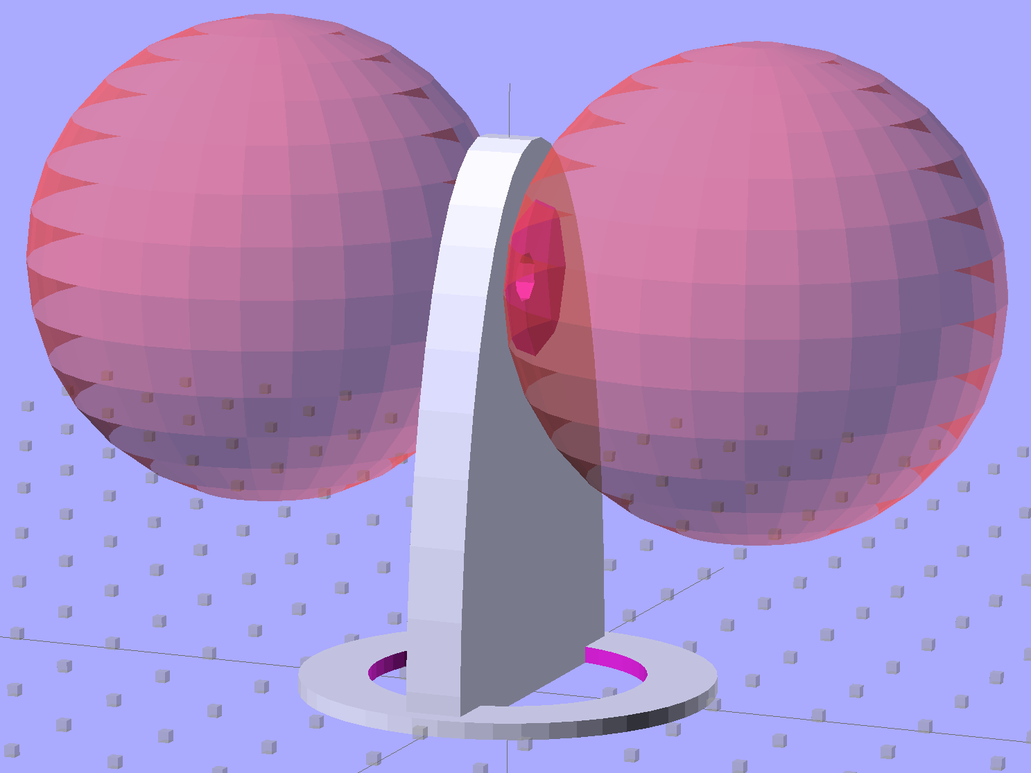
Then generate the sphere (well, two spheres, one for each dent) and offset it to scoop out the dent:
for (i=[-1,1]) {
translate([i*(DentSphereRadius + HandleThick/2 - DentDepth),0,StringHeight])
sphere(r=DentSphereRadius);
HandleThick controls exactly what you’d expect. StringHeight sets the location of the hole punched through the handle for a string, which is also the center of the dents.
The spheres have many facets, but only a few show up in the dent. I like the way the model looks, even if the facets don’t come through clearly in the plastic:
Quilting circle template – handle dent closeup – solid model
It Just Works and the exact math produces a better result than by-guess-and-by-gosh positioning.
The sphere radius will come out crazy large for very shallow dents. Here’s the helmet plate for my Bicycle Helmet Mirror Mount, which has an indentation (roughly) matching the curve on the side of my bike helmet:
Helmet mirror mount – plate
Here’s the sphere that makes the dent, at a somewhat different zoom scale:
Helmet mirror mount – plate with sphere
Don’t worry: trust the math, because It Just Works.
You find equations like that in Thomas Glover’s invaluable Pocket Ref. If you don’t have a copy, fix that problem right now; I don’t get a cut from the purchase, but you’ll decide you owe me anyway. Small, unmarked bills. Lots and lots of small unmarked bills…
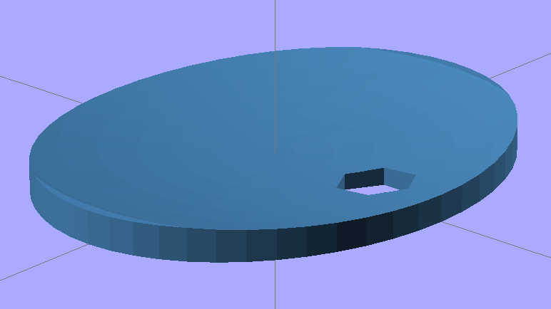
Mary just started an ambitious pieced quilt that requires 50-some-odd precisely sized 1-1/2 inch circles, with marks to locate a 1 inch circle in the middle. She started using a drafting template to mark the smaller circle on freezer paper (don’t ask, it’s complicated), but we couldn’t find the template I know I have with the larger circles.
So I says to my wife, I sez, “Hey, we have the technology. What would really simplify what you’re doing?” After a bit of doodling, we came up with a ring having the proper ID and OD, plus a flat handle of some sort.
Half an hour later, I had a solid model:
Quilting circle template – solid model
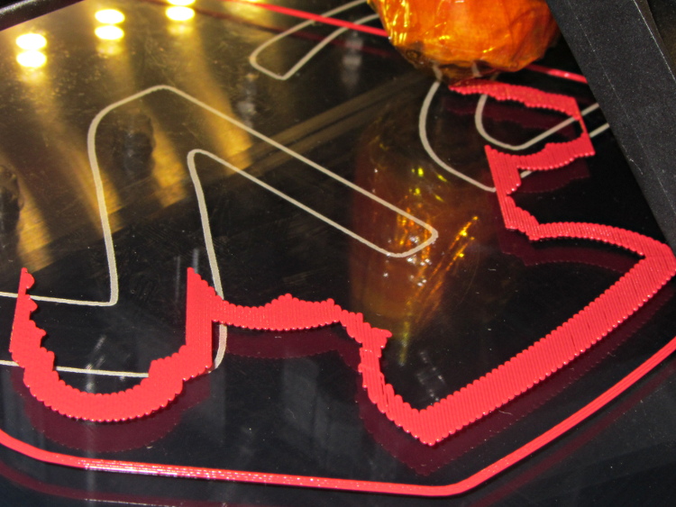
An hour after that I handed her a warm piece of plastic:
Quilting circle template
The bottom ring is exactly 1-1/2 inch OD, 1 inch ID, and thin enough to draw around. The handle keeps her fingers out of the way and even has grips and a hole for a string.
The print quality near the hole isn’t as good as I’d like, because the slicer turned that entire volume into a solid slab of plastic. I can fix that in the second version, but right now she has something to work with, evaluate, and figure out what would improve it.
3D printing isn’t for everybody, but it’s a vital part of my shop!
The OpenSCAD source code has parameters for everything, so we can crank out more templates without fuss:
// Quilting - Circle Template
// Ed Nisley KE4ZNU - July 2013
Layout = "Show"; // Show Build Circle Handle
//-------
//- Extrusion parameters must match reality!
// Print with 2 shells
ThreadThick = 0.25;
ThreadWidth = 0.40;
HoleFinagle = 0.2;
HoleFudge = 1.00;
function HoleAdjust(Diameter) = HoleFudge*Diameter + HoleFinagle;
Protrusion = 0.1; // make holes end cleanly
function IntegerMultiple(Size,Unit) = Unit * ceil(Size / Unit);
function IntegerMultipleMin(Size,Unit) = Unit * floor(Size / Unit);
inch = 25.4;
//-------
// Dimensions
CircleID = (1) * inch;
SeamAllowance = (1/4) * inch;
CircleOD = CircleID + 2*SeamAllowance;
CircleThick = 6*ThreadThick;
CircleSides = 12*4;
HandleHeight = (2) * inch;
HandleThick = IntegerMultiple(5.0,ThreadWidth);
HandleSides = 12*4;
StringDia = 4.0;
StringSides = 8;
StringHeight = 0.75*HandleHeight;
DentDepth = HandleThick/4;
DentDia = 15.0;
DentSphereRadius = (pow(DentDepth,2) + pow(DentDia,2)/4)/(2*DentDepth);
//-------
module PolyCyl(Dia,Height,ForceSides=0) { // based on nophead's polyholes
Sides = (ForceSides != 0) ? ForceSides : (ceil(Dia) + 2);
FixDia = Dia / cos(180/Sides);
cylinder(r=HoleAdjust(FixDia)/2,h=Height,$fn=Sides);
}
module ShowPegGrid(Space = 10.0,Size = 1.0) {
RangeX = floor(100 / Space);
RangeY = floor(125 / Space);
for (x=[-RangeX:RangeX])
for (y=[-RangeY:RangeY])
translate([x*Space,y*Space,Size/2])
%cube(Size,center=true);
}
//-------
// Circle ring plate
module CircleRing() {
rotate(180/CircleSides)
difference() {
cylinder(r=CircleOD/2,h=CircleThick,$fn=CircleSides);
translate([0,0,-Protrusion])
cylinder(r=CircleID/2,h=(CircleThick + 2*Protrusion),$fn=CircleSides);
}
}
//-------
// Handle
module Handle() {
difference() {
rotate([0,90,0])
scale([HandleHeight/(CircleOD/2),0.9,1])
rotate(180/HandleSides)
cylinder(r=CircleOD/2,h=HandleThick,center=true,$fn=HandleSides);
translate([0,0,-HandleHeight])
cube([2*CircleOD,2*CircleOD,2*HandleHeight],center=true);
translate([-HandleThick,0,StringHeight])
rotate([0,90,0])
rotate(180/StringSides)
PolyCyl(StringDia,2*HandleThick,StringSides);
# for (i=[-1,1]) {
translate([i*(DentSphereRadius + HandleThick/2 - DentDepth),0,StringHeight])
sphere(r=DentSphereRadius);
}
}
}
module Template() {
CircleRing();
Handle();
}
//-------
// Build it!
ShowPegGrid();
if (Layout == "Circle")
CircleRing();
if (Layout == "Handle")
Handle();
if (Layout == "Show")
Template();
I put the XY coordinate origin in the middle of the platform, so that laying objects out for printing doesn’t require knowing how large the platform will be: as long as the printer is Big Enough, you (well, I) can print without further attention.
The RepRap world puts the XY coordinate origin in the front left corner of the platform, so that the platform size sets the maximum printable coordinates and all printing happens in Quadrant I. This has the (major, to some folks) advantage of using only positive coordinates, while requiring an offset for each different platform.
Yes, depending on which printer software you use, you can (automagically) center objects on your platform; this is often the only way to find objects created with Trimble (formerly Google) Sketchup. I am a huge fan of knowing exactly what’s going to happen before the printing starts, so I position my solid models exactly where I want them, right from the start. For example, this OpenSCAD model of the bike helmet mirror parts laid out for printing:
Helmet mirror mount – 3D model – Show layout
… exactly matches the plastic on the Thing-O-Matic’s platform, with the XY origin right down the middle of the platform:
Helmet mirror mount on build platform – smaller mirror shaft
It’d print exactly the same, albeit with more space around the edges, on the M2’s platform.
Similarly, the Z axis origin sits exactly on the surface of the platform. That way, the Z axis coordinate equals the actual height of the current thread extrusion in a measurable way: when you set the Z axis to, say, 2.0 mm, you can measure that exact distance between the extruder nozzle and the platform:
Taper gauge below nozzle
Now, admittedly, I fine-tune that distance by measuring the height of the skirt thread around the printed object, but the principle remains: a thread printed on the platform with Z=0.25 should be exactly 0.25 mm thick.
The start.gcode file handles all that:
;-- Slic3r Start G-Code for M2 starts --
;  Ed Nisley KE4NZU - 15 April 2013
M140 S[first_layer_bed_temperature]	; start bed heating
G90				; absolute coordinates
G21				; millimeters
M83				; relative extrusion distance
M84				; disable stepper current
G4 S3			; allow Z stage to freefall to the floor
G28 X0			; home X
G92 X-95			; set origin to 0 = center of plate
G1 X0 F30000		; origin = clear clamps on Y
G28 Y0			; home Y
G92 Y-127 		; set origin to 0 = center of plate
G1 Y-125 F30000	; set up for prime at front edge
G28 Z0			; home Z
G92 Z1.0			; set origin to measured z offset
M190 S[first_layer_bed_temperature]	; wait for bed to finish heating
M109 S[first_layer_temperature]	; set extruder temperature and wait
G1 Z0.0 F2000		; plug extruder on plate
G1 E10 F300		; prime to get pressure
G1 Z5 F2000		; rise above blob
G1 X5 Y-122 F30000	; move away from blob
G1 Z0.0 F2000		; dab nozzle to remove outer snot
G4 P1			; pause to clear
G1 Z0.5 F2000		; clear bed for travel
;-- Slic3r Start G-Code ends --
The wipe sequence, down near the bottom, positions the extruder at the front center edge of the glass plate, waits for it to reach the extrusion temperature, then extrudes 10 mm of filament to build up pressure behind the nozzle. The blob generally hangs over the edge of the platform and usually doesn’t follow the nozzle during the next short move and dab to clear the mess:
M2 – Wipe blobs on glass platform
I’ve also configured Slic3r to extrude at least 25 mm of filament in at least three passes around the object. After that, the extruder pressure has stabilized and the first layer of the object begins properly.
Which brings up another difference: the first layer printed on the platform is exactly like all the others. It’s not smooshed to get better adhesion or overfilled to make the threads stick together:
Robot cookie cutter – printing first layer
I print the first layer at 25 mm/s to give the plastic time to bond to the platform and use hairspray to make PLA stick to glass like it’s glued down.
I think the exported config.ini file corresponds to the currently selected set of sub-configurations; I find it difficult to keep a myriad of selections up-to-date while tweaking things, so mostly I don’t bother with named configurations.
The start.gcode and end.gcode lines go on forever, with embedded newlines.
# generated by Slic3r 0.9.11-dev on Mon Jul 22 09:28:22 2013
avoid_crossing_perimeters =
bed_size = 190,250
bed_temperature = 70
bottom_solid_layers = 3
bridge_acceleration = 0
bridge_fan_speed = 100
bridge_flow_ratio = 1
bridge_speed = 150
brim_width = 0
complete_objects = 0
cooling = 1
default_acceleration = 0
disable_fan_first_layers = 0
duplicate = 1
duplicate_distance = 6
duplicate_grid = 1,1
end_gcode = ;-- Slic3r End G-Code for M2 starts --\n;  Ed Nisley KE4NZU - March 2013\nM104 S0		; drop extruder temperature\nM140 S0		; drop bed temperature\nM106 S0		; bed fan off\nG1 Z180 F2000	; lower bed\nG1 X0 Y0 F30000	; center nozzle\nM84     	; disable motors\n;-- Slic3r End G-Code ends --
external_perimeter_speed = 50
external_perimeters_first = 0
extra_perimeters = 1
extruder_clearance_height = 20
extruder_clearance_radius = 20
extruder_offset = 0x0
extrusion_axis = E
extrusion_multiplier = .99
extrusion_width = 0.40
fan_always_on = 0
fan_below_layer_time = 45
filament_diameter = 1.72
fill_angle = 45
fill_density = 0.15
fill_pattern = honeycomb
first_layer_bed_temperature = 70
first_layer_extrusion_width = 0
first_layer_height = 100%
first_layer_speed = 25
first_layer_temperature = 175
g0 = 0
gap_fill_speed = 50
gcode_arcs = 0
gcode_comments = 0
gcode_flavor = reprap
infill_acceleration = 0
infill_every_layers = 1
infill_extruder = 1
infill_extrusion_width = 0
infill_first = 1
infill_only_where_needed = 1
infill_speed = 125
layer_gcode =
layer_height = 0.25
max_fan_speed = 100
min_fan_speed = 45
min_print_speed = 15
min_skirt_length = 25
notes =
nozzle_diameter = 0.35
only_retract_when_crossing_perimeters = 1
output_filename_format = [input_filename_base].gcode
overhangs = 1
perimeter_acceleration = 0
perimeter_extruder = 1
perimeter_extrusion_width = 0
perimeter_speed = 100
perimeters = 1
post_process =
print_center = 0,0
raft_layers = 0
randomize_start = 1
resolution = 0
retract_before_travel = 0.5
retract_layer_change = 0
retract_length = 1
retract_length_toolchange = 5
retract_lift = 0
retract_restart_extra = 0
retract_restart_extra_toolchange = 0
retract_speed = 80
rotate = 0
scale = 1
skirt_distance = 5
skirt_height = 1
skirts = 3
slowdown_below_layer_time = 20
small_perimeter_speed = 25
solid_fill_pattern = rectilinear
solid_infill_below_area = 15
solid_infill_every_layers = 0
solid_infill_extrusion_width = 0
solid_infill_speed = 100
spiral_vase = 0
start_gcode = ;-- Slic3r Start G-Code for M2 starts --\n;  Ed Nisley KE4NZU - 15 April 2013\nM140 S[first_layer_bed_temperature]	; start bed heating\nG90				; absolute coordinates\nG21				; millimeters\nM83				; relative extrusion distance\nM84				; disable stepper current\nG4 S3			; allow Z stage to freefall to the floor\nG28 X0			; home X\nG92 X-95			; set origin to 0 = center of plate\nG1 X0 F30000		; origin = clear clamps on Y\nG28 Y0			; home Y\nG92 Y-127 		; set origin to 0 = center of plate\nG1 Y-125 F30000	; set up for prime at front edge\nG28 Z0			; home Z\nG92 Z1.0			; set origin to measured z offset\nM190 S[first_layer_bed_temperature]	; wait for bed to finish heating\nM109 S[first_layer_temperature]	; set extruder temperature and wait\nG1 Z0.0 F2000		; plug extruder on plate\nG1 E10 F300		; prime to get pressure\nG1 Z5 F2000		; rise above blob\nG1 X5 Y-122 F30000	; move away from blob\nG1 Z0.0 F2000		; dab nozzle to remove outer snot\nG4 P1			; pause to clear\nG1 Z0.5 F2000		; clear bed for travel\n;-- Slic3r Start G-Code ends --
start_perimeters_at_concave_points = 1
start_perimeters_at_non_overhang = 1
support_material = 0
support_material_angle = 0
support_material_enforce_layers = 0
support_material_extruder = 1
support_material_extrusion_width = 0
support_material_interface_layers = 0
support_material_interface_spacing = 0
support_material_pattern = rectilinear
support_material_spacing = 2.5
support_material_speed = 125
support_material_threshold = 0
temperature = 175
thin_walls = 1
threads = 2
toolchange_gcode =
top_infill_extrusion_width = 0
top_solid_infill_speed = 50
top_solid_layers = 3
travel_speed = 250
use_relative_e_distances = 0
vibration_limit = 0
wipe = 0
z_offset = 0
The CNC version of the corner clips looks much better than the prototypes:
M2 glass retaining clip
Tightening the screws until the clip just flattens puts enough force on the glass + heat spreader stack to hold it firmly against the balls in the bottom pad. The solid rubber L-shaped bumpers and screws hold the glass in position against XY forces… and the whole affair looks much better than the original (and perfectly serviceable) bulldog clips. These clips free up the entire surface of the glass plate, minus four 12 mm triangles that you could, if you were desperate, print right over.
Although it’d be easier to just hack out an angular clip, I wrote a bit of G-Code to put a nice radius on each corner. The clip sits atop the rubber bumper with a 0.5 mm margin to keep the metal edges away from fingers; they’re smooth, but it’s still a strip of 6 mil (= 0.15 mm) phosphor bronze and feels a lot like a knife edge if you press hard enough.
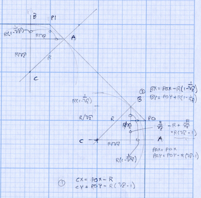
The radius on the three outside corners is a special-case solution of the general circle-through-three-points problem, taking advantage of the symmetry and right-triangle-ness of the corners. This sketch shows the details:
M2 Platform Clip Doodles 4 – corner fairing with margin
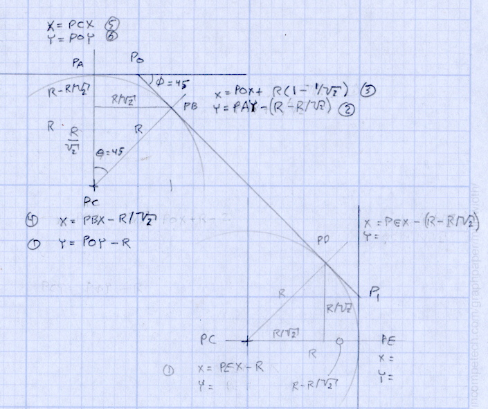
The two corners on the bevel over the glass plate have a fixed radius. I reworked my original fairing arc solution for outside cutting and doodled it up for this situation:
M2 Platform Clip Doodles 5 – bevel full solution
The outside corner radius worked out to 5 mm and I set the bevel radius at 3 mm. I think the latter made those corners a bit too sharp, but it’s Good Enough for my simple needs.
Drilling and machining the clips required a fixture:
I used cutter diameter compensation to mill the edges, starting oversize by 1.5 mm and working downward by 0.5 mm on each pass to the actual diameter. That gradually trimmed off the edges without any excitement, so I could start with rough-trimmed stock and not worry about precision hand trimming.
I thought climb milling (CW around the part) would produce better results, but it tended to smear the phosphor bronze against the fixture:
M2 Corner Clips – Climb milling tool paths
Conventional milling (CCW around the part) actually worked, but it required fancier entry and exit moves:
M2 Corner Clips – Conventional milling tool paths
This part is the kind and size of machining perfectly suited to a Sherline CNC mill…
The LinuxCNC G-Code source:
( M2 Build Platform Corner Clips )
( Ed Nisley - KE4ZNU - July 2013 )
( Fixture origin at right-front corner pip )

( Flow Control )
#<_Do_Drill> = 0		( Drill two holes in clip )
#<_Do_Mill> = 1			( Mill clip outline )
#<_Climb_Mill> = 0		( 0 = conventional 1 = climb)

( Fixture info )
#<_Drill_X_Fixture> = 5.0	( Drill station origin )
#<_Drill_Y_Fixture> = 5.0

#<_Drill_Num> = 30			( Drill number in tool table)
#<_Drill_Retract> = 15
#<_Drill_Depth> = -1.0
#<_Drill_Feed> = 300
#<_Drill_Speed> = 3000

#<_Mill_X_Fixture> = 40.0	( Mill station origin )
#<_Mill_Y_Fixture> = 5.0

#<_Mill_Num> = 3			( Mill number in tool table)
#<_Mill_Dia> = 4.60			( actual tool diameter)
#<_Mill_Dia_Incr> = 0.50
#<_Mill_Dia_Steps> = 3
#<_Mill_Retract> = 15
#<_Mill_Depth> = -0.5
#<_Mill_Feed> = 300
#<_Mill_Speed> = 8000

(----------------)

(  Initialize first tool length at probe switch )
(     Assumes G59.3 is still in machine units, returns in G54 )
(  ** Must set these constants to match G20 / G21 condition! )

#<_Probe_Speed>     = 400            ( set for something sensible in mm or inch )
#<_Probe_Retract>   =   1            ( ditto )

O<Probe_Tool> SUB

G49                     ( clear tool length compensation )
G30                     ( move above probe switch )
G59.3                   ( coord system 9 )

G38.2 Z0 F#<_Probe_Speed>           ( trip switch on the way down )
G0 Z[#5063 + #<_Probe_Retract>]     ( back off the switch )
G38.2 Z0 F[#<_Probe_Speed> / 10]    ( trip switch slowly )

#<_ToolZ> = #5063                    ( save new tool length )

G43.1 Z[#<_ToolZ> - #<_ToolRefZ>]    ( set new length )

G54                     ( coord system 0 )
G30                     ( return to safe level )

O<Probe_Tool> ENDSUB

(-------------------)
(-- Initialize first tool length at probe switch )

O<Probe_Init> SUB

#<_ToolRefZ> = 0.0      ( set up for first call )

O<Probe_Tool> CALL

#<_ToolRefZ> = #5063    ( save trip point )

G43.1 Z0                ( tool entered at Z=0, so set it there )

O<Probe_Init> ENDSUB

(-------------------)
(-- Mill one pass around outline with tool diameter passed in #1 )

O<MillOutline> SUB

#<X_Size> = 22.0		( size of support spider pad = nominal clip size )
#<Y_Size> = 22.0
#<Base_Bevel> = 3.2		( X or Y length of corners clipped from spider pad )

#<Bevel_Size> = 9.0		( remaining part of trimmed edges on clip )
#<Bevel_Radius> = 3.0	( fairing radius at bevel corners on clip)

#<R_Div_Root2> = [#<Bevel_Radius> / SQRT[2]]
#<R_1M_Recip_R2> = [#<Bevel_Radius> * [1 - 1/SQRT[2]]]
#<R_Root2_M1> = [#<Bevel_Radius> * [SQRT[2] - 1]]

#<Margin> = 0.5			( recess inside of nominal )

#<X_Min> = [#<Margin>]
#<X_Max> = [#<X_Size> - #<Margin>]

#<Y_Min> = [#<Margin>]
#<Y_Max> = [#<Y_Size> - #<Margin>]

#<Corner_Rad> = [[#<Margin> * [1 - SQRT[2]] + [#<Base_Bevel> / SQRT[2]]] / [SQRT[2] - 1]]

O<Climb> IF [#<_Climb_Mill>]

G0 X#<X_Min> Y[#<Y_Max> + 3*#<_Mill_Dia>]
G1 Z#<_Mill_Depth> F#<_Mill_Feed>

G41.1 D#1

G3 X[#<X_Min>] Y#<Y_Max> I0 J[0-1.5*#<_Mill_Dia>]	( cutter comp on: entry move)

G1 X[#<Bevel_Size> - #<R_Root2_M1>]
G2 X[#<Bevel_Size> + #<R_1M_Recip_R2>] Y[#<Y_Max> - #<R_1M_Recip_R2>] J[0-#<Bevel_Radius>]

G1 X[#<X_Max> - #<R_1M_Recip_R2>] Y[#<Bevel_Size> + #<R_1M_Recip_R2>]
G2 X#<X_Max> Y[#<Bevel_Size> - #<R_Root2_M1>] I[0-#<R_Div_Root2>] J[0-#<R_Div_Root2>]

G1 Y[#<Y_Min> + #<Corner_Rad>]
G2 X[#<X_Max> - #<Corner_Rad>] Y#<Y_Min> I[0-#<Corner_Rad>] J0

G1 X[#<X_Min> + #<Corner_Rad>]
G2 X#<X_Min> Y[#<Y_Min> + #<Corner_Rad>] I0 J#<Corner_Rad>

G1 Y[#<Y_Max> - #<Corner_Rad>]
G2 X[#<X_Min> + #<Corner_Rad>] Y#<Y_Max> I#<Corner_Rad> J0

G40

G0 X#<X_Min> Y[#<Y_Max> + 3*#<_Mill_Dia>]
(G3 X#<Bevel_Size> Y[#<Y_Max> + 3*#<_Mill_Dia>] I0 J[1.5*#<_Mill_Dia>])	( cutter comp off: safe exit)

G0 X#<X_Min>			( return to start)

O<Climb> ELSE

G0 X#<X_Size> Y[#<Y_Size> + #1/2]

G1 Z#<_Mill_Depth> F#<_Mill_Feed>

G42.1 D#1

G1 X#<Bevel_Size> Y[#<Y_Max>]	( cutter comp on: entry move)

G1 X[#<X_Min> + #<Corner_Rad>]
G3 X#<X_Min> Y[#<Y_Max> - #<Corner_Rad>] I0 J[0-#<Corner_Rad>]

G1 Y[#<Y_Min> + #<Corner_Rad>]
G3 X[#<X_Min> + #<Corner_Rad>] Y[#<Y_Min>] I#<Corner_Rad> J0

G1 X[#<X_Max> - #<Corner_Rad>]
G3 X[#<X_Max>] Y[#<Y_Min> + #<Corner_Rad>] I0 J#<Corner_Rad>

G1 Y[#<Bevel_Size> - #<R_Root2_M1>]
G3 X[#<X_Max> - #<R_1M_Recip_R2>] Y[#<Bevel_Size> + #<R_1M_Recip_R2>] I[-#<Bevel_Radius>]

G1 X[#<Bevel_Size> + #<R_1M_Recip_R2>] Y[#<Y_Max> - #<R_1M_Recip_R2>]
G3 X[#<Bevel_Size> - #<R_Root2_M1>] Y#<Y_Max> I[-#<R_Div_Root2>] J[-#<R_Div_Root2>]

G2 Y[#<Y_Max> + 3*#<_Mill_Dia>] J[#<_Mill_Dia>*1.5]		( get away from corner)
G40

G0 X#<X_Size>					( cutter comp off: safe exit)
G0 Y[#<Y_Size> + #1/2]			( return to start)

O<Climb> ENDIF

O<MillOutline> ENDSUB

(----------------)
( Start machining... )

G17 G40 G49 G54 G80 G90 G94 G99	( reset many things )

G21								( metric! )
G91.1 							( incremental arc centers)

(msg,Verify: G30.1 position in G54 above tool change switch? )
M0
(msg,Verify: fixture origin XY touched off? )
M0
(msg,Verify: Current tool Z=0 touched off? )
M0

( Set up probing)
O<Probe_Init> CALL
T0 M6

(---- Drill holes)

O<DoDrill> IF [#<_Do_Drill>]

(debug,Insert drill tool = #<_Drill_Num>)
T#<_Drill_Num> M6
O<Probe_Tool> CALL
(debug,Set spindle to #<_Drill_Speed> rpm )
M0

G0 X#<_Drill_X_Fixture> Y#<_Drill_Y_Fixture>
G0 Z#<_Drill_Retract>

G10 L20 P2 X0 Y0 Z#<_Drill_Retract>	( P2 = G55)
G55					( drill station coordinates )

G81 X5.0 Y15.0 Z#<_Drill_Depth> R#<_Drill_Retract> F#<_Drill_Feed>

G81 X15.0 Y5.0

G54

O<DoDrill> ENDIF

(---- Mill outline )
( Start with large diameter and end with actual diameter to trim in stages)

O<DoMill> IF [#<_Do_Mill>]

(debug,Insert mill tool = #<_Mill_Num>)
T#<_Mill_Num> M6
O<Probe_Tool> CALL
(debug,Set spindle to #<_Mill_Speed> rpm )
M0

G0 X#<_Mill_X_Fixture> Y#<_Mill_Y_Fixture>
G0 Z#<_Mill_Retract>

G10 L20 P2 X0 Y0 Z#<_Mill_Retract>	( P2 = G55)
G55					( mill station coordinates )

#<PassCount> = 0

O<MillLoop> DO
#<Diameter> = [#<_Mill_Dia> + [#<_Mill_Dia_Steps> - #<PassCount>]*#<_Mill_Dia_Incr>]

O<MillOutline> CALL [#<Diameter>]

#<PassCount> = [#<PassCount> + 1]
O<MillLoop> WHILE [#<PassCount> LE #<_Mill_Dia_Steps>]

( Finishing pass with zero cut )
O<MillOutline> CALL [#<Diameter>]

G0 Z#<_Mill_Retract>
G54

O<DoMill> ENDIF

G30

(msg,Done!)
M2
The rest of the doodles, which don’t match up with the final G-Code because they represent the earliest versions of the layout:
It should be possible to sense the filament diameter with a cheap webcam and some optics:
Filament Diameter Sensor – Optical Path Layout
The general idea:
Given that LinuxCNC runs on a bone-stock PC, you can plug in a stock USB webcam and capture pictures (I have done this already). Because LinuxCNC isolates the motion control in a hard real time process, you can run heavy metal image manipulation code in userland (think ImageMagick) without affecting the motors.
So you can put a macro lens in front of a webcam (like that macro lens holder) and mount it just above the extruder with suitable lighting to give a high-contrast view of the filament. Set it so the filament diameter maps to about 1/4 of the width of the image, for reasons explained below.
For a crappy camera with 640×480 resolution, this gives you 160 pixel / 1.75 mm filament = 91 pixel/mm → about 0.01 mm resolution = 0.6%. Use a better camera, get better resolution: 1280 pixel = 0.3% resolution.
That gives you roughly 1% or 0.5% resolution in area. This is pretty close to the holy grail for DIY filament diameter measurement.
Add two first-surface mirrors / prisms aligned at right angles, so that the camera sees three views of the filament: straight on, plus two views at right angles, adjacent to the main view. Set the optics so they’re all about 1/4 of the image width, to produce an image with three parts filament and one part high-contrast background separating them. This is the ideal, reality will be messier.
Figure 1 shows an obvious arrangement, the mirrors in Figure 2 give more equal distances.
You could align the mirrors to provide three views at mutual 120° angles, which would equalize the distances and give you three identical angles for roundness computation, should that matter.
Diameter measurement process:
Extract one (*) scan line across the image.
Convert to binary pixels: 1 = filament, 0 = background, perhaps with ImageMagick auto thresholding.
Add pixel values across the line, divide by 3, multiply by mm/pixel → average filament diameter.
Done!
Adding binary pixels is easy: it’s just the histogram, which ImageMagick does in one step. Dump data to a file / pipe, process it with Python. It all feeds into a LinuxCNC HAL component, which may constrain the language to C / Python / something else.
(*) You can get vertical averaging over a known filament length, essentially for free. Extract three (or more) scan lines, process as above, divide by 3 (or more), and you get a nicely averaged average.
Win: the image is insensitive to position / motion / vibration within reasonable limits, because you’re doing the counting on pixel values, not filament position. The camera can mount near, but not on, the extruder, so you can measure the filament just above the drive motor without cooking the optics or vibrating the camera to death.
Win: it’s non-contacting, so there’s not much to get dirty
Win: you get multiple simultaneous diameter measurements around one slice of the filament
You could mount the camera + optics at one end of the printer’s axis (on the M2, the X axis). Drive the extruder to a known X position, take a picture of the straight-on view, drive to another position, take a picture of the mirrored views, and you have two pictures in perfect focus. Combine & process as above.
You can do that every now and again, because any reasonable filament won’t vary that much over a few tens of millimeters. Maybe you do it once per layer, as part of the Z step process?
You could generalize this to a filament QC instrument that isn’t on the printer itself: stream the filament from spool to spool while measuring it every 10 mm, report the statistics. That measurement could run without stopping, because you don’t reposition the filament between measurements: it’s all fixed-focus against a known background. You could have decent roller guides for the filament to ensure it’s in a known position.
Heck, that instrument could produce a huge calibration file that gives diameter / roundness vs. position along the entire length of the filament. Use it to accept/reject incoming plastic supplies or, even better, feed the data into the printer along with the spool to calibrate the extrusion on the fly without fancy optics or measurements.
Dan wonders if this might be patented. I’m sure it is: I’m nowhere near as bright as the average engineering bear at a company that’s been spending Real Money for three decades. My working assumption: all the knowledge is out there, behind a barrier I can’t see through or reach around: there’s no point in looking for it beyond a casual Google search on the obvious terms that, so far, hasn’t produced anything similar.
Memo to Self: Might even be marketable, right up until they crush me like a bug…
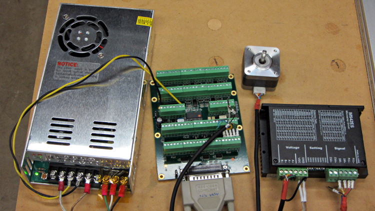
The cables with their tidy terminations make it a little neater, but all this stuff really needs a permanent home:
Stepper motor – first motion
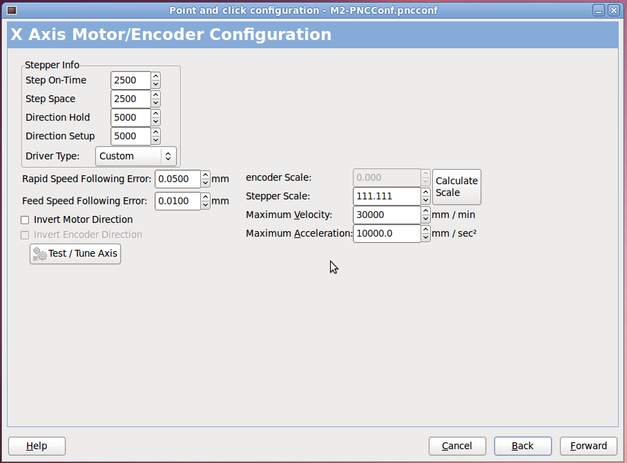
I used the LinuxCNC PNCConf utility to define a minimal system with little more than the X axis parameters filled in:
PNCConf – X Axis
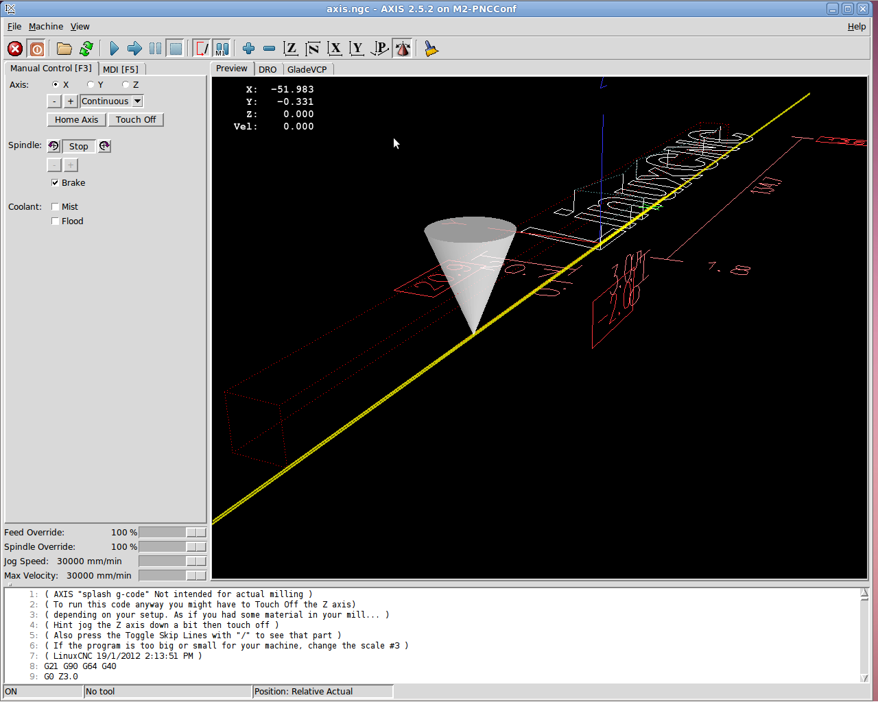
Then I could jog the stepper motor using the Axis UI:
7i76 – First Motion
And it worked!
Actually, it didn’t. The first motion instantly tripped a Following Error, so I bumped those values up a bit. Then I fiddled with accelerations and speeds and suchlike. Then I adjusted the Axis defaults to not be so nose-pickin’ slow. And then it Just Worked.
Not much to show, but at least I know the whole LinuxCNC to 5i25 to 7i76 to M542 to motor chain functions pretty much as it should, which is worth knowing. From here on out, it’s a matter of fine tuning…