Ed Nisley's Blog: Shop notes, electronics, firmware, machinery, 3D printing, laser cuttery, and curiosities. Contents: 100% human thinking, 0% AI slop.
Category: Science
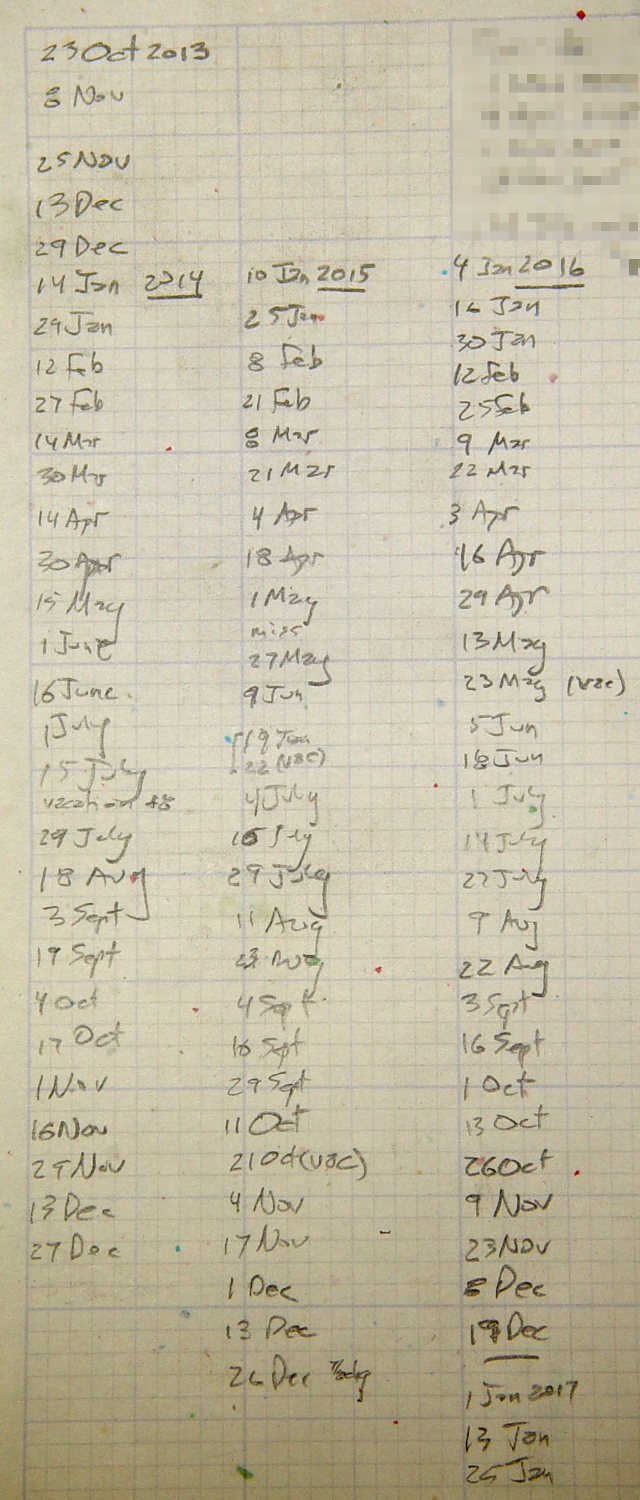
If you measure something often enough, it becomes science
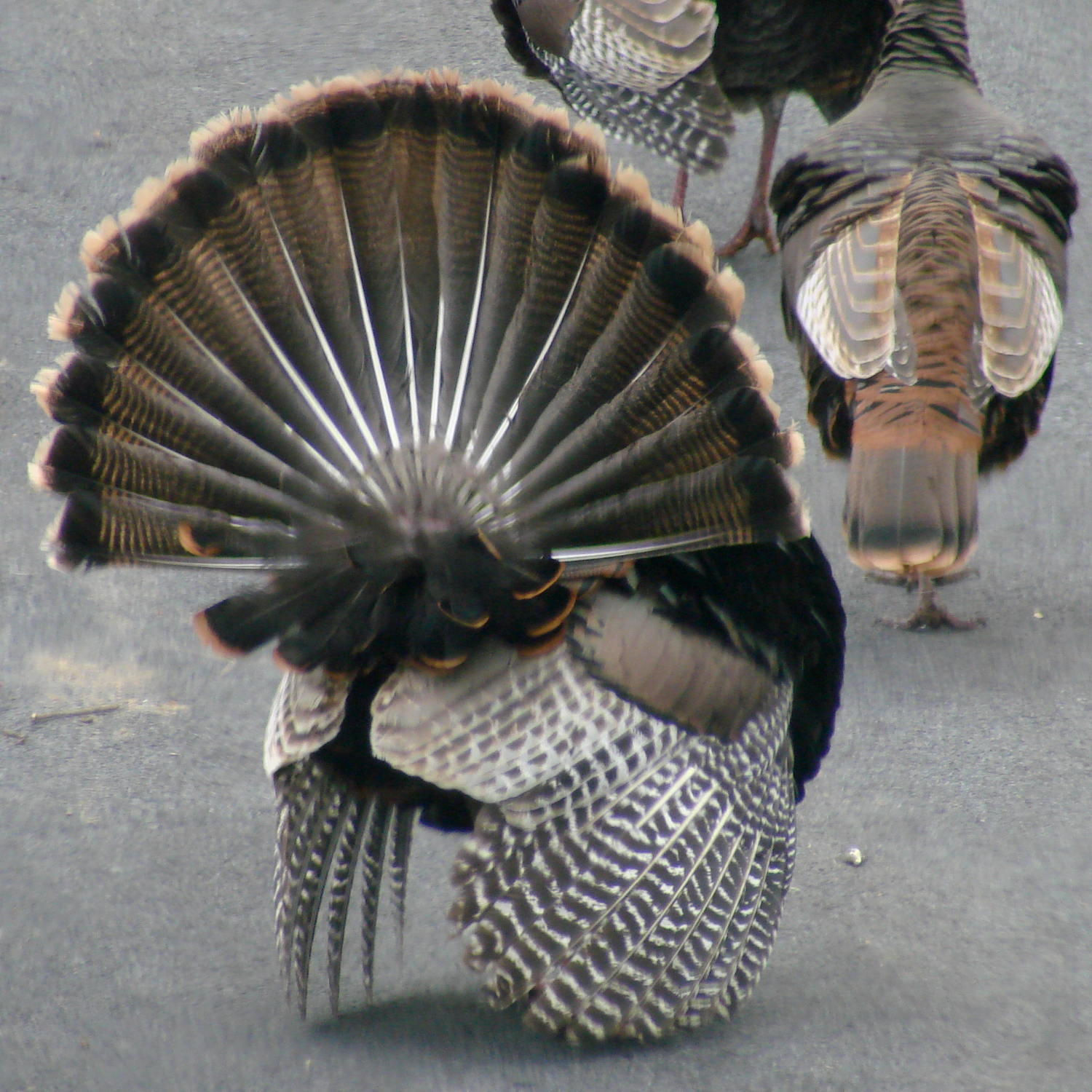
Early spring brings out large turkey flocks and provides a window into their otherwise rather private lives.
Despite all the strutting and posturing by the males, the ladies call the shots. When we see a hen go hull-down like this, we know what’s about to happen:
Turkey mating – invitation
Getting into the right position seems remarkably awkward and requires some cooperation:
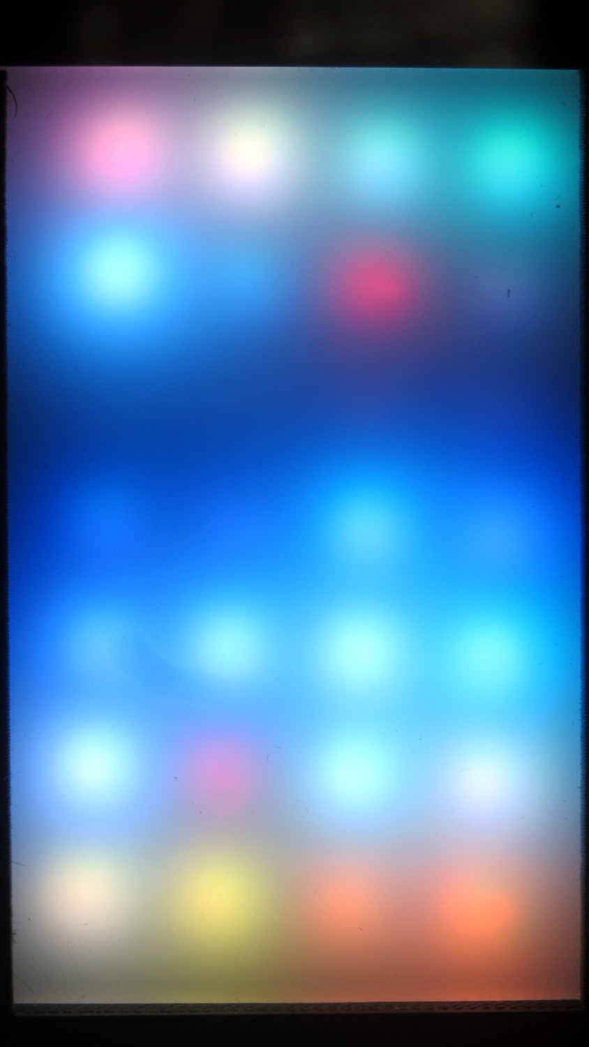
The red pixel in the second row from the top sends pinball panic to the six downstream LEDs (left and upward). Of course, it’s not consistently bad and sometimes behaves perfectly. The dark row below it contains perfectly good LEDs: they’re in a dark-blue part of the cycle.
The first WS2812 failed after about a week. This one lasted 7 weeks = 50-ish days.
The encapsulation seal went bad on this one and, for whatever it’s worth, the remainder still pass the Sharpie test. Perhaps the LEDs fail only after heat (or time-at-temperature) breaks the seal. Assuming, equally of course, the seal left the factory in good order, which seems a completely unwarranted assumption.
Anyhow, the original cells crapped out after 2-½ years, when these still delivered 13 days. After 4-½ years, they’re lasting 12 days between charges.
Color me surprised, because they’re 600 mA·h NiMH cells. The originals were 2000 mA·h cells, which you’d expect would last longer, but noooo.
No reason to change them yet, which is good news.
FWIW, I recently bought some cheap brush heads from the usual low-end eBay seller. The OEM brushes have colored bristles which fade to tell you when to change brushes, although I run ’em quite a bit longer than that. The cheap replacements have never-fading colored bristles and, I suspect, all the bristles are much too stiff. The dental hygienist says I’m doing great, so it’s all good.
Sonicare brush heads – cheap vs OEM
High truth: at best, you get what you pay for.
(*) Being that type of guy has some advantages, if you’re that guy. Otherwise, it’s a nasty character flaw.
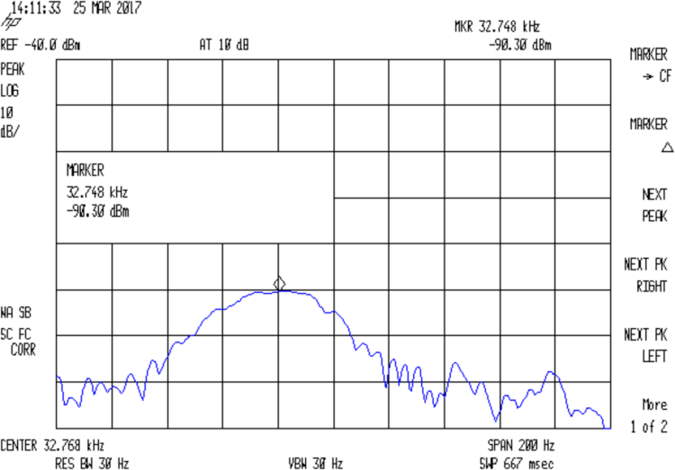
The HP 8591 tracking generator doesn’t go below 100 kHz, so I used the FG085 DDS function generator as a source. I trust the 8591’s calibration more than the FG805’s, but right now I’m more interested in the differences between successive frequencies and the DDS can step in 1 Hz increments.
The output appears on the 8591, with a big hump comes from the analyzer’s 30 Hz IF filter response sweeping across what’s essentially a single-frequency input. The hump is not the crystal’s response spectrum!
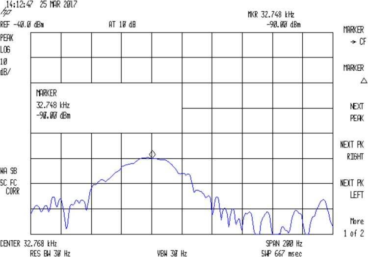
With the jumper installed to short the 33 pF cap, the output peaks at 32.764:
Quartz Resonator 32.763 kHz – no cap
Quartz Resonator 32.764 kHz – no cap
Quartz Resonator 32.765 kHz – no cap
Quartz Resonator 32.766 kHz – no cap
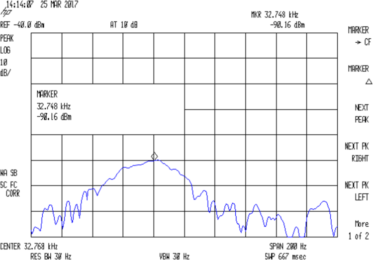
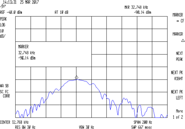
Removing the jumper to put the cap in the circuit, the response peaks at 32.765 kHz:
Quartz Resonator 32.763 kHz – 34.6 pF
Quartz Resonator 32.764 kHz – 34.6 pF
Quartz Resonator 32.765 kHz – 34.6 pF
Quartz Resonator 32.766 kHz – 34.6 pF
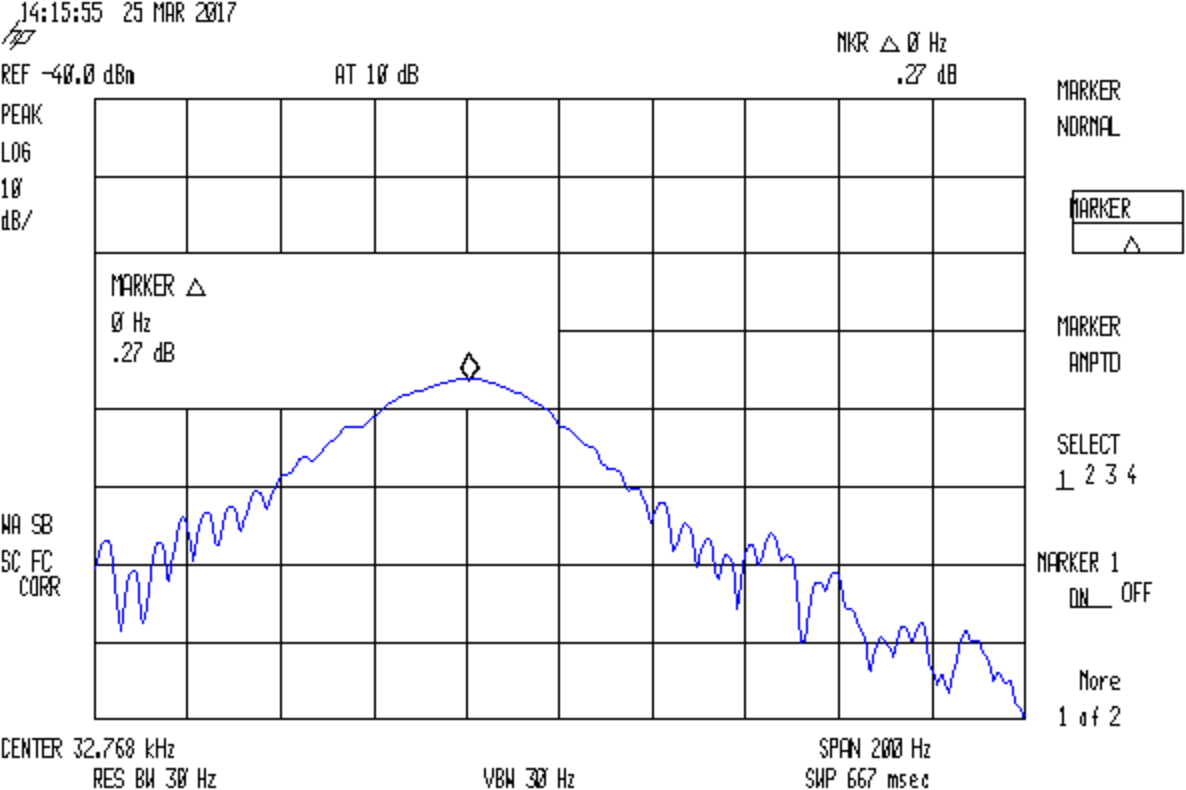
The marker delta shows the difference between the two peaks, ignoring their 1 Hz difference:
Quartz Resonator 32.764-5 no-34.6 pF delta
So I’d say the cap really does change the resonator series resonance by just about exactly 1 Hz.
With the jumper installed to remove the cap from the circuit, setting the reference marker at the 32.764 kHz peak, and measuring the relative response at 32.765 kHz :
Quartz Resonator 32.764-5 no cap delta
So the response peak is much much narrower than 1 Hz: being off-peak by 1 Hz knocks 13-ish dB from the response.
What’s painfully obvious: my instrumentation is totally inadequate for crystal measurements at these frequencies!
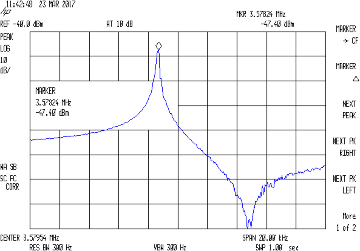
The reference level is -40 dBm, not the usual 0 dBm, due to the loss in those resistive pads. Unsurprisingly, the parallel resonance valley looks pretty ragged at -120 dBm = 1 nW = 7 µV.
Remove the jumper to put the capacitor in series:
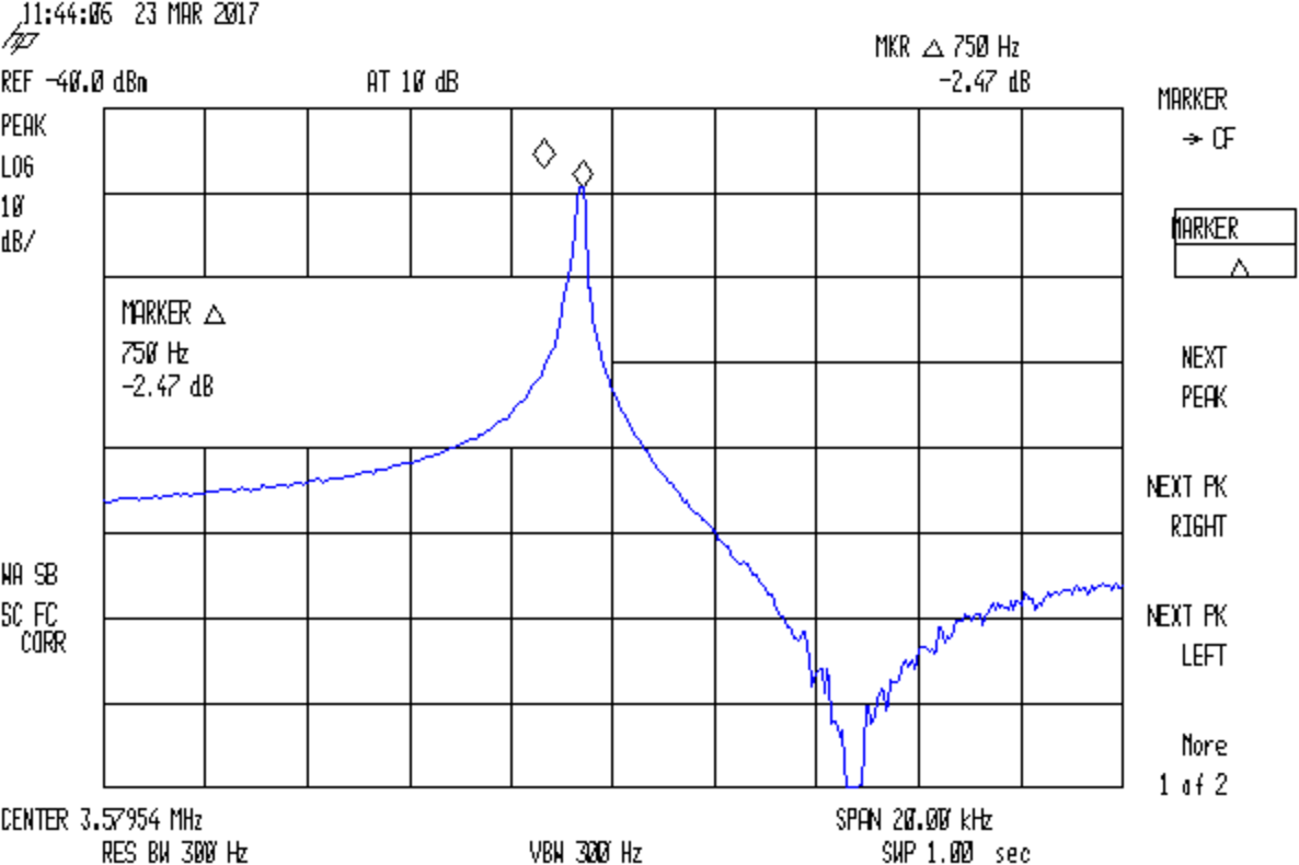
Quartz 3.57954 MHz – 36.4pF
The marker delta resolution surely isn’t 1 Hz, but 750 Hz should get us in the right ballpark.
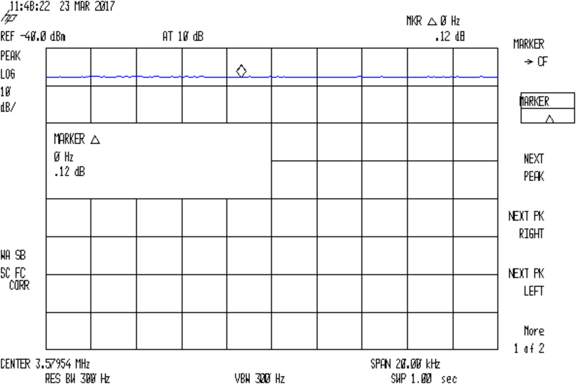
Substituting a 72 Ω resistor, found by binary search rather than twiddling a pot:
Quartz 3.57954 MHz – 72ohm
Which gives us all the measurements:
Fs = 3.57824 MHz
Fc = Fs + 750 Hz = 3.57899 MHz
Rm = 72 Ω
C0 = 3.83 pF
Cpar = 3.70 pF
Turn the crank and the crystal motional parameters pop out:
Attach scope probes to its data input and output pins (with the fixture face-down on the bench):
WS2812 LED – fixture probing
The output no longer comes from the Land of Digital Signals:
WS2812 Array Fail 1 – in vs out
I immediately thought the broken bits occupied the first 24 bit times, when the WS2812 controller should be absorbing those bits from the incoming stream. The vertical cursors show the failed bits occupy 54 µs = 40-ish bit times at 800 kHz (or you can count them), so it’s worse than a simple logic failure.
A closer look:
WS2812 Array Fail 1 – in vs out – detail
At least for those bits, neither output transistor works well at all. On the other paw, the output shouldn’t even be enabled for the first 24 bits, so there’s that to consider.
You may recall it passed the leak test shortly before I assembled the test array a month ago. Evidently, just few days of operation suffices to wreck the seal, let air / moisture into the package, and kill the controller. Not a problem you’d find during a production-line test (assuming there is such a thing), but it should certain appear during the initial design & production qualification test phase (another assumption).
Weirdly, a day after taking that photo, the controller began working perfectly again and the LEDs look just like they should: there is no explaining that!
The red spot in the next-to-bottom row of the test fixture (*) marks a failed WS2812 LED. All of the LEDs above it, plus the LED just to its left, are in pinball panic mode: random colors flicker across the panel as the LED’s controller transmits garbled data and the downstream LEDs pass it on.
This failure provides several bits of information:
The LED sees the same power supply as all the rest, so it’s not a power thing
The LED gets data from the adjacent WS2812, so it’s not an Arduino output thing
It failed after about four days = 100 hours of continuous operation
I connected the previous LED’s output (#6) to the next one’s input (#8), so the failed LED (#7, now with output disconnected) continues to flicker, but doesn’t influence any of the downstream LEDs.
(*) The LEDs are daisy-chained from lower right to upper left, row by row, so that’s LED #7 of 28.