Ed Nisley's Blog: Shop notes, electronics, firmware, machinery, 3D printing, laser cuttery, and curiosities. Contents: 100% human thinking, 0% AI slop.
Category: Science
If you measure something often enough, it becomes science
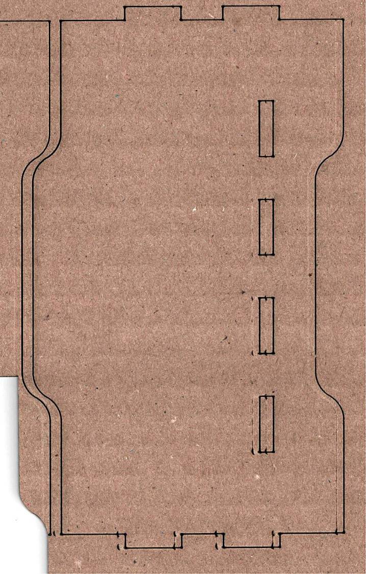
The mounting block under the electronics box for the new UPP battery has a recess for an M5 tee nut:
UPP Battery Mount – Block 5 Show View
As with the Terry frame mounts, I glued the modified tee nut in place with JB Plastic Bonder urethane adhesive, did a test fit on the bike, discovered the whole affair had to sit about 10 mm forward, put the new frame measurement into the OpenSCAD code, and ran off a new block.
Which gave me the opportunity to perch the old block atop the bench vise with the tee nut aimed downward between the open jaws, run an M5 bolt into the nut, and give it a good thwack with a hammer:
UPP Battery Mount – M5 insert adhesive test
Although the urethane adhesive didn’t bond uniformly across the tee nut, it had enough grip to tear the PETG layers apart and pull chunks out of the block.
As with the tee nuts on the Terry bike, this one will be loaded to pull into the block, so it will never endure any force tending to pull things apart, but it’s nice to know how well JB Plastic Bonder works.
I chiseled the PETG and adhesive debris off the tee nut, cleaned it up, slathered more Bonder on the new block, and squished the nut in place. After I get the electronics box sorted out, the whole affair will never come apart again!
That’s the standard backlash test pattern shrunken down to a little over an inch wide, with the laser power reduced to the bare minimum. Despite that, the numerous holes show where the pattern concentrates enough energy to vaporize the paper.
The “paper” seems to be laminated between two black plastic sheets that smell terrible when engraved, so they’re probably some form of acrylic. The Amazon product description is, despite all the verbiage- remarkably uncommunicative of the actual materials involved.
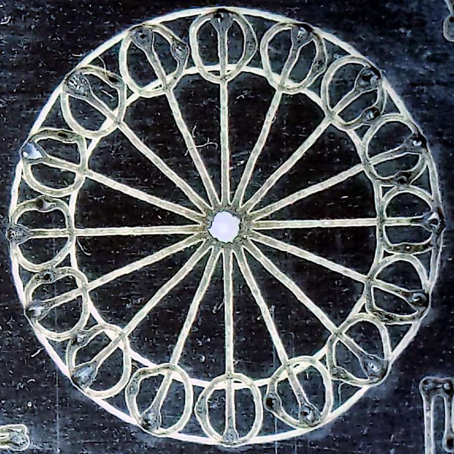
The circular pattern is 10 mm diameter on the outside:
Laser test paper – miniature pattern detail
Those should be circles around the perimeter, but their distortion shows what happens when you try to move a hulking CO₂ laser head around a 1.5 mm diameter circle at 400 mm/s. Of course, the actual speed is nowhere near that fast along such tiny vectors.
The traces are about 0.2 mm wide, with obvious scorches where the beam starts and stops, which agrees reasonably well with previousmeasurements.
All in all, both the paper and the laser pattern look better than I expected, particularly as the results indicate the machine has no measurable backlash at all.
The intended cuts are the dark lines, each with a poorly defined scorch 2 mm on its left. Knowing that the nozzle is about 4 mm, this suggests the beam is off-center enough to juuuust kiss the nozzle and splash the outer part of the beam away.
Having recently spot-checked the alignment and not seen any odd behavior on another platform-spanning project, this was puzzling. Given that the laser recently survived a move from one Basement Shop to another, with plenty of jostling while standing on end, I suppose I should have been more careful.
The biggest clue was seeing the shadow lines only near the front-right corner and noting they got worse farther into the corner. This seemed like the “fourth-corner” alignment problem described by St. Sadler some years ago and covered in a more succinct recent video.
AFAICT, the problem boils down to the difficulty of precisely aligning the beam at the longest distance it travels in the front-right corner. Careful adjustment of Mirror 1, after getting everything else lined up properly, seems to be solution.
The beam is slightly off-center at Mirror 1 and only a millimeter high on Mirror 2 at either end of the gantry travel along the Y axis.
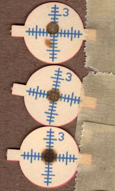
The beam position at the laser head entry upstream of Mirror 3 shows the problem:
Beam Alignment – Initial M3 entry – 2024-05-31
The targets are left- and right-rear, left- and right-front, with varying pulse lengths obviously underpowering the last and most distant shot.
Looks like a classic fourth-corner problem!
Tweaking Mirror 1 by about 1/8 turn of the adjusting screw to angle the beam vertically upward eventually put the beam dead-center at Mirror 3:
Beam Alignment – M3 adjustments – 2024-05-31
The bottom two targets are double pulses at the left- & right-rear and ‑front, so the beam is now well-centered.
A quick cross-check shows the beam remains centered on Mirror 2 at the front- and rear-end of the gantry travel, Mirror 3 is still OK, and the beam comes out of the center of the nozzle aperture:
Beam Alignment – M2 M3 exit final – 2024-05-31
Subsequent cutting proceeded perfectly all over the platform, so I think the alignment is now as good as it gets or, perhaps, as good as it needs to be.
The granular surface does not get along well with the 5× digital zoom required to fill the phone’s sensor, but you get the general idea:
Figaro TGS880 – element detail
The heater measured 30 Ω on the dot and the sensor was an open circuit on the 100 MΩ range. Connecting the heater to a 5 V supply dropped the sensor resistance to 800 kΩ @ 50 %RH and a warm breath punched it to about 2 MΩ. That’s with an ohmmeter because I haven’t yet unpacked the Electronics Bench, but seems far above the spec of 20-70 kΩ in air.
So it’s still a sensor, even if it’s not within spec.
The WordPress AI-generated image for this post is … SFnal:
Figaro TGS-880 Gas Sensor – AI generated image
My pictures apparently aren’t up to contemporary blog standards …
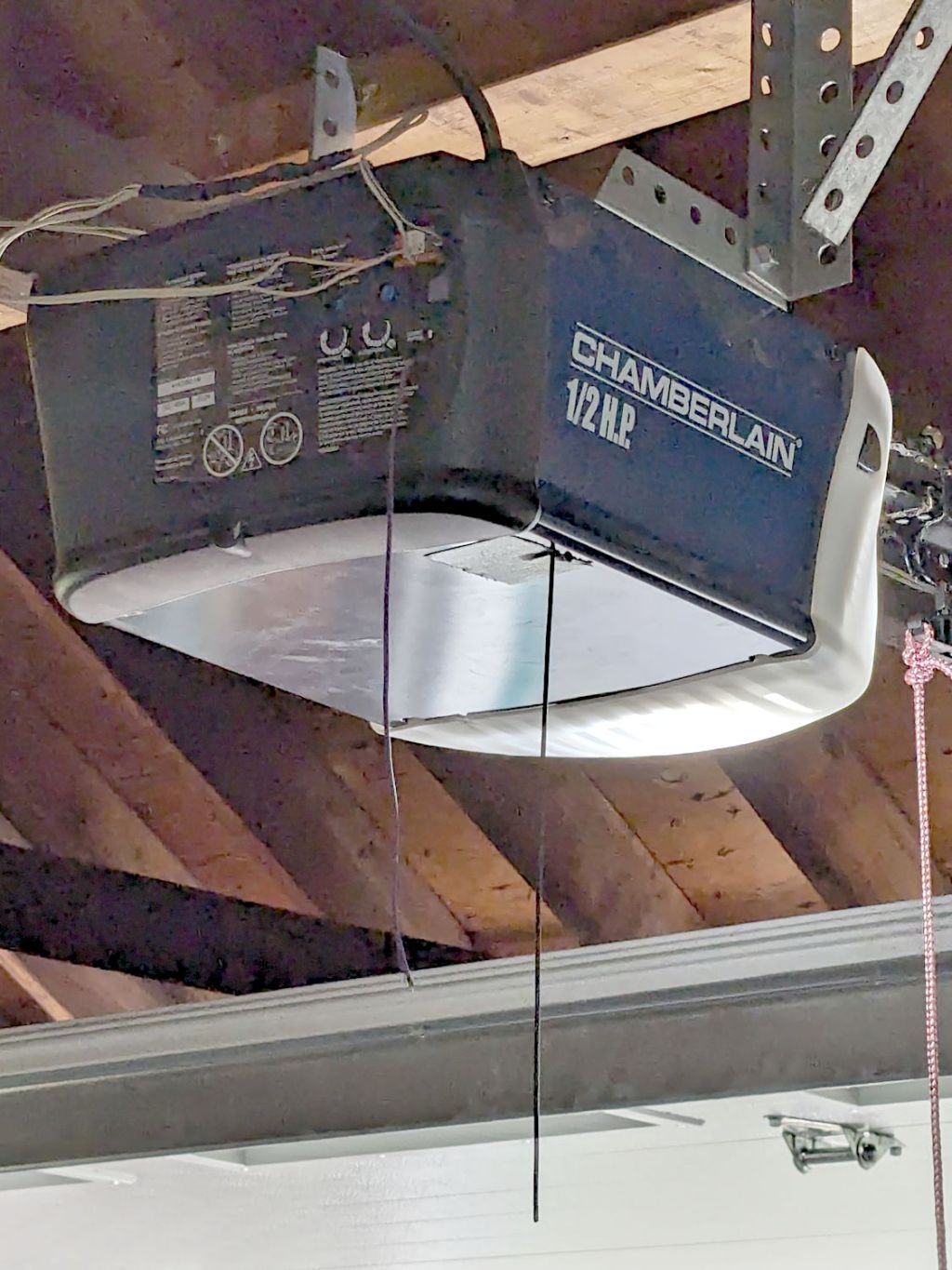
By a quirk of fate, the Chamberlain garage door opener in our new house has the same “purple learn button” as the Sears opener in our old house, so I introduced it to our remotes and they work just fine.
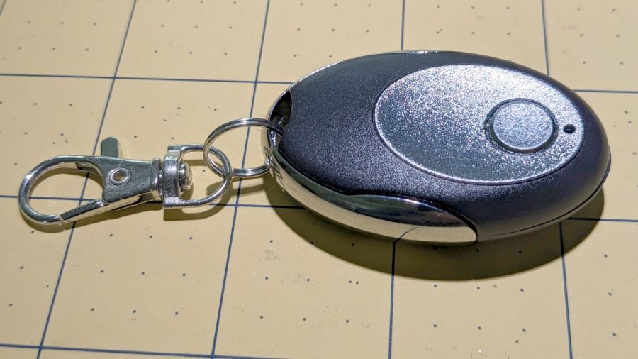
I then replaced the four-button remote in my bike pack with a new single-button remote to reduce the dexterity required to hit the button:
Garage Opener – one button
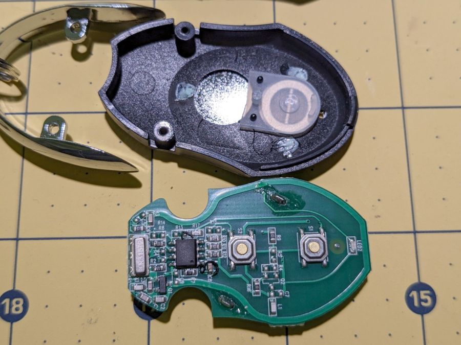
Alas, the opener only responded when the remote was immediately outside the aluminum garage door. Checking the battery (because sometimes “new” does not mean what you think it means) reminded me we live in an age when hardware is free compared with bookkeeping:
Garage Opener – interior
Maybe the second button doesn’t work and this is how they monetize their QC reject pile?
I want the door to start moving when I’m at the end of the driveway, giving it enough time to get all the way up so I can bike right in. You can actually buy remote / extension antennas, although for fancier openers with SMA antenna connectors, but sometimes a little RF black magic will suffice:
Garage Opener – crude antenna director
The wavy wire hanging down from the opener’s rear panel is the original antenna, which might be kinda-sorta omnidirectional. The opener operates around 433 MHz= 69 cm, so a quarter-wave antenna will be 17 cm = 7 inch long; the (unbent) wire is maybe 10 inches long from the hole in the panel.
So I taped 11 inches of wire to the opener to form a very very crude Yagi-Uda antenna. It’s too long to be a director element, it’s about right (albeit in the wrong place) to be a reflector element, it might be neither.
What it does do is warp the antenna’s pattern just enough to let the remote reliably trigger the opener as I approach the end of the driveway.
Do not even begin to think about polarization mismatch from what looks like the tiny loop antenna on the remote’s PCB.
The previous Basement Laboratory generally stayed above 60 °F = 15 °C, so I set the LightObject water chiller’s low-temperature alarm accordingly.
Having reached the point where I can set up the laser in its new home, I connected the chiller tubes, filled the reservoir with distilled water (and a squirt of algaecide), connected the alarm wiring, turned it on, and had the cool water trigger an alarm:
LightObject Laser chiller – low temp alarm
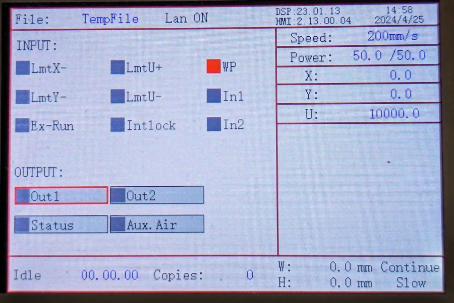
Which was relayed to the controller:
KT332N Diagnostic display – water protect active
Silencing the chiller’s alarm clears the error indicator in the controller, so it’s possible to Fire The Laser with too-cold water if necessary.
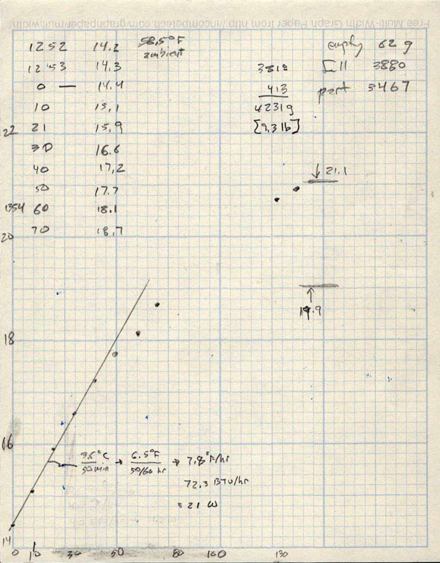
As with the previous icemaker chiller, plotting the water temperature as a function of time shows the pump adds some energy as it moves the water around the loop:
LightObject Q600 chiller – water heating
The gap in the data shows where I had a few other things to do, but the exponential rise is obvious. The chiller compressor starts at just over 21 °C and stops at just under 20 °C, so the exponential curve had gone about as far as it could go.
The numbers in the upper right of the plot give the weight of:
An empty water bottle
A full gallon bottle
The partially empty bottle used to top off the reservoir
How much water went into the chiller reservoir
The figures in the bottom mash the initial slope of that curve together with the weight of the water to find the 21 W required to heat the water at that rate, with a bank shot off British Thermal Units because why not.
A Kill-a-Watt meter shows the Q600 chiller draws 36 W with the pump running, which includes the controller and a column of blue LEDs behind the water level tube.
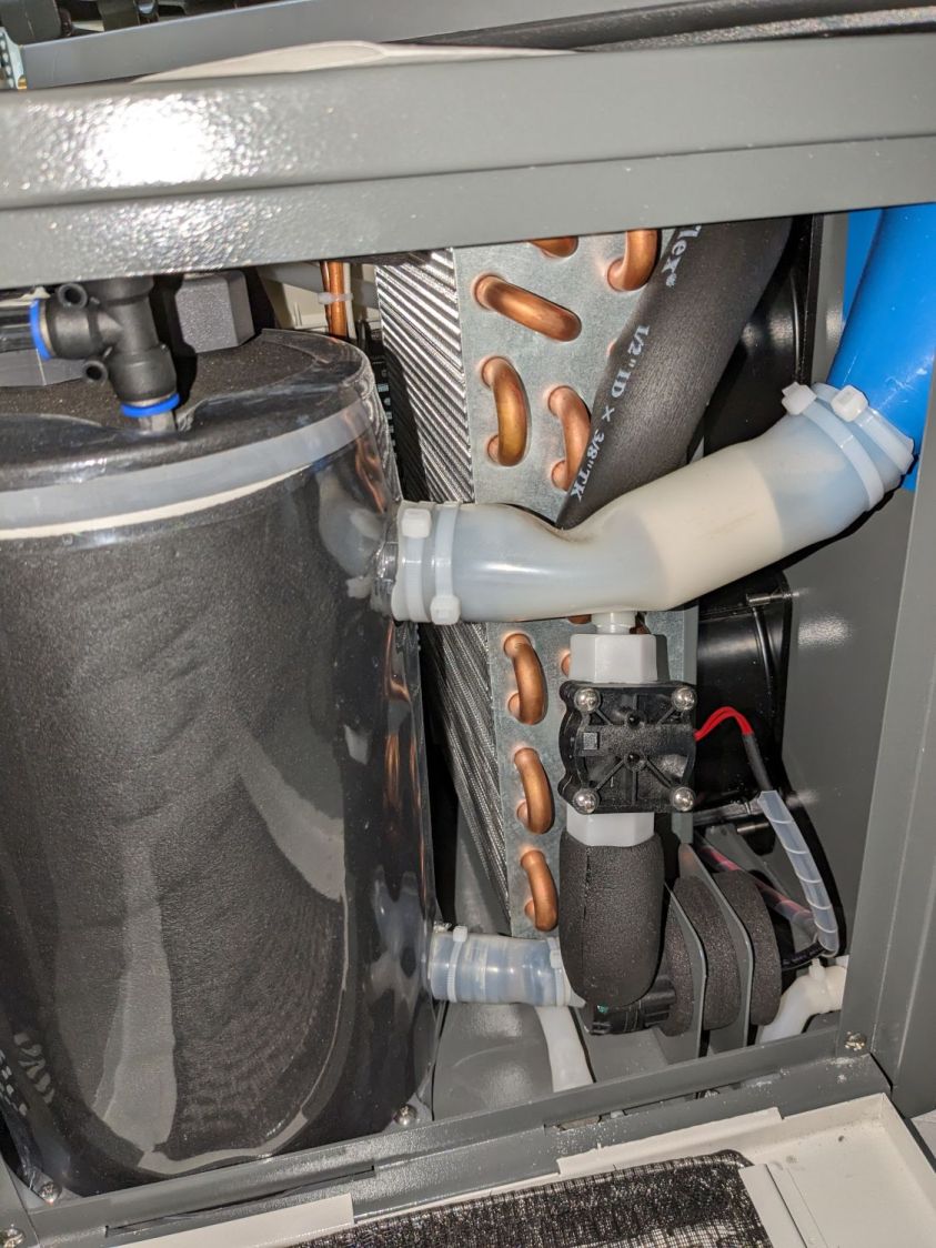
The pump (in the lower right) isn’t exactly water-cooled, but it’s not losing a lot of heat through that foam wrapper and maybe most of the heat really does come from the motor:
LightObject Laser chiller – right side internal view
The basement temperature will rise as Spring becomes Summer, so the chiller will start working right away, and it’ll definitely get more exercise when the laser starts cutting again.
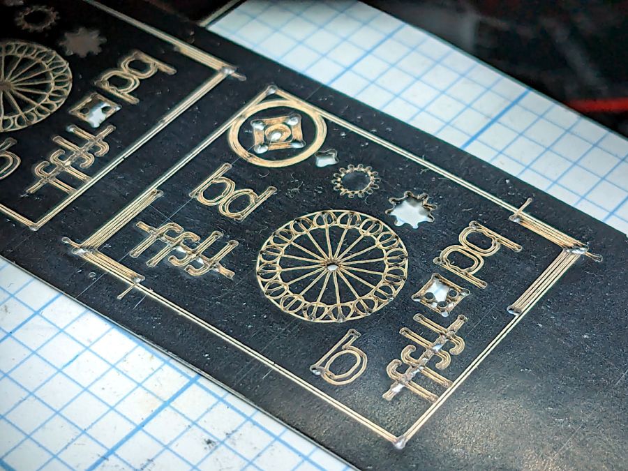
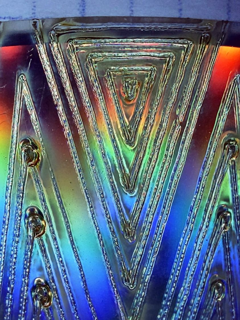
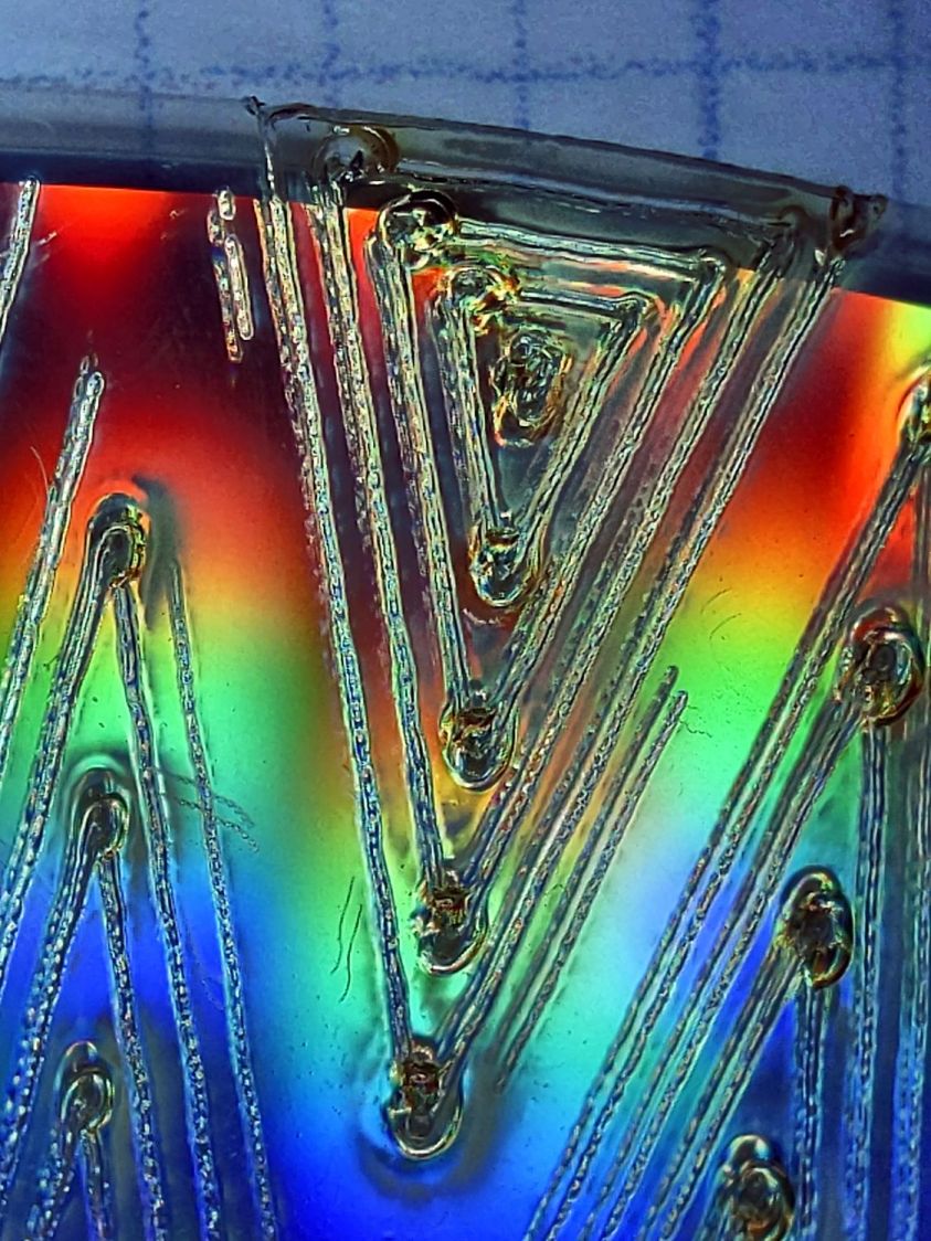
Wrecking scrap discs led to experimenting with the low-power behavior of my nominal 60 W CO₂ laser. I used the same inset version of the Mariner’s Compass quilting pattern as before:
Mariners Compass – stacked insets – LB layout
The KT332N controller is set to a 7% minimum power, as the tube simply doesn’t fire below that level. The power levels shown below are the minimum and maximum for the layer.
The cuts are on CD-R discs with the same general appearance, although I can’t say whether they all came from the same manufacturing lot. All of the cuts are on the clear side of the disc, with the data side flat against the platform. Unless otherwise noted, the pictures are from the clear side, looking down into the trenches carved into the surface, and you can see reflections of the cuts in the aluminized data layer.
Power 7 to 10%:
CD-R vector cut – clear side – 7-10pct
Because the controller uses the minimum power at lower speeds, the laser fails to fire near the corners of the pattern.
Power 8 to 10%:
CD-R vector cut – clear side – 8-10pct
The patterns generally begin in their upper-right corner where the laser has little enough power to prevent melting. However, the tube now continues firing as the laser slows for two other corners and melts a gouge into the surface.
Power 7.5 to 10%:
CD-R vector cut – clear side – 7.5-10pct
The gouges are less prominent, but not by much.
Power 7.1 to 10%:
CD-R vector cut – clear side – 7.1-10pct
Reducing the minimum power to just over the 7% absolute minimum reduces the size of (most of) the blobs, but also causes gaps in some of the lines and at the corners.
Power 7.1 to 7.5%:
CD-R vector cut – clear side – 7.1-7.5pct start
Reducing the maximum power causes the tube to not fire at all for some vectors; it doesn’t fire at all with the maximum power set to 7.1%.
However, the firing is very sensitive to the tube temperature, as that picture is for the first pattern around the disc rim with the cooling water temperature at 20.5 °C.
The last pattern (which is just to the right of the first) looks much better with the coolant at 20.7 °C:
CD-R vector cut – clear side – 7.1-7.5pct end
It’s still not complete, but you can see the tube power has increased enough to melt blobs into the surface similar to those at higher maximum powers.
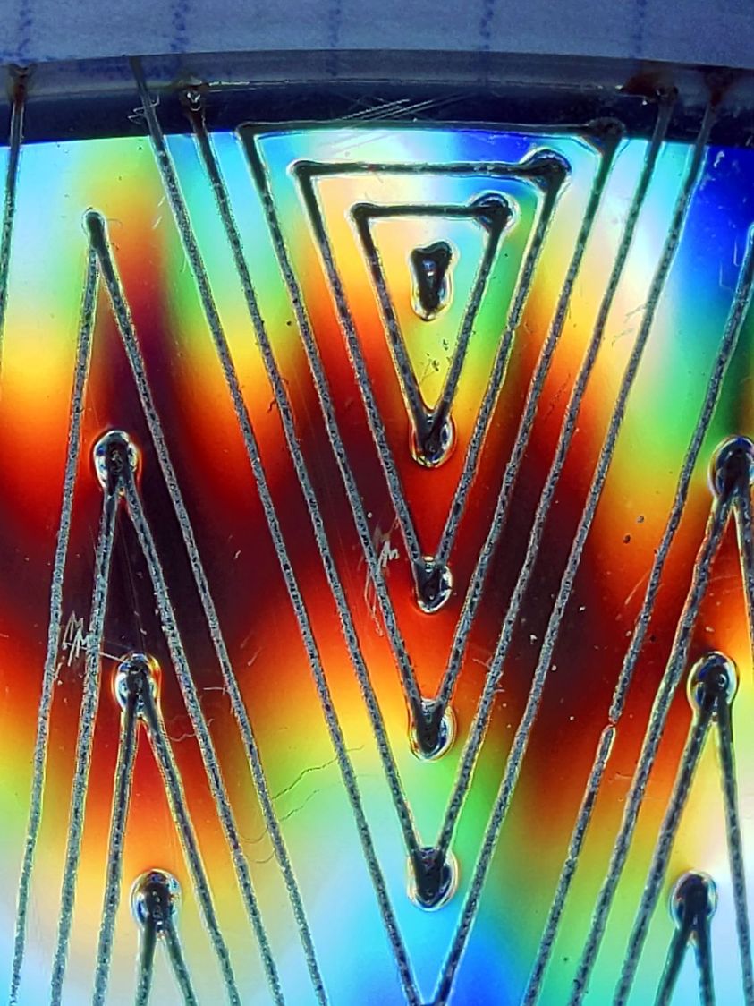
Power 7.5 to 8%:
CD-R vector cut – clear side – 7.5-8pct
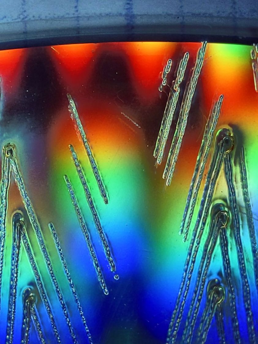
Although the tube now fires continuously throughout the pattern, you can see thinner sections in the longer vectors over on the left.
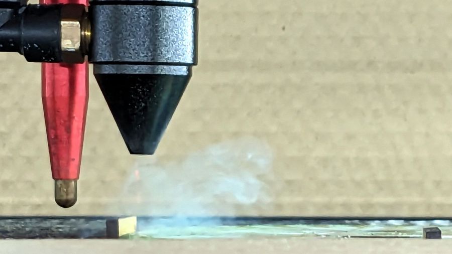
All of the pictures above are using assist air at 12 l/min, so there’s a stiff breeze blowing the smoke away from the laser beam. Turning the assist air off reduces the flow to 2 l/min and produces a much larger cloud of fumes over the surface that seems to deposit more crud around the vectors:
CD-R vector cut – 2l-min assist air
The small MDF stops jammed in the honeycomb platform let me put all the CD-Rs at the same spot and reuse the same pattern with slight power variations and no realignment. It’s not perfect, but it’s pretty good.
CD-R vector cut – clear side – 7.5-8pct low air cleaned
If you’re being fussy about cleanliness, you might avoid scratching the otherwise pristine surface.
I also burned the data side of a disc to wreck the lacquer and aluminized layer, rather than just the clear polycarbonate.
Power 7.5 to 8% on data side, as seen from the data side:
CD-R vector cut – data side – 7.5-8pct data side
The same pattern on the same disc, seen from the clear side:
CD-R vector cut – data side – 7.5-8pct clear side
Burning through the lacquer and aluminum produces a narrower trench and slightly smaller blobs at the junctions.
Running near the tube’s minimum power produces unpredictable results, because the tube temperature matters. Variations of a few tenths of a degree can prevent the tube from firing, either intermittently or completely, so keeping the minimum layer power well above the minimum tube power is a Good Idea™ unless you can afford considerable scrap.
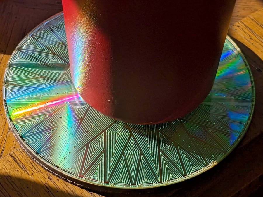
It’s a slow way to wreck discs, but a nice way to produce suncatching coasters: