Ed Nisley's Blog: Shop notes, electronics, firmware, machinery, 3D printing, laser cuttery, and curiosities. Contents: 100% human thinking, 0% AI slop.
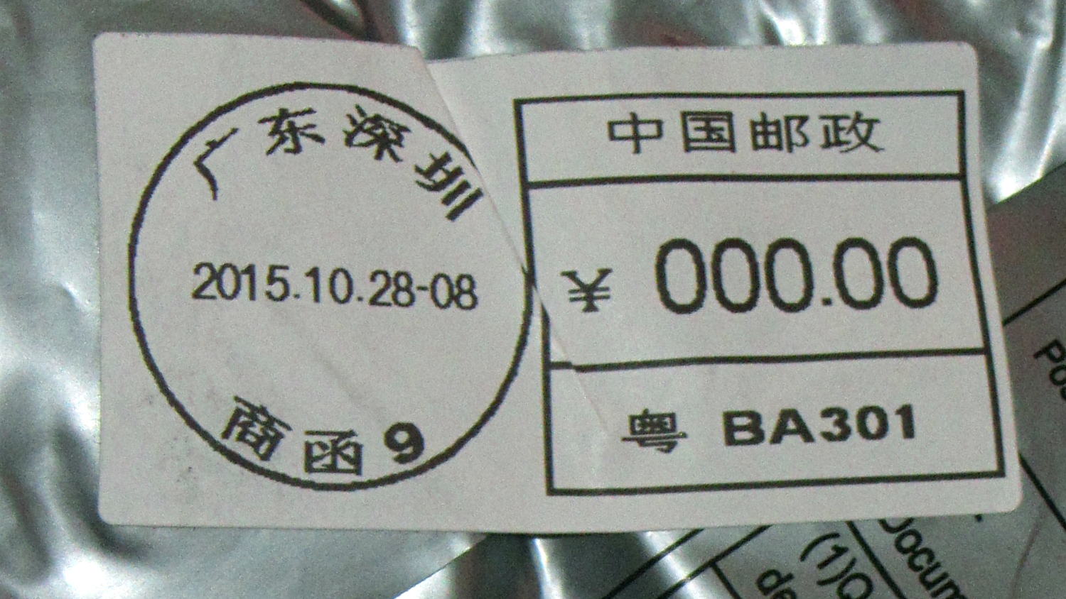
Yeah, I’m sure that’s not what it means, but, still…
I don’t understand how the total cost of a nontrivial something shipped halfway around the planet can be less than the price I’d pay to return it. I’m certain it involves massive subsidies and mysterious cash flows that never break the surface of the eBay “Buy It Now!” pond.
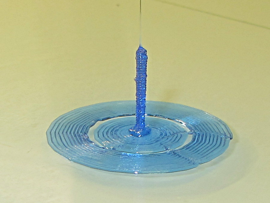
Sliced with Slic3r for PETG at 1 mm/s, with fans in full effect. It sits amid a 5 mm brim, inside a skirt that uses 15 mm of filament, giving it a Washington Monument aspect.
The challenge was to print a 0.7x9.0 cylinder, which doesn’t work well with a 0.35 mm nozzle. Instead, I went with 0.9 mm diameter. The result measures 1.1 mm over all the obvious bumps, so it’s surprisingly close. The “nail head” at the bottom most likely comes from the hot end depressurizing as it suddenly transitions from 15 mm/s in the brim to 1 mm/s for the cylinder.
Fairly obviously, you can’t print something like that at full speed (50 mm/s was claimed for a Rep 2 and I don’t believe that for an instant). Indeed, it’s such a pathological model that Slic3r’s minimum layer time and small perimeter settings had no effect; I had to manually set the extrusion speed to 1 mm/s in order to make it work. Plus adding that brim, because I knew it wouldn’t stand by itself.
Other than that, printing it was no big deal.
A picture from that M2 forum discussion suggests you can go crazy with this stuff:
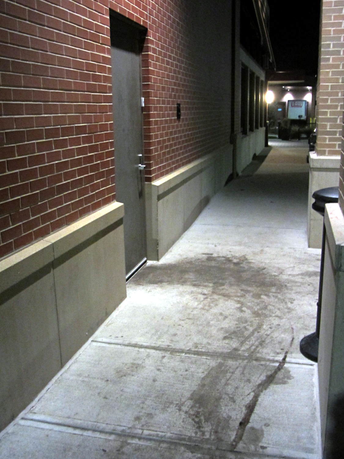
The stains appeared black-red under the cold LED light and my first thought went along the lines of “Somebody dragged a corpse out of the kitchen!”:
Restaurant back door
The dumpsters sit off the sidewalk behind me on the left, so, most likely, they just have a bit of trouble maneuvering overstuffed trash cans and grease tanks around the door. At least, that’s what we hoped.
Notice how the door hinges the wrong way? Perhaps the architect never anticipated moving waste from the kitchen to the dumpsters.
The food was OK (we did not order the Chef’s Special Long Pig), but their overly loud “background music” reverberated far too long inside a cavernous room with hard walls. We gave it 2/10: would not eat there again.
If the 1-48 on the side of the tube base (facing away in the picture) means anything, then General Electric built it in January 1948.
The pinout view in the datasheet assumes you’re looking at the bottom of the socket, which makes perfect sense given the hand-wired chassis construction techniques of the day:
0D3 Voltage Regulator Tube – pinout
So the view is backwards when seen from the top, not that you’d ever need it:
Ceramic octal tube socket – 0D3 pinout
The internal jumper across pins 3-7 allows you to disconnect the downstream circuit when the regulator isn’t in the socket, which is a Very Good Idea with a shunt regulator.
Not having a 200 V power supply ready to hand, but having recently restocked the 9 V alkaline battery box, this actually worked:
0D3 voltage regulator test setup
That’s 16 x 9-ish V = 150 V across the battery terminals, plus a 50 V adjustable bench power supply coming in on clip leads from the upper right, with current shown on a digital panel meter across a 1 Ω sense resistor. The classic 1.5 kΩ carbon resistor emerged from from a coffee can of parts that Came With The House™ and seemed appropriate for the occasion.
The tube conducts a few milliamps through a small plasma filament discharge at 150 V. The current ramps up to about 10 mA as the supply voltage increases to 180 V, whereupon the tube fires and the current jumps to 30 mA (which is less than the spec, but I ran the power supply in constant-current mode to avoid whoopsies).
Reducing the current to 10 mA slightly reduces the area involved in the plasma discharge, but the tube still produces a nice display through the mica spacer / insulator atop the plate:
0D3 voltage regulator – 10 mA current
That isn’t quite in focus, but should give you the general idea.
I didn’t measure the operating voltages across the tube, mostly because I didn’t want more cheap clip leads cluttering the bench.
It’d make a very low intensity nightlight that dissipates a watt or two. Boosting the current to the absolute maximum 40 mA would brighten it up a bit, but dissipating 6 W in the tube probably won’t do it any good.
This obviously calls for an Arduino monitoring the tube current with a Hall-effect sensor and regulating it with a hulking MOSFET…