What with punching the Apollo 11 CSM source code into the cards, converting the mission’s eagle into a layered shape made some sense.
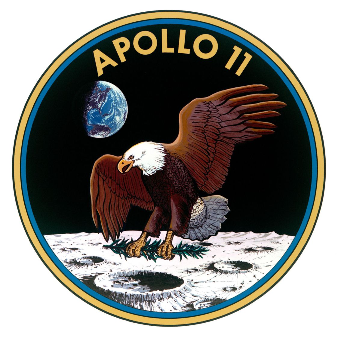
The original Apollo 11 mission patch:
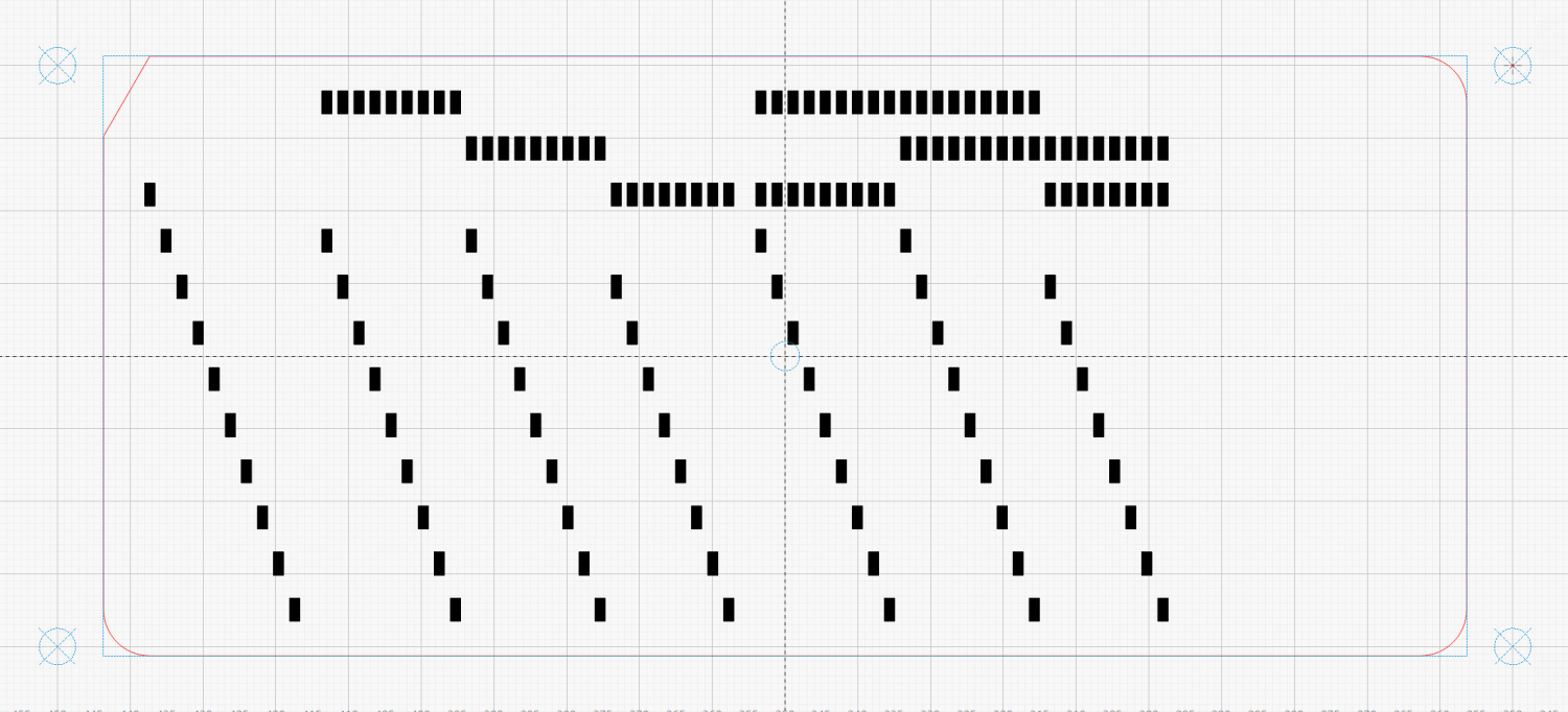
After considerable faffing, a few of the fifteen layers look like this in GIMP:
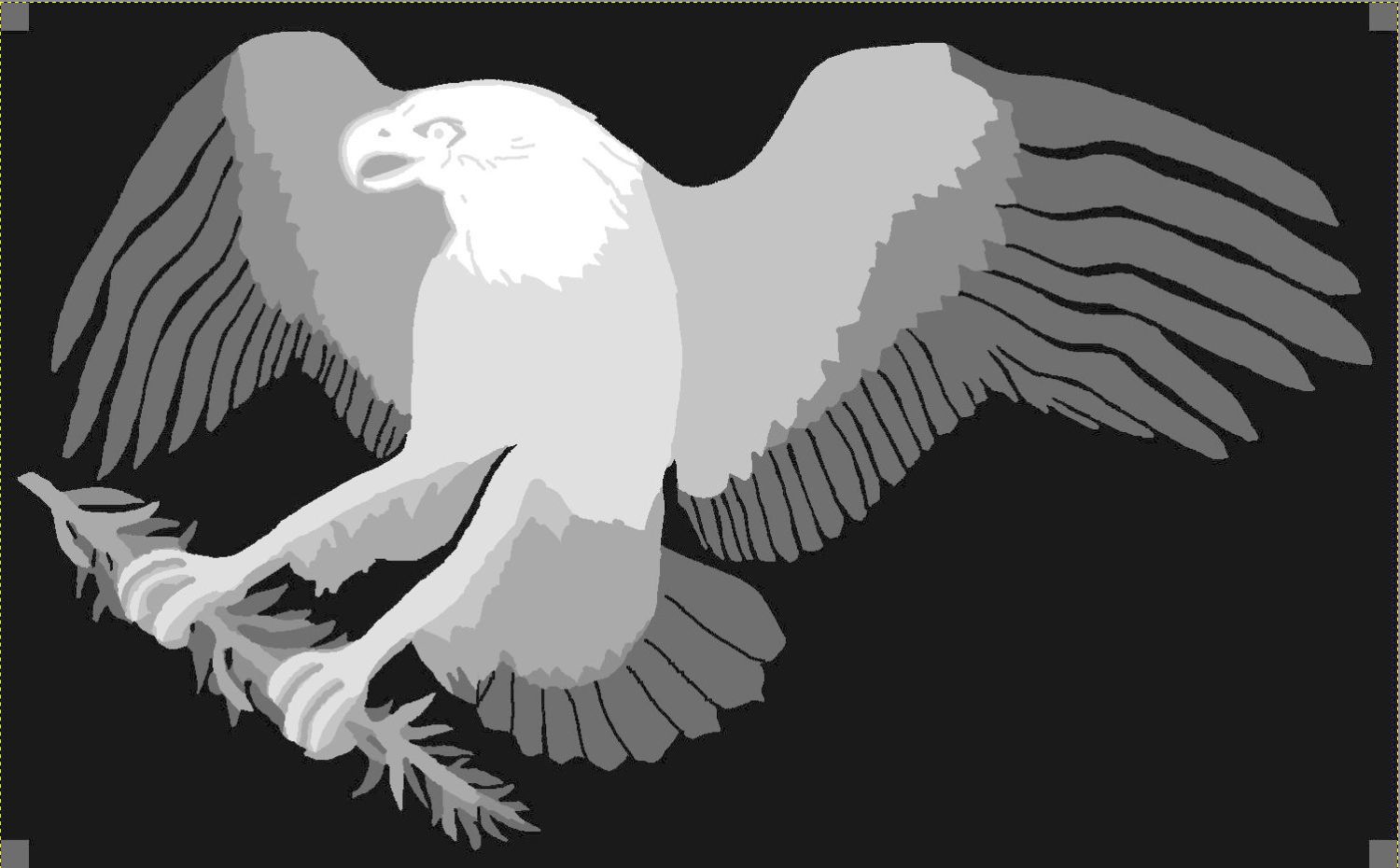
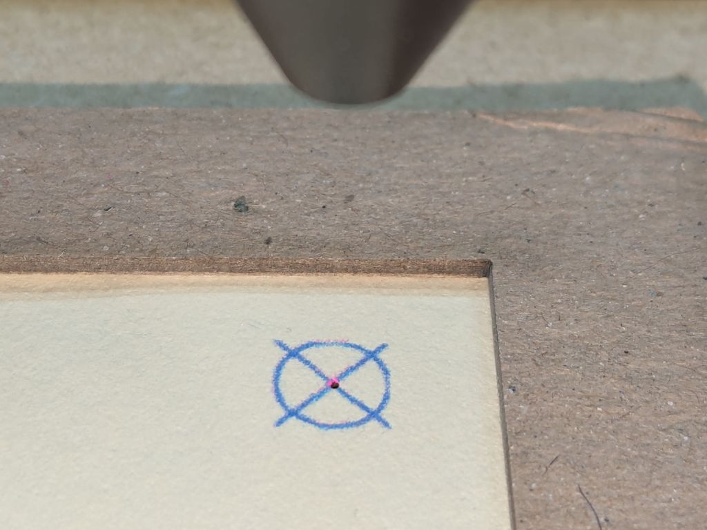
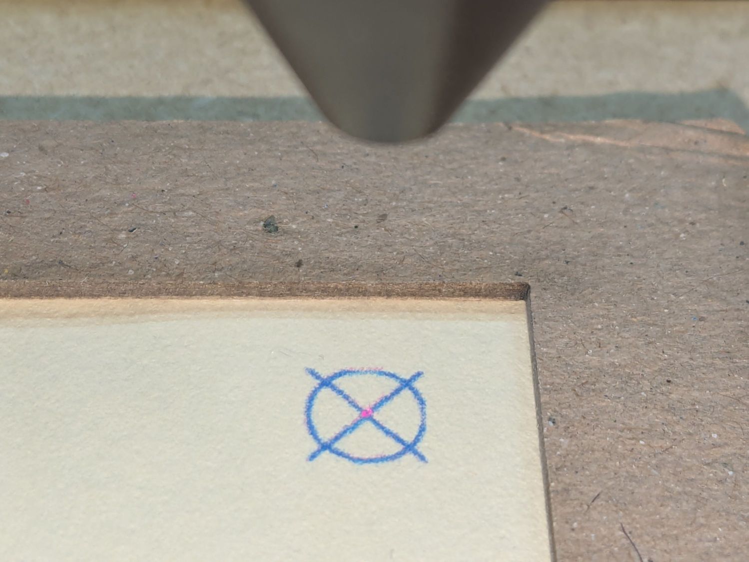
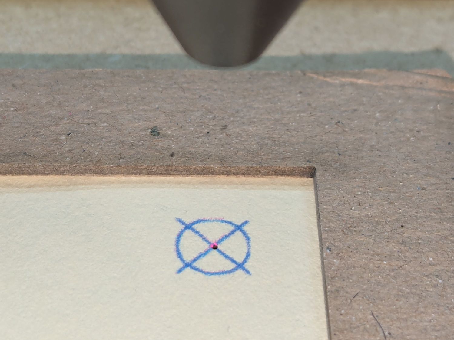
Each layer is a connected white region defining the cut perimeter, which will expose some part of the layer(s) below it in the stack. The small squares in the corners provide a bounding box to make all the layers snap to the same location.
Then:
- Select each layer’s shape + corner boxes with GIMP’s
Color Selecttool - Convert the selection to a path
- Export paths as SVG files (all fifteen of them!)
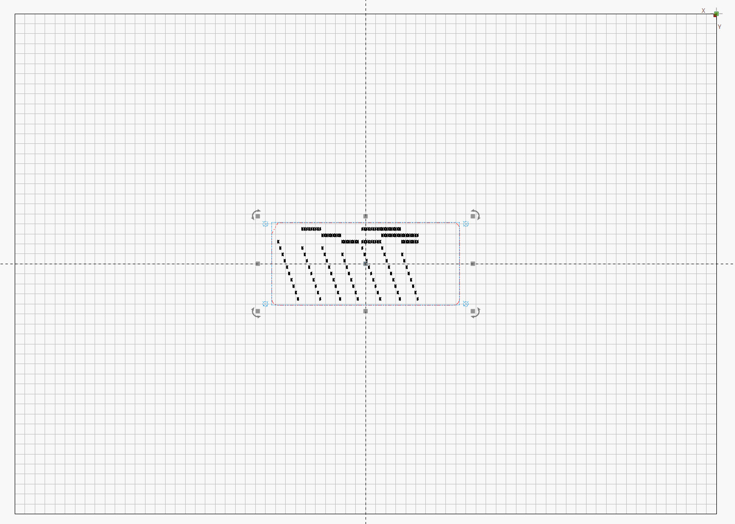
- Import SVGs into LightBurn & arrange neatly
- Put outlines on a cut layer, corner squares on a tool layer
- Burn each layer separately
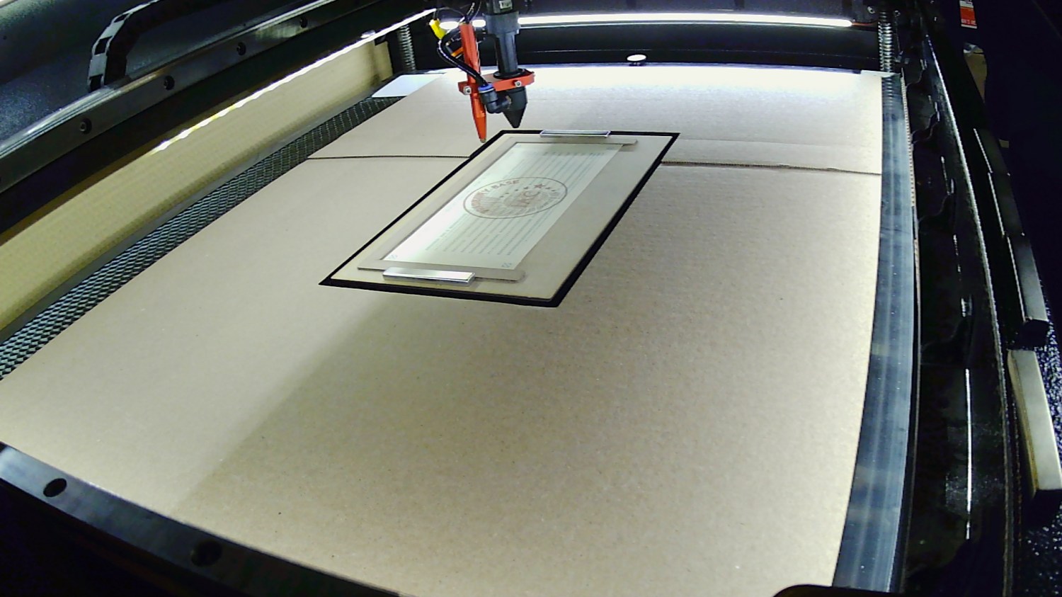
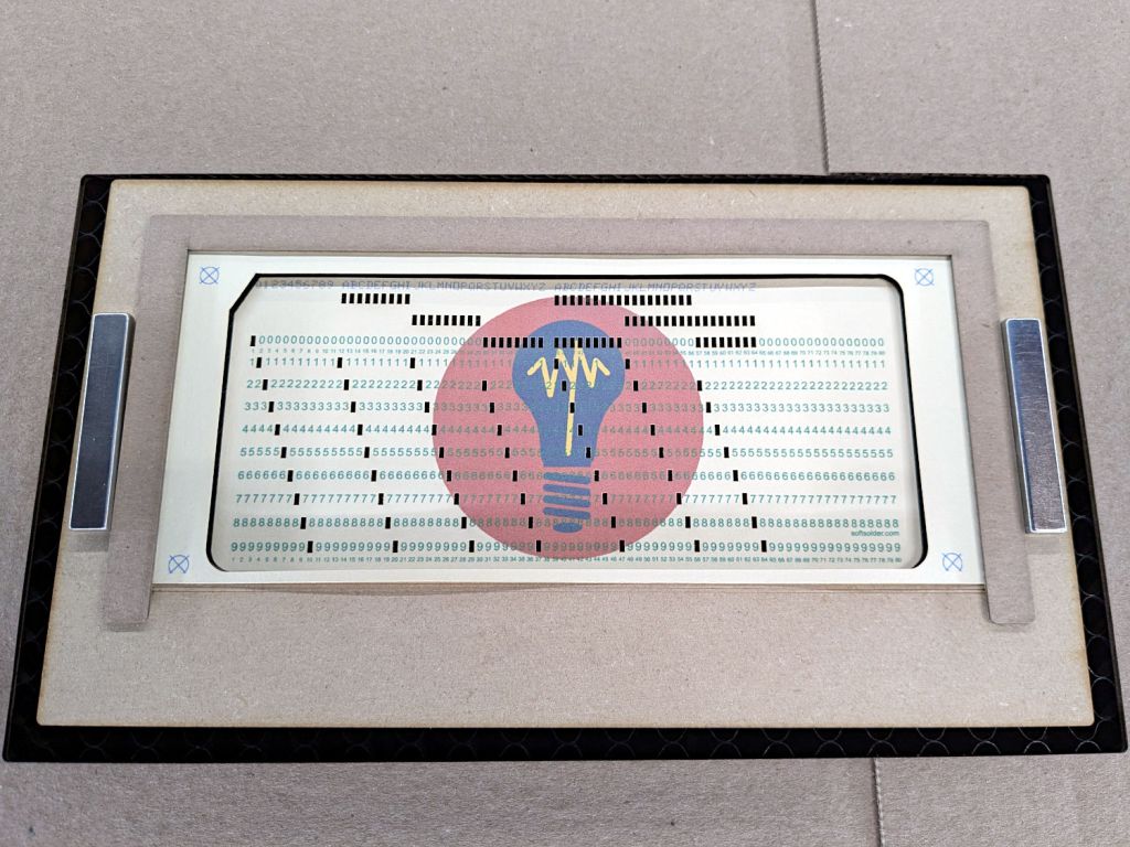
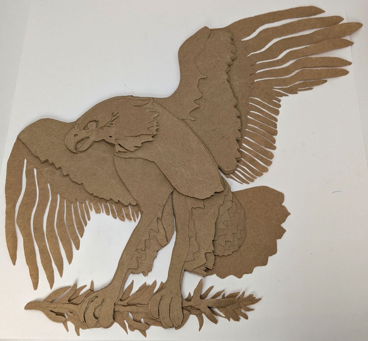
Testing the concept with packing paper looked surprisingly good:
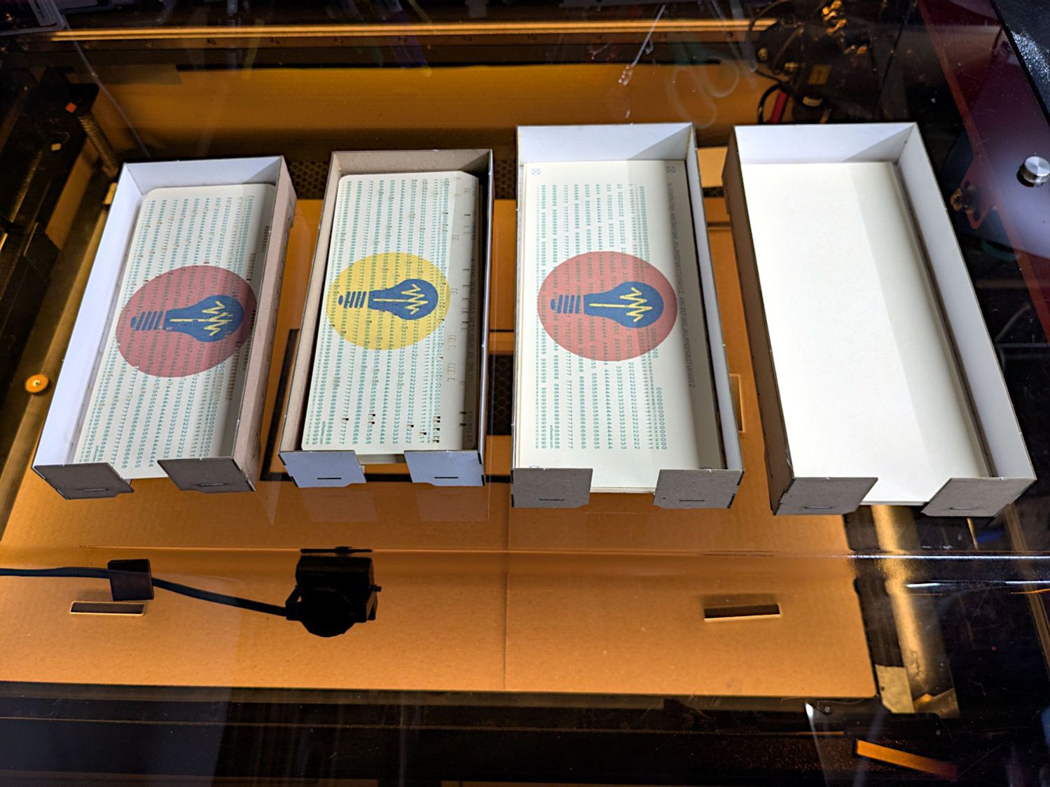
A few key layers on punched cards:
The changes for each of those iterations required tweaking the original layer images to eliminate obvious-in-retrospect problems, recreating the SVG files, and importing into LightBurn. This is a relentlessly manual process.
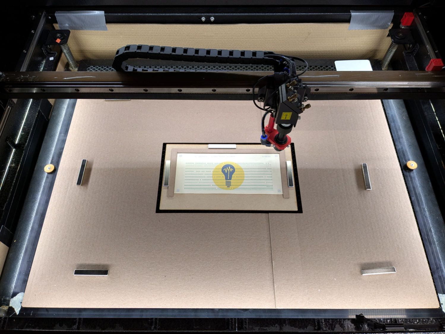
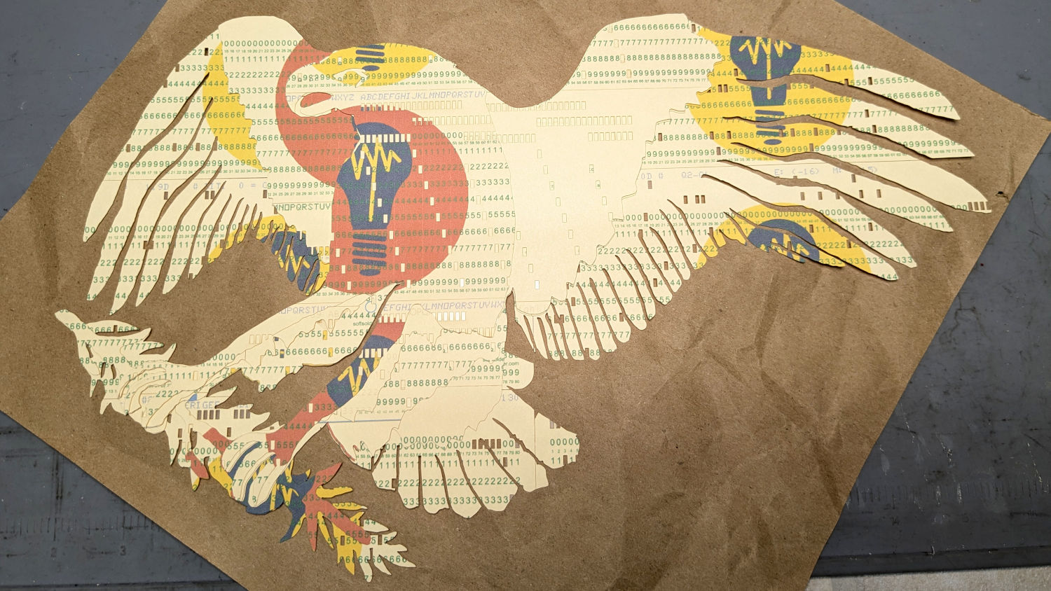
Then I ran a full-up test of all fifteen layers on cards punched with the Apollo source code.
Cutting the head layers from face-down cards made them sufficiently white, although it’d be nice to have a different beak color and darker eyes :
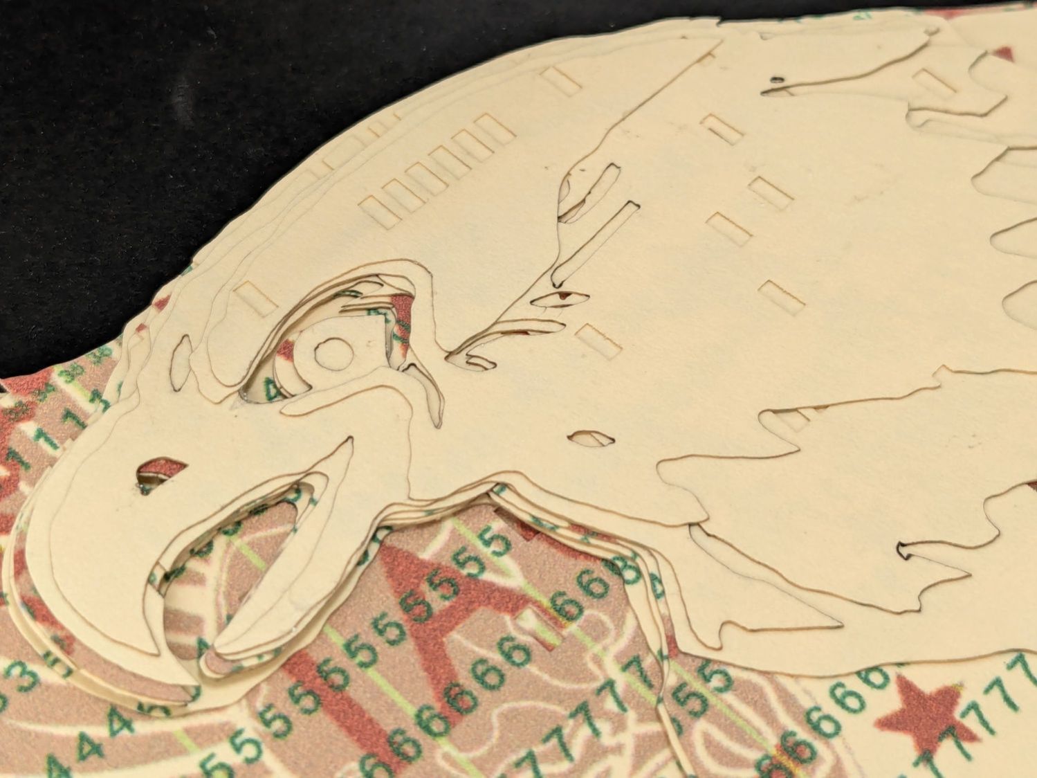
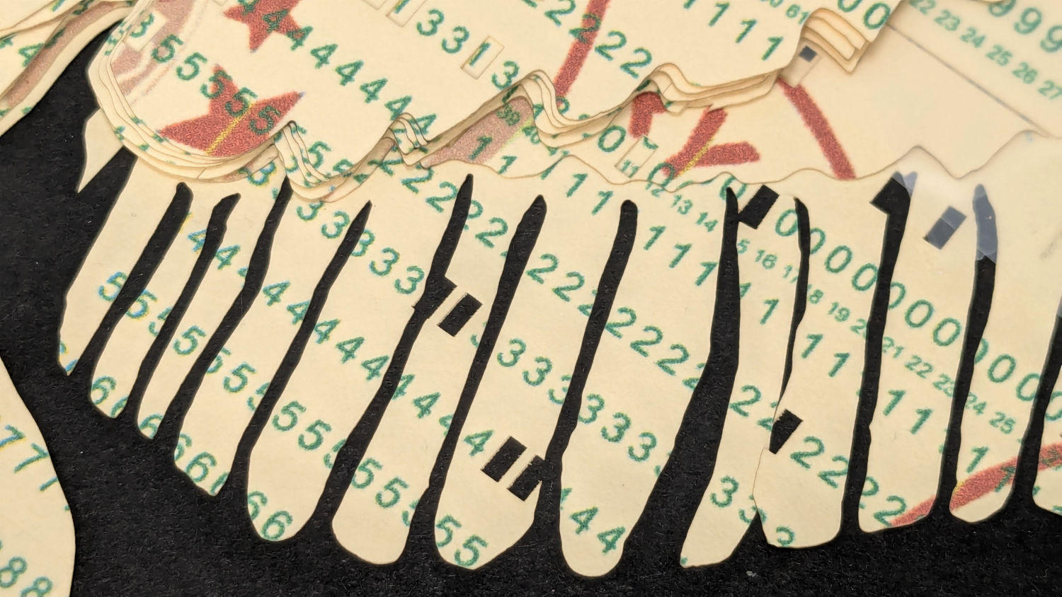
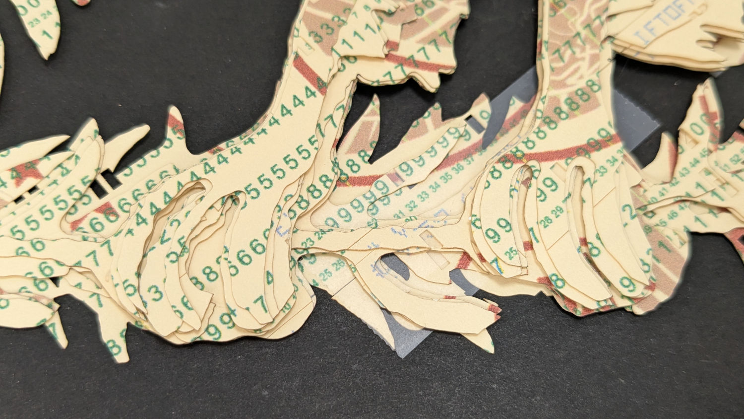
I must arrange the cards with text to put more holes in the wings, although too many will cause fragile feathers:
The white tail should be also done with face-down cards, more holes, and the three-way joint between the cards shifted under the tail layers to its left:
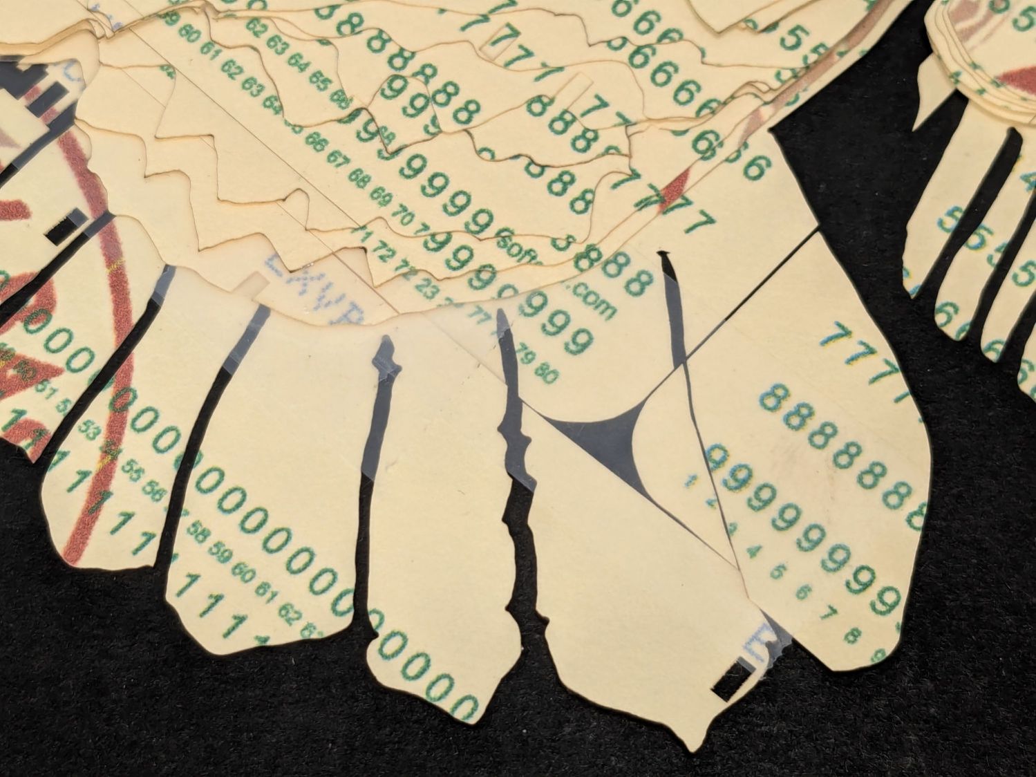
The feet and olive branch were a total faceplant, as successive layers did not register accurately enough to overlay the leaves:
Not to mention those ug-u-lee claws.
The wing layers need more rounding along their edges, perhaps with some thin cuts to emphasize the feathers.
On the whole, though, I think it turned out well.
Things to do:
- Registration holes / pins up to the top layer
- Remove speckles on all the layers
- Arrange cards for more hole density where needed
- Better glue application
- Different card colors?