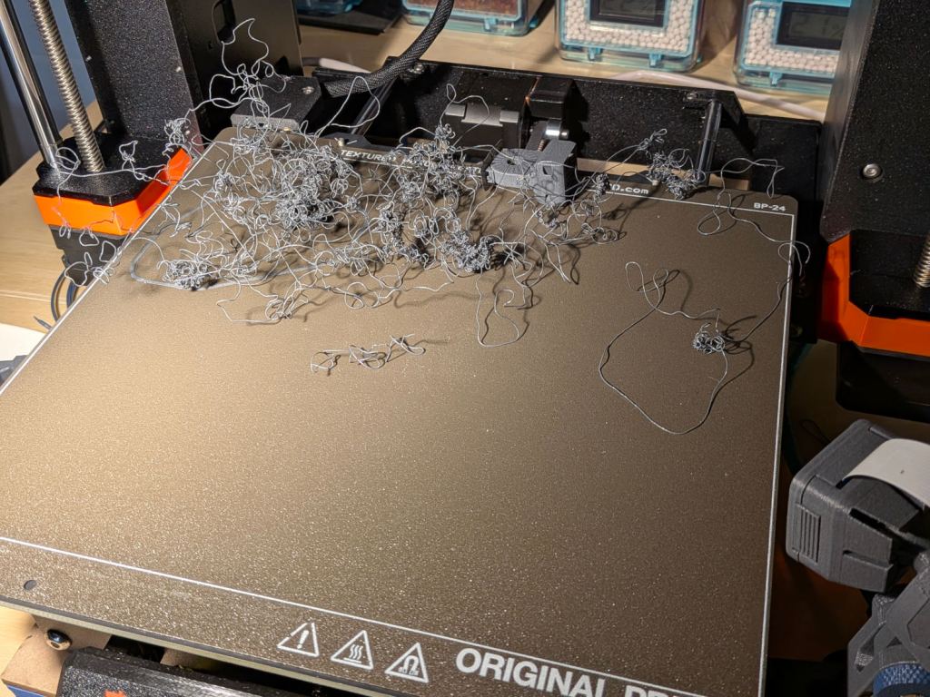
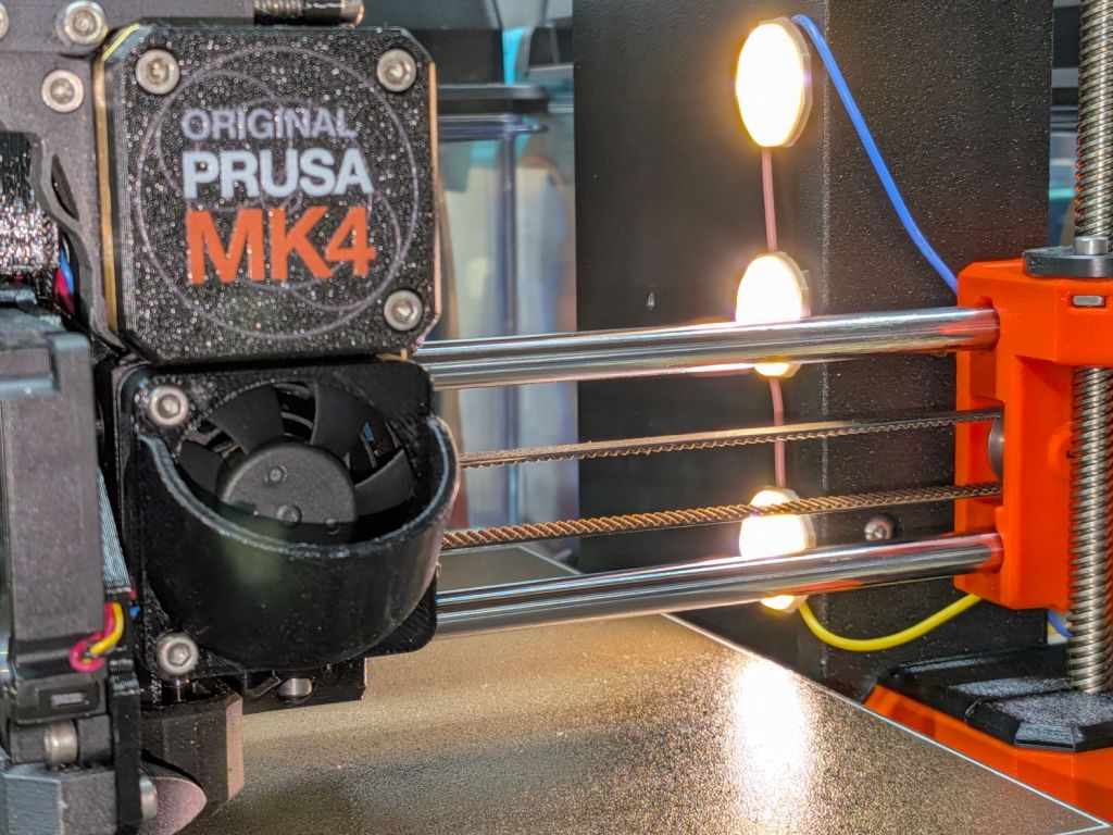
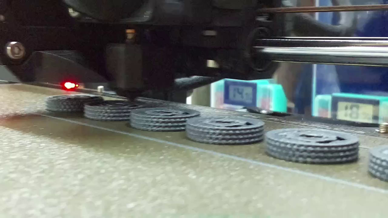
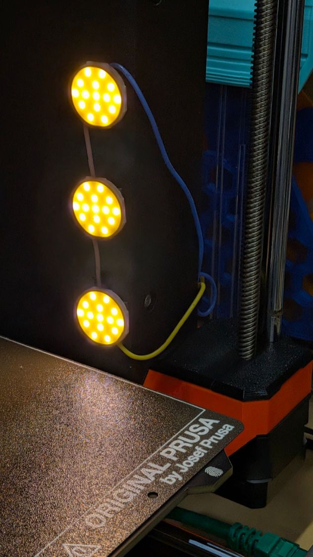
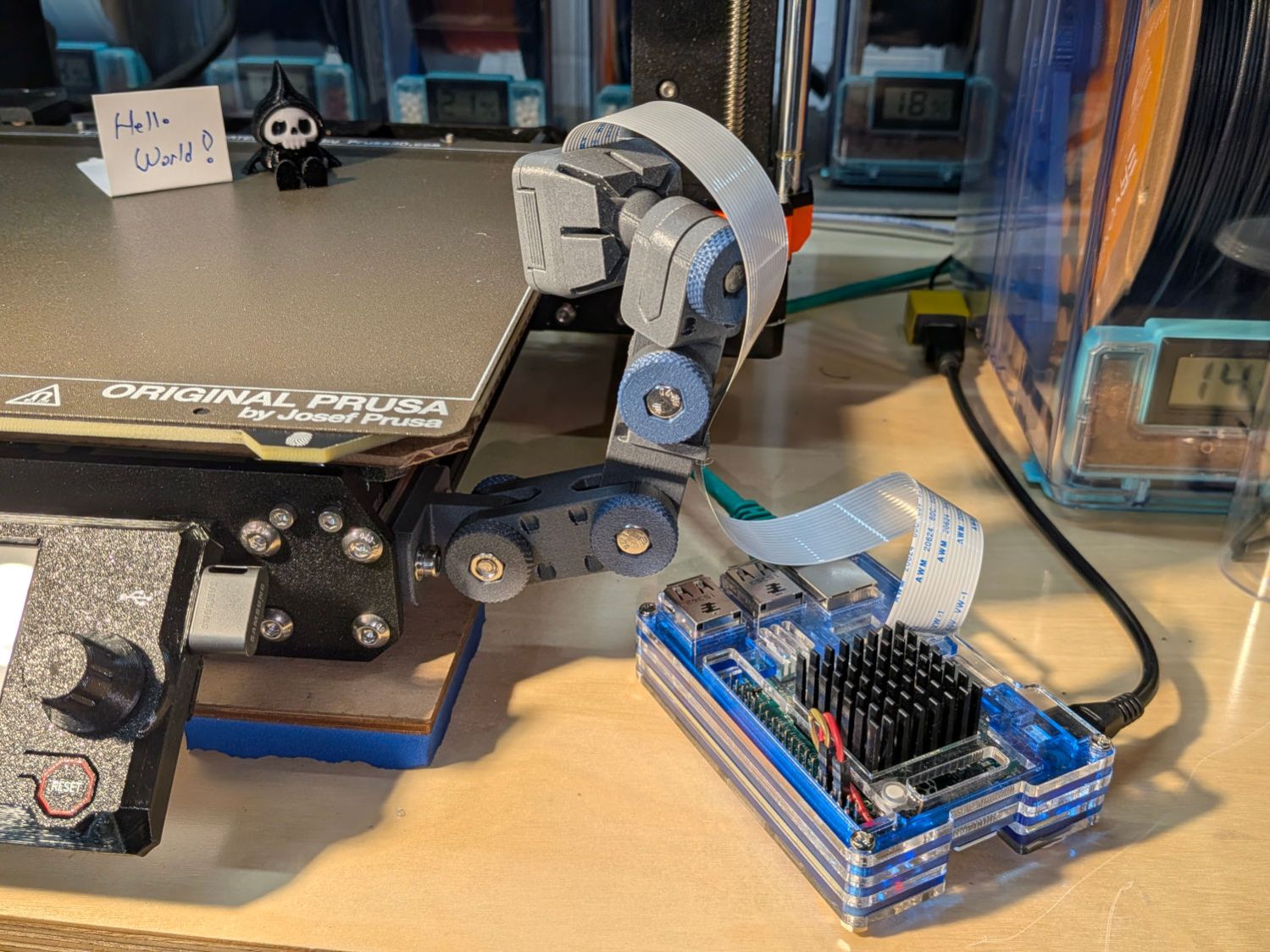
Having just set up the camera to watch the Prusa MK4’s platform, this situation caught my eye while sitting in the Comfy Chair at my desk:
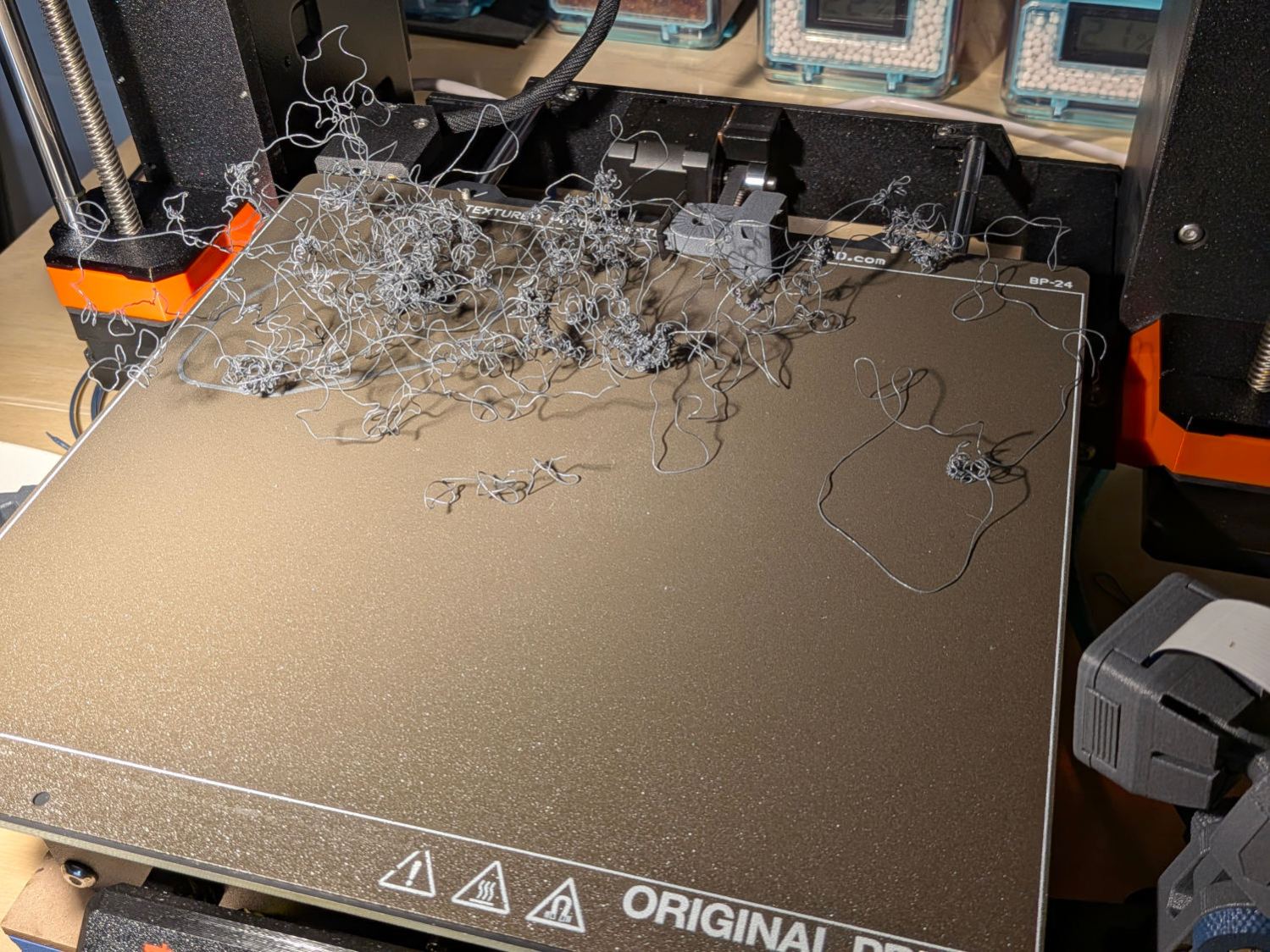
(The camera in the lower right doesn’t yet record videos, so you must imagine what I saw.) I forgot capturing this screenshot:
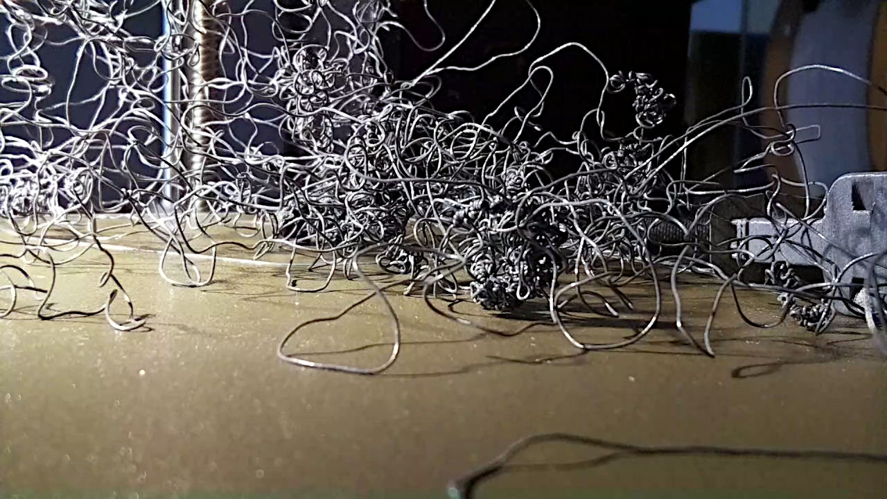
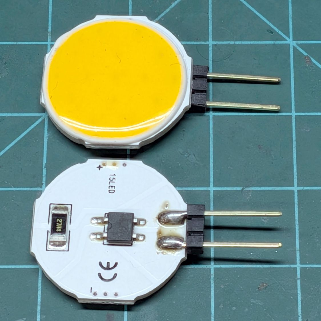
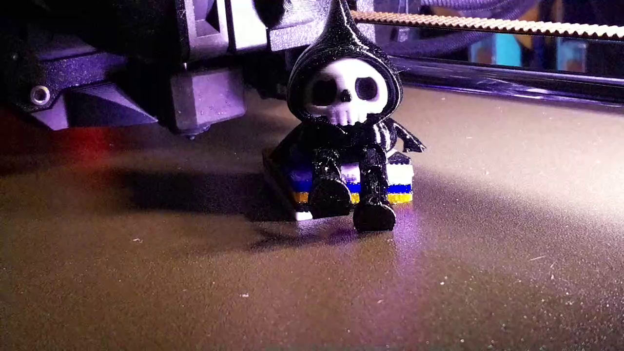
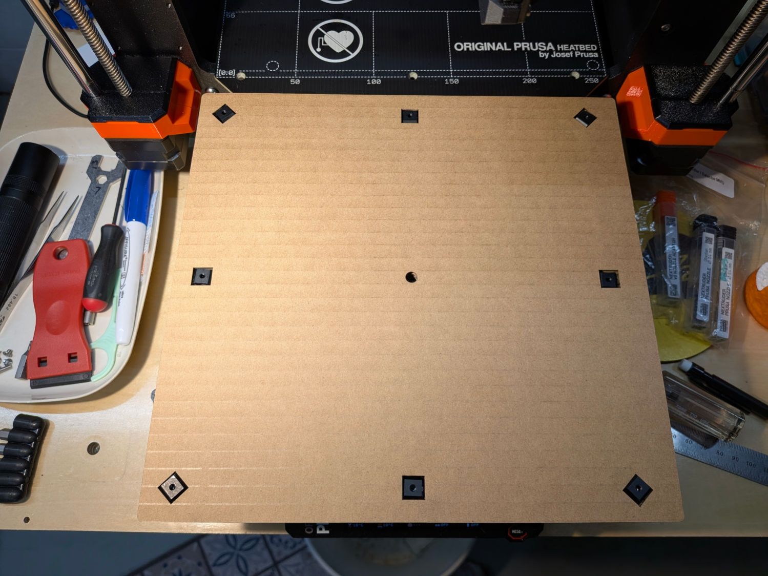
The nozzle was busily adding to the tangle, so I shut the printer off and trotted to the Basement Shop™ to find two more parts lying dead on the workbench:
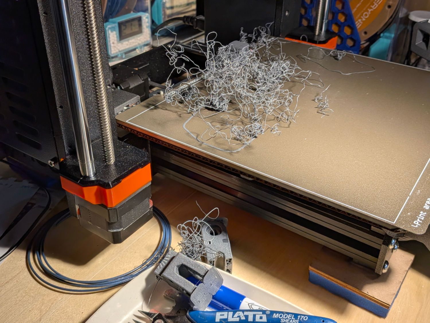
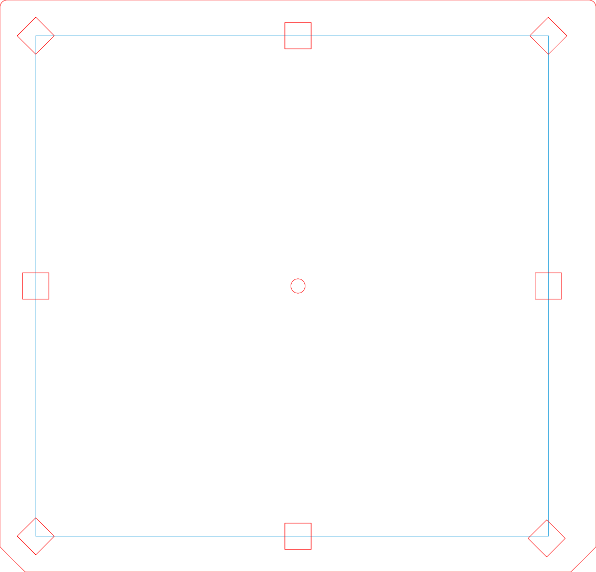
This was entirely my fault, as I’d ignored PrusaSlicer’s warning about inadequate adhesion for the camera mount link standing in the corner:
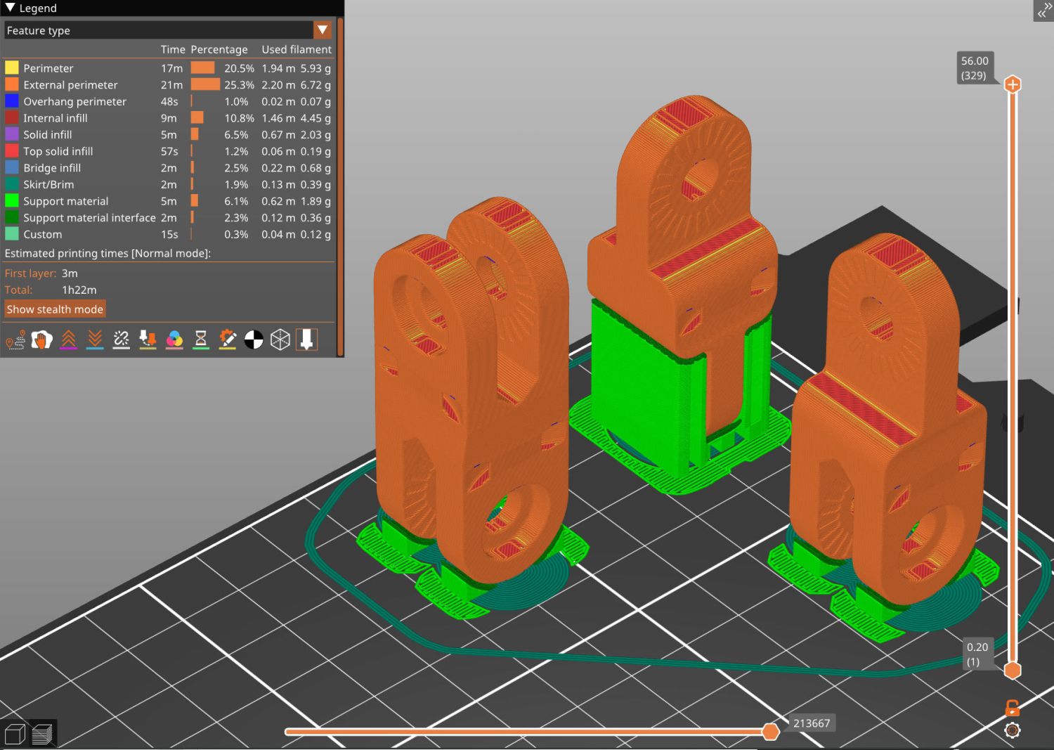
That’s the PrusaSlicer preview after adding a wider brim and painting more support structures on all three parts. Given larger footprints, the next attempt completed without drama, which is the normal outcome.
Moral of the story: Tall skinny parts need more surface area on the platform than you think, even with excellent adhesion.


