The Smell of Molten Projects in the Morning

Ed Nisley's Blog: Shop notes, electronics, firmware, machinery, 3D printing, laser cuttery, and curiosities. Contents: 100% human thinking, 0% AI slop.

Category: Machine Shop

Mechanical widgetry

  • Battery Organizer

    Battery Organizer

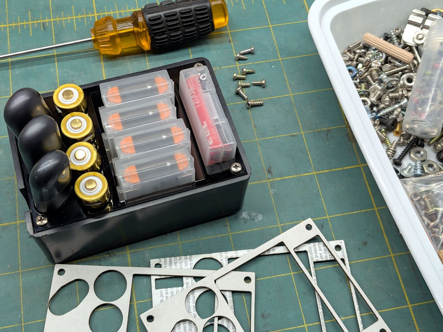
    A small box has been holding an assortment of batteries during their out-of-service phase and I finally made a lid to keep the contents from flopping around:

    Battery organizer
    Battery organizer

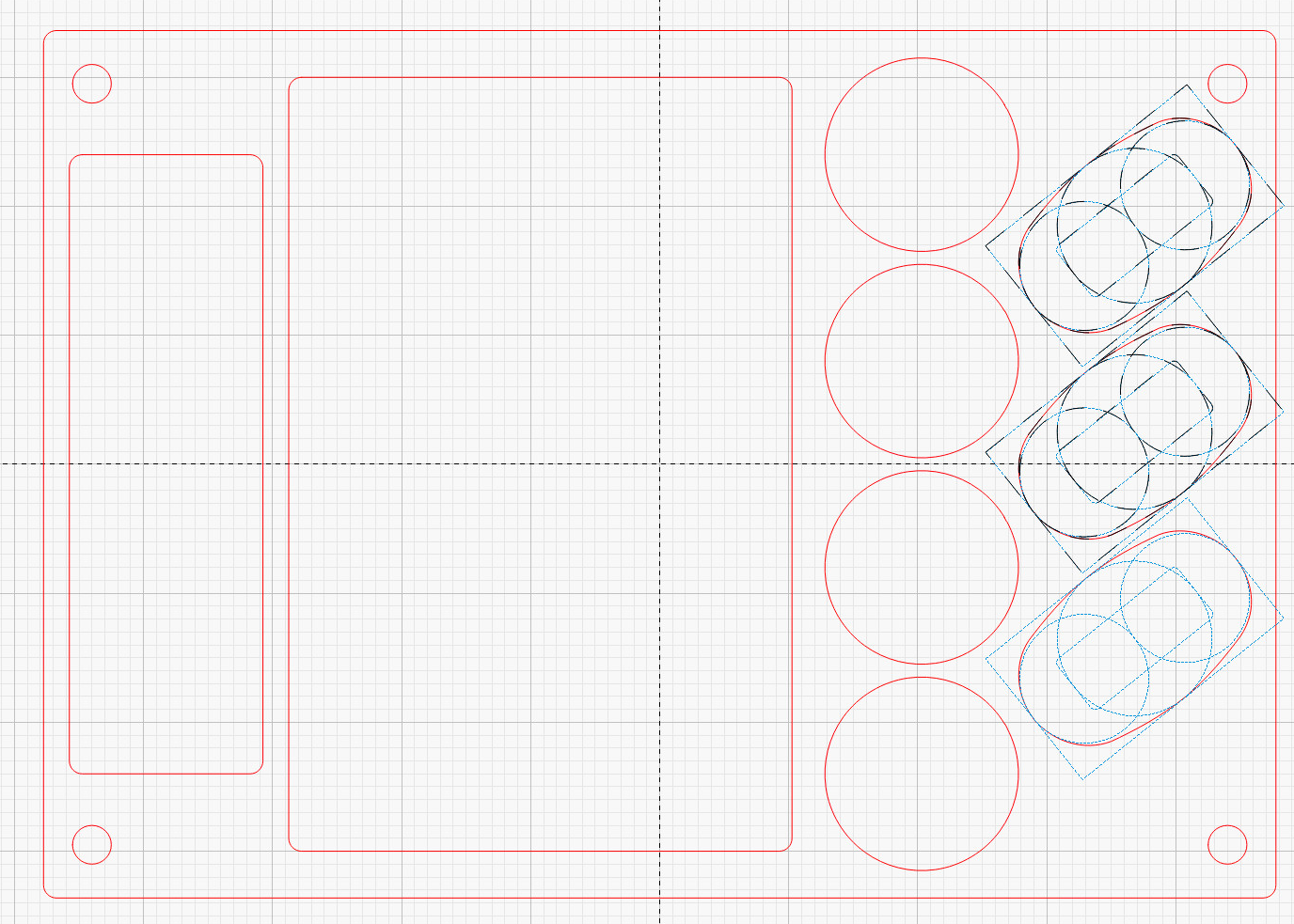
    The cardboard prototypes record the journey toward the black acrylic lid. The final LightBurn layout:

    Battery Collector - LightBurn layout
    Battery Collector – LightBurn layout

    For whatever it’s worth, the box holds:

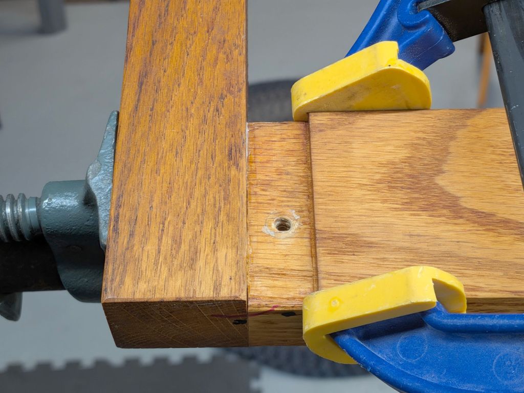
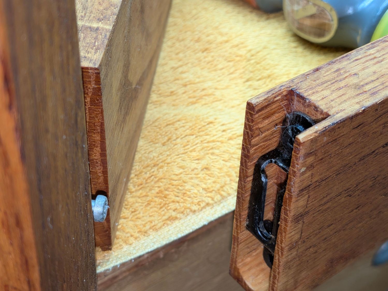
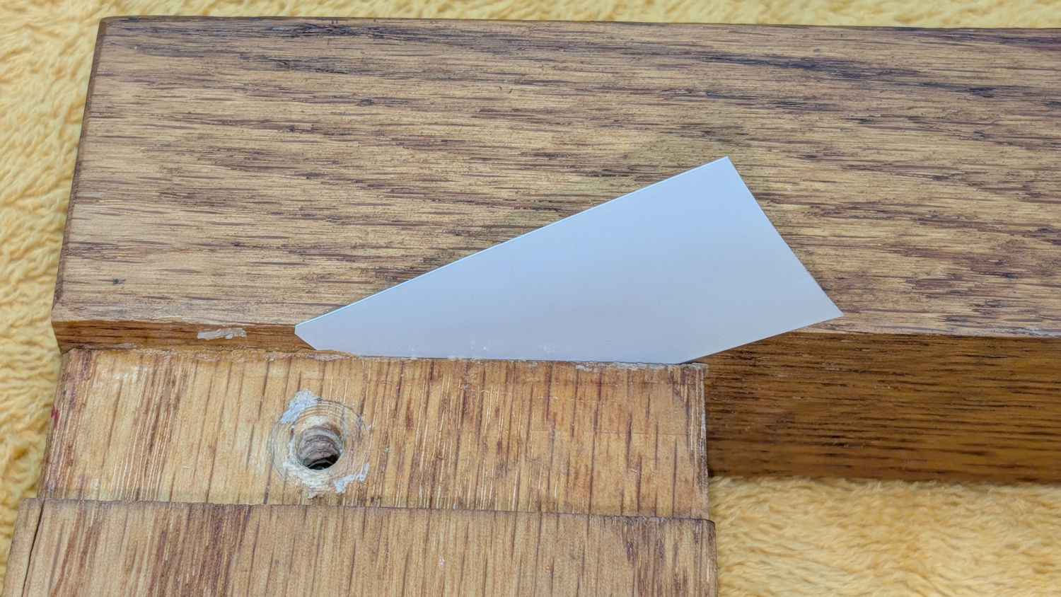
    The first four suitable & identical screws from the Tray o’ Tiny Screws hold the lid down. The ToTS contains screws and suchlike harvested from all the gadgetry headed for the recycling pile, making it a reliable source for any occasion.

  • Pressure-washed Stove Grates

    Pressure-washed Stove Grates

    Be it hereby declared: laying the absurdly heavy cast-iron grates from the stove on sawhorses in the driveway and pressure-washing them produces a dramatic improvement:

    Pressure-washed stove grates
    Pressure-washed stove grates

    They’re now devoid of the oil / grease / carbon accumulated during their decade of existence, little of which can be removed by hand; the shiny spots on the front right shrug off all solvents in my armory. The black finish still has plenty of scrapes & scuffs, but it’s no longer annoying.

    You might think Samsung stove grates would fit in a Samsung dishwasher, but they’re too big and too heavy.

    Also for the record: cyanoacrylate adhesive works wonderfully well to hold their little rubber feet in place.

  • Whirlpool Clothes Dryer: Thermal Cutoff Trip

    Whirlpool Clothes Dryer: Thermal Cutoff Trip

    A bit less than a year after replacing all the thermal switches / cutoffs / thermostats in the Whirlpool clothes dryer, the Thermal Cutoff went open-circuit. It’s located at the top of the heater duct:

    Whirlpool dryer - heater duct top
    Whirlpool dryer – heater duct top

    The wiring diagram lists it as tripping at 350 °F and “NOT RESETTABLE”:

    Whirlpool dryer - wiring diagram - detail
    Whirlpool dryer – wiring diagram – detail

    Curiously, the replacement switch had only one mark:

    Whirlpool Clothes Dryer - thermal cutoff - marking
    Whirlpool Clothes Dryer – thermal cutoff – marking

    I find it difficult to believe anybody would build a thermal cutout at 309°F = 154 °C.

    Crushing it with a Vise-Grip reveals the interior:

    Whirlpool Clothes Dryer - thermal cutoff - disassembled
    Whirlpool Clothes Dryer – thermal cutoff – disassembled

    I don’t know what permanently opens the circuit in there, but it definitely happened. The contacts remain unblemished, so they were pressed firmly together until the end.

    With nothing to lose, I reinstalled the Thermal Cutoff I removed last year (*) and the dryer works fine again.

    It is possible lint accumulating in the filter bag I added to the exhaust vent restricted the airflow enough to overheat the cutoff, but the Operating Thermostat should keep the air around 155 °F and the Hi Limit thermostat should have tripped at 250 °F, long before the temperature reached 350°F.

    Another cutoff will arrive shortly and will remain in the Box o’ Dryer Parts against future need.

    (*) Which is why I keep the old parts around, because a dubious part on hand is much better than the new part I might not be able to get due to, oh, “supply chain issues”.

  • Oak Stool Leg Creak

    Oak Stool Leg Creak

    Our square oak stool developed an annoying creak in two of its legs, resulting in a teardown & glue-up.

    The legs come in pairs held in place by snug screw fittings:

    Oak Stool Legs - mechanical joint
    Oak Stool Legs – mechanical joint

    The screw on the left slides into the tapered fitting on the right and latches firmly in place: no creaks in there! I have no idea what that fitting is called; my search-fu is unavailing.

    In any event, the offending legs were loose enough to admit a 6 mil = 0.16 mm miniblind snippet shim:

    Oak Stool Legs - loose joint
    Oak Stool Legs – loose joint

    Our Young Engineer, having taken up woodworking as a serious hobby, suggested the joint might have a loose dowel, which will be difficult to fix. Peering into the gap with a flashlight below showed that was the case:

    Oak Stool Legs - dowel revealed
    Oak Stool Legs – dowel revealed

    While it might be possible to force the joint apart enough to properly re-glue the dowels, I opted for a half measure by applying a spreader and easing wood glue into the gaps using the shim:

    Oak Stool Legs - gluing
    Oak Stool Legs – gluing

    An overnight session with the pipe clamp eliminated the creak, at least for now:

    Oak Stool Legs - clamping
    Oak Stool Legs – clamping

    The blue-and-yellow clamp fixed the loose splinter you didn’t notice in the second picture.

    Traces of glue along inside the joints suggest I’d done something like in the deep past. Ideally, I’ve learned enough to get it right this time.

  • Steel Shelving Foot Pads

    Steel Shelving Foot Pads

    All of the plastic pads vanished from the legs of a steel shelf unit somewhere along the way:

    Steel Shelving Foot Pads - post shape
    Steel Shelving Foot Pads – post shape

    Some solid modeling produced a suitable replacement shape:

    Steel Shelving Foot Pads - no pegs - solid model
    Steel Shelving Foot Pads – no pegs – solid model

    A few prototypes (with a broken OEM version at lower left) matched the model to reality:

    Steel Shelving Foot Pads - test pieces
    Steel Shelving Foot Pads – test pieces

    They’re natural & black TPU, because the job requirements include being tough and bendy:

    Steel Shelving Foot Pads - installed
    Steel Shelving Foot Pads – installed

    Each one takes about half an hour to ooze from the Makergear M2, so after verifying the prototype’s fit, printing four at a time makes sense:

    Steel Shelving Foot Pads - slicer
    Steel Shelving Foot Pads – slicer

    The OpenSCAD code includes the pegs in the original and the first chunky TPU version:

    Steel Shelving Foot Pads - with pegs - solid model
    Steel Shelving Foot Pads – with pegs – solid model

    It turns out they don’t have any obvious benefit in a TPU pad, so they’re disabled in the code.

    Now those legs sit firmly on the floor and the post tops aren’t nearly so threatening.

    The OpenSCAD source code as a GitHub Gist:

    // Steel Shelf Foot Pads
    // Ed Nisley – KE4ZNU
    // 2026-04-18
    include <BOSL2/std.scad>
    /* [Hidden] */
    Protrusion = 0.01;
    NumSides = 4*9;
    $fn=NumSides;
    Clearance = 1.0/2;
    WallThick = 1.0 + Clearance;
    BaseThick = 2.0;
    PadOAH = BaseThick + 11.0;
    RollID = 6.4;
    RollOD = 7.4 + Clearance;
    RollOffset = 29.5;
    LegThick = 0.5 + 2*Clearance;
    Pins = [
    [-(RollOD/2), (RollOffset + RollOD/2),0],
    [(RollOffset + RollOD/2), -(RollOD/2),0],
    ];
    //—–
    // Build things
    union() {
    difference() {
    union() {
    for (pin = Pins)
    translate(pin)
    cyl(PadOAH,d=RollOD + 2*WallThick,anchor=BOTTOM);
    translate([-(WallThick + LegThick),-(WallThick + LegThick),0])
    cuboid([2*WallThick + LegThick,WallThick + LegThick + Pins[0].y,PadOAH],
    anchor=BOTTOM+LEFT+FRONT);
    translate([-(WallThick + LegThick),-(WallThick + LegThick),0])
    cuboid([WallThick + LegThick + Pins[1].x,2*WallThick + LegThick,PadOAH],
    anchor=BOTTOM+LEFT+FRONT);
    cyl(PadOAH,r=(WallThick + LegThick),anchor=BOTTOM);
    }
    up(BaseThick)
    cyl(PadOAH,r=LegThick,anchor=BOTTOM);
    up(BaseThick)
    for (pin = Pins)
    translate(pin)
    cyl(PadOAH,d=RollOD,anchor=BOTTOM);
    up(BaseThick) {
    translate(Pins[0])
    cuboid([RollOD/2,RollOD/2,PadOAH],anchor=BOTTOM+LEFT+BACK);
    translate(Pins[1])
    cuboid([RollOD/2,RollOD/2,PadOAH],anchor=BOTTOM+RIGHT+FRONT);
    }
    up(BaseThick) {
    fwd(LegThick)
    cuboid([LegThick,Pins[0].y + LegThick,PadOAH],anchor=BOTTOM+RIGHT+FRONT);
    left(LegThick)
    cuboid([Pins[1].x + LegThick,LegThick,PadOAH],anchor=BOTTOM+LEFT+BACK);
    }
    }
    if (false)
    for (pin = Pins)
    translate(pin) {
    cyl(PadOAH,d=RollID/2,anchor=BOTTOM);
    for (a = [0,90])
    zrot(a)
    cuboid([1.0,RollID – 2*Clearance,PadOAH],anchor=BOTTOM);
    }
    }

  • PolyDryer Humidity: April-ish

    PolyDryer Humidity: April-ish

    After about five weeks:

    2026-04-16
    Filament%RHWeight – gWt gain – gGain %
    PETG White14
    PETG Black14
    PETG Orange2252.52.55.0%
    PETG Natural15
    PETG-CF Blue2355.45.410.8%
    PETG-CF Gray18
    PETG-CF Black14
    PETG Blue10
    TPU Clear14
    TPU Black14

    Most of the PolyDryer boxes had the same humidity as before, so I didn’t disturb them. When the humidity starts to rise, then we’ll see what’s going on in there.

    The PETG Orange meter continues to misbehave and has been glitching from 22% to 30%. The indicator card shows the humidity is around 10% inside and the relatively low weight gain suggests there’s not much water to be adsorbed.

    The PETG-CF Blue spool is new and, once again, shows filament does not arrive bone-dry in the factory wrapper.

    Those two boxes now have alumina beads.

    Dehydrating the jar of wet silica gel on the induction cooktop (set for 405 °F) sweated it down from 532 g to 503 g over the course of four hours, with nearly all of that change in the first two hours.

    Obligatory photo from a while ago, because it looks pretty much the same now:

    Silica gel beads - drying
    Silica gel beads – drying
  • Image Trace and Cut

    Image Trace and Cut

    Having admired the paper craft at RavensBlight and with some experience in simple paper cuttery, I had to try my hand at the Ghost Truck. Rather than using an X-Acto knife and straight edge around the perimeter, I set it up for laser cutting.

    The instructions & layouts are images in PDF files, so it’s straightforward to import them into LightBurn and trace the outlines:

    Ghost Truck - LightBurn vectors
    Ghost Truck – LightBurn vectors

    Tracing produces short vectors and irregular curves:

    Ghost Truck - LightBurn pre-optimize
    Ghost Truck – LightBurn pre-optimize

    The Optimize Shapes tool and a little manual intervention clean things up:

    Ghost Truck - LightBurn post-optimize
    Ghost Truck – LightBurn post-optimize

    You must manually add any cuts buried in the pattern, as in the Trailer Wheels parts shown above, so pay attention to the instructions.

    Use the Move Laser tool to put the laser head at an obvious point on the layout, then skootch the printed page (in a Letter size fixture) to put that point under the beam. Repeat for another point, iterate until satisfied, then Fire The Laser:

    Ghost Truck - cutout overview
    Ghost Truck – cutout overview

    Some irregularities peek around the edges:

    Ghost Truck - cutout detail
    Ghost Truck – cutout detail

    On the whole, it’s much better than I could do with a knife.

    Repeat for the other seven pages of parts:

    Ghost Truck - Assembly
    Ghost Truck – Assembly

    With some diligence I may have it ready for All Hallows Eve …