Ruida laser controllers do not allow the platform to rise above the U=0 origin set by the autofocus pen = switch. While this isn’t a problem for flat surfaces, focusing on the exact top of a horizontal cylinder, particularly a small rod, may be overly difficult.
So a focusing pad seems like a Good Idea™:
The general idea:
- Align a flat horizontal surface with the rotary chuck’s axis
- Do the autofocus operation with a well-defined landing zone under the pen
- The
Focus Distanceputs the laser head at the proper height for a focused spot on the pad - Jogging the head upward (= platform downward) by the workpiece radius puts the focused spot exactly at the right height
- Remove the focus pad
- Install the workpiece
- Fire The Laser
The solid model:

Features of note:
- The chuck jaws fit into the recesses on the left end for a firm grip with good alignment
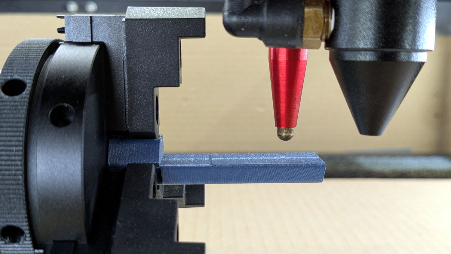
- The lengthwise notch lies on the rotary axis parallel to the laser’s X axis
- The crosswise notch is juuust rightward of the chuck jaws, marking the leftmost end of whatever you’re engraving
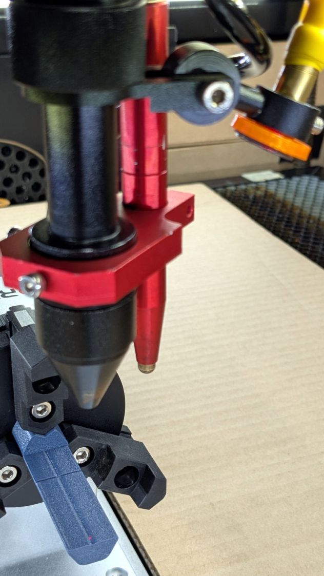
Because I added a home switch to the Ortur YRC-1 case, Jaw 1 automagically ends up on top after homing, thus automagically making the focus pad horizontal. Getting that right required fine-tuning the rotary’s home switch trip point, which turned out to be easier to do using the Home Offset configuration value after I replaced the cam I thought would work:
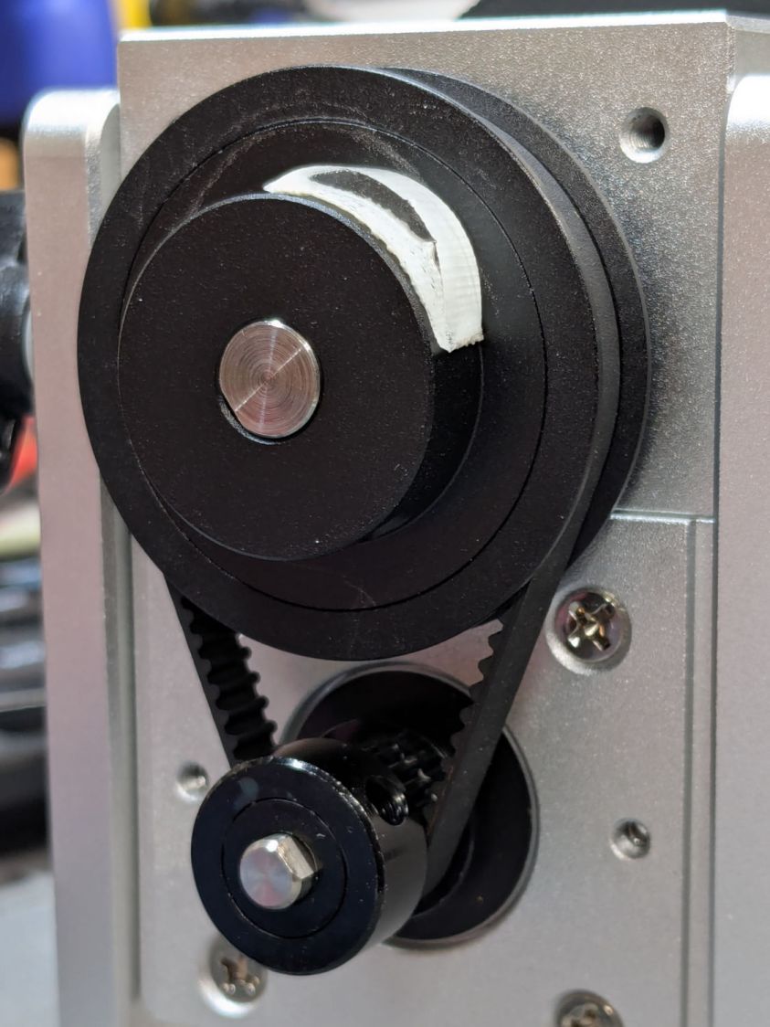
Instead, a simple M4 setscrew (standing proud of the pulley surface in one of the tapped holes for the real setscrew securing the pulley to the shaft) trips the switch much more repeatably :
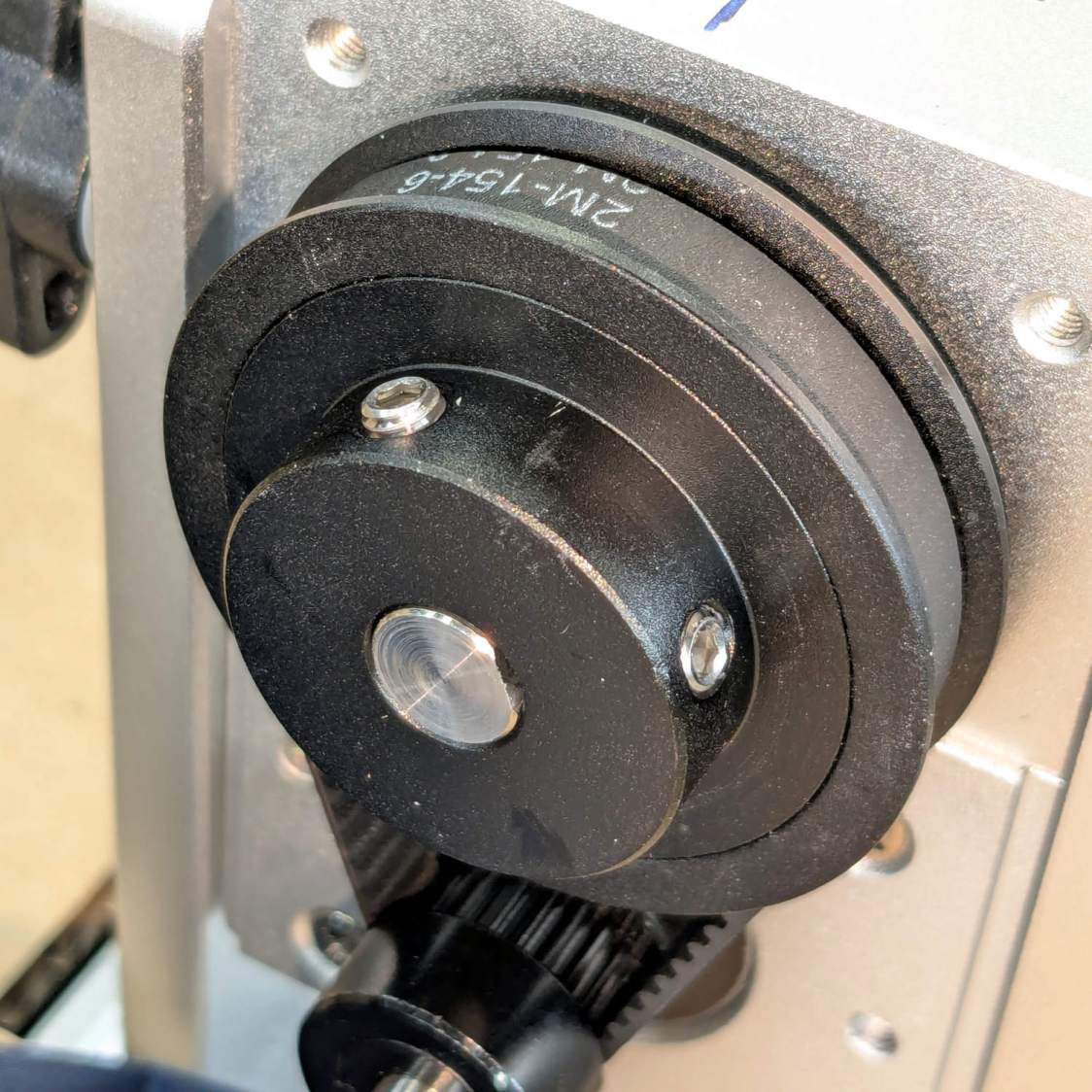
The setscrew on the right sits flush with the surface to prevent the switch roller from falling into the hole. The real setscrew underneath it locks the pulley to the shaft’s flat.
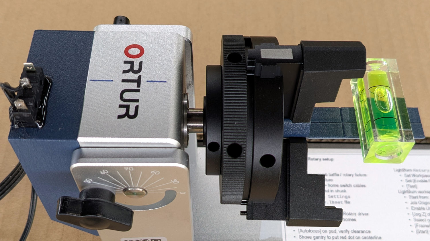
With that in place, a quick binary search settled on a Y axis Home Offset = 1.75 mm to put the pad level with the top of the rotary’s case, which is Level Enough™ due to my tweaking the machine’s foot elevations after jacking the whole machine up on risers:
The Home Offset value:
The speed and acceleration values are much lower than used with the linear Y axis, because apparently Ruida computes the corresponding step values using the workpiece diameter in the Rotary section. Small diameters produce impossibly fast motions, which suggests they expect you to set the optimum values based on back-calculations from the object diameter; ain’t nobody got time for that.
Anyhow.
After autofocusing, the red-dot pointer now indicates the laser spot position, so jog the X axis and drag the gantry to put the spot on the axis mark:
The orange rim on the red-dot pointer cuts down the beam intensity to make a smaller dot and provides easier position tweaks.
Then jog the X axis to put the dot at the transverse mark just beyond the chuck jaws:
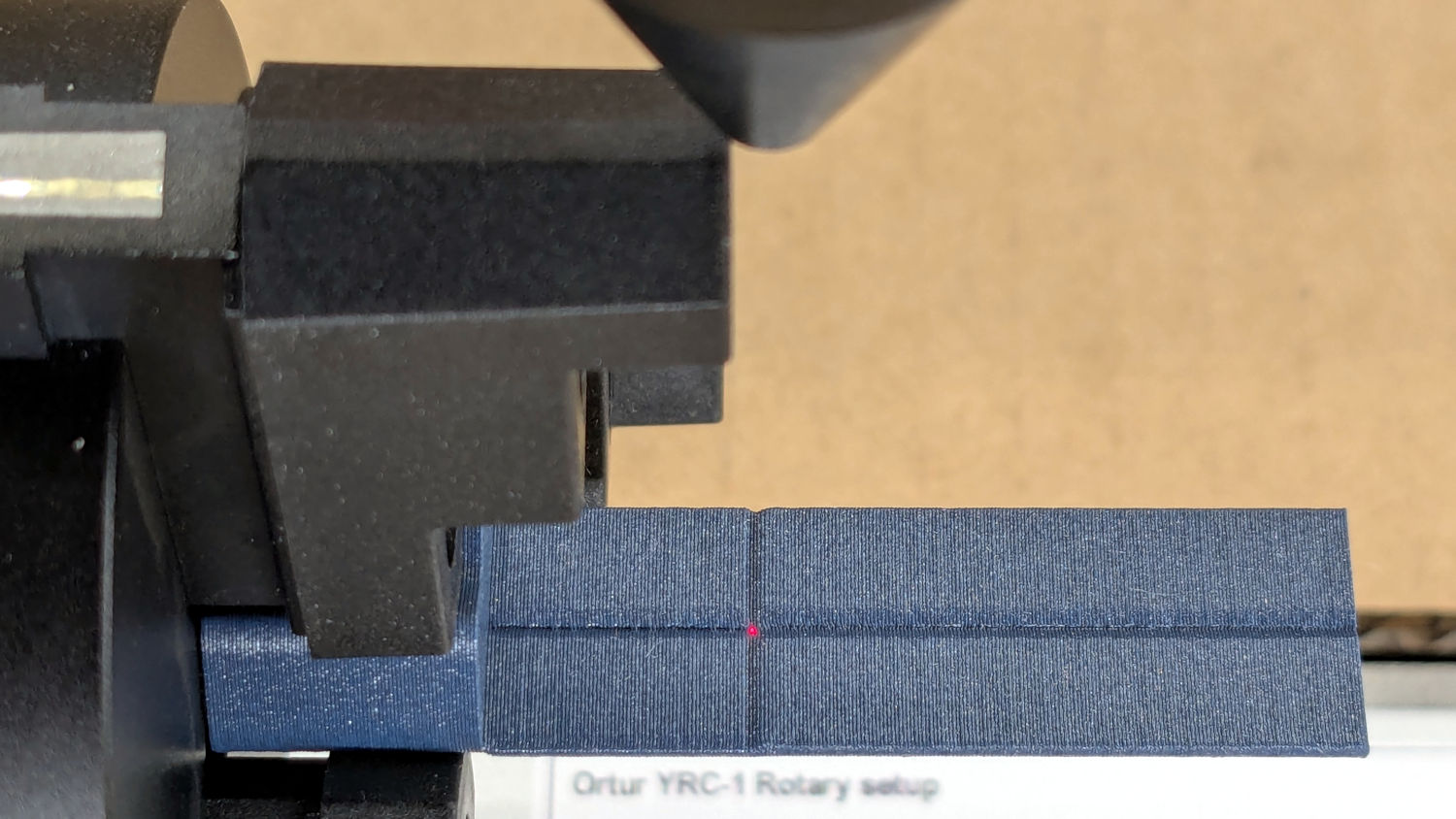
Hit the Ruida Origin button to set that as the user origin, so you can reference the LightBurn design to the hardware position.
Move the platform down by the workpiece radius, jog the nozzle along the X axis to get it out of the way, remove the focus pad, install the workpiece, and you’re good to go. The checklist visible beyond the bubble level shows it’s not quite that simple, but we’re getting there.
The OpenSCAD source code as a GitHub Gist:
| // Ortur Rotary Focus Pad | |
| // Ed Nisley – KE4ZNU | |
| // 2026-01-04 | |
| include <BOSL2/std.scad> | |
| Style = "Show"; // [Build,Show] | |
| /* [Hidden] */ | |
| ID = 0; | |
| OD = 1; | |
| LENGTH = 2; | |
| HoleWindage = 0.2; | |
| Protrusion = 0.1; | |
| NumSides = 8*3*4; | |
| $fn=NumSides; | |
| // Magic numbers to fit Ortur jaws | |
| PadOAL = 60.0; // clear assist air fitting | |
| PadIR = 7.0; // jaw tip 35 mm above this point | |
| JawOAL = 14.0; // clear large jaws | |
| Reticle = [0.7,0.7,PadOAL]; | |
| OriginOffset = 28.0; // X origin from chuck plate | |
| //—– | |
| // Pad to give autofocus probe a flat landing zone | |
| module FocusPad() { | |
| difference() { | |
| linear_extrude(PadOAL) | |
| hexagon(ir=PadIR,realign=true,rounding=3.0); | |
| up(JawOAL) { | |
| cube(PadOAL,anchor=BOTTOM+LEFT); | |
| cube(Reticle,spin=45,anchor=BOTTOM); | |
| } | |
| up(OriginOffset) | |
| cube(Reticle,spin=45,orient=FRONT,anchor=CENTER); | |
| for (a=[0:120:360]) | |
| rotate(a) | |
| down(Protrusion) | |
| linear_extrude(JawOAL + 2*Protrusion) | |
| right(PadIR + 15 – 2) // eyeball fit | |
| hexagon(or=15,rounding=0.5); | |
| } | |
| } | |
| //—– | |
| // Build things | |
| if (Style == "Show") | |
| yrot(90) | |
| zrot(180) | |
| FocusPad(); | |
| if (Style == "Build") | |
| FocusPad(); | |

Comments
5 responses to “Ortur YRC-1: Autofocus Pad”
Ed,
I can see you are quite skilled with OpenScad and it’s probably intuitive by now, but have you thought about using OnShape, which is free and perfect for 3d printing. I’ve beenusing it for 6 years now and although I also have a subscription (pricey) to Creo wirth their CNC Cam package, I do almost all of my 3d printing design with OnShape. Cost if it is one is all of my desings wind up publically accessible, but that’s limited to other users and has never beena problem.
I can often whip up a design and be printing in 20 minutes. work done this way tends to be iterative because cost of print is mostly time, and I canoften get a better idea of how to complete the thing once I’m holding it in my hand
and thanks for continuing topublish all of your schemes, well I assum it is all of them, Isn’t it?
John F
OnShape and its ilk solve a myriad problems I don’t have, plus locking designs in a proprietary coffin. :grin:
Nearly every object I need looks like a bracket and I’m (obviously) a big fan of parametric designs, so using a few known measurements to slam geometric shapes together makes more sense to me than trying to draw a thing, then redrawing it when a measurement changes. Being able to tweak the spacing by a millimeter, have the thing rearrange itself around the new holes, and get a new thing just like the old thing (only a little different) without fiddling about is wonderful.
Suffice it to say you see most of my designs here. :evil_grin:
At some point I should describe discovering my aphantasia with a score of zero on the VVIQ. In short, at long last I know why I prefer a text-based “drawing” program.
If I had to do what you suggest to make anythingwith OnShape, or for that matter with Creo, I wouldn’t use the either. But they are parametric. You build up solids by extruding or subtracting “material” by extruding a 2d skethc through space. You can modify the dimensions of the sketh and thoe length and direction of the extrusion with the keyboard. there myriad other options, but one of the really nice parts of OnShape is it’s abillity to produce a drawing with orthoganal projections, sectioons, detail, etc all with your choice of which dimensions to show including inferred ones which make the shapes easier to understand.
There’s something to the objection to using a proprietary system, but since it can export sTEP files as well as OBJ and a number of other formats, you can alway store your work in an intermediate format. FWIW, I can still use files I made with Pro/E in the ’80s on Creo the current incarnation and import them into OnShape as well. They stay parametric in Creo but not in OnShape although you can add and subract material to them.
I don’t know if I can attach a couple of pdf’s of the drawings I make from OnShape, but if I can, I can show you a rendering and the drawing of something I’ve done in 20 mnutes or so,
best,
John Ferguson
Ironically, I am having a tough time wrapping my mind around https://aphantasia.com/what-is-aphantasia. When your grade school teacher instructed you to draw a horse, how could you proceed without having an image of a horse in your mind? How do you take the individual projected views on a mechanical drawing and work backwards to visualize what is the actual thing that the drawing represents? Very interesting.
Suffice it to say drawing is not something I can do: when I close my eyes, it gets dark in here.
There is no “visualization” in my world, so I cannot start with a “vision” of what I want and create a similar CAD drawing / object. I can work with geometric shapes from a set of measurements by watching what happens on the screen, refining what I see, proceeding step by step.
For whatever it’s worth, I also cannot envision a scene described in glowing detail by an author. Yeah, I know what a glorious sunset looks like, but it’s a set of labels rather than a picture.
All of which seems perfectly normal to me. :shrug: