Ed Nisley's Blog: Shop notes, electronics, firmware, machinery, 3D printing, laser cuttery, and curiosities. Contents: 100% human thinking, 0% AI slop.
When you make a plumbing joint with screwed compression fittings, there’s always a question of whether you’ve tightened the nut enough to make a good seal. The fittings come with copious warnings to not overtighten the nuts, which means I tend to undertighten them.
It’s easy to spot a major leak or a trickle, but what about a very slow ooze on a hot water line where the drip will evaporate before you notice?
Fold up a piece of tissue paper and secure it around the joint with a wire tie. Come back a few minutes / hours / days later: it’s easy to tell if the tissue has ever been wet, because its texture will be dramatically different.
Having just replaced a water heater, the subject of leakage is a hot topic around here…
The top bearing, the one nearest the impeller (on the left in the pic), developed detents, which says at least one of the balls has failed.
Both bearing housings are rusty; water has no trouble getting past the flexible seals at each end. As they’re not immersion-proof, I assume the water has little trouble getting past the shield rings on either side of the balls.
I replaced both of them, squeezed some silicone stopcock grease above the top bearing in the vain hope of excluding liquids, and we’ll see what transpires.
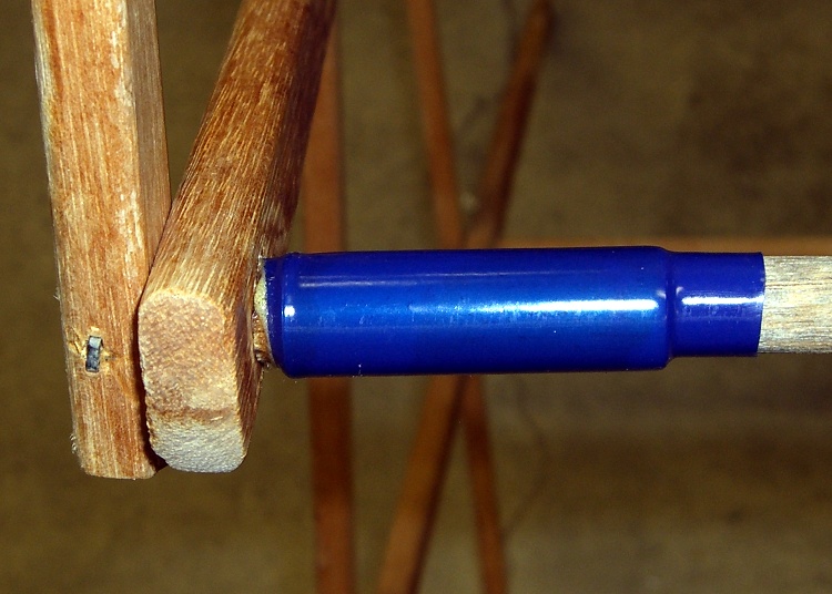
Vibration is a real killer for bike-mounted hardware. The antenna mast on my bike has been unscrewing itself, despite my repeated attempts to tighten it. Fortunately, I’ve managed to notice the rattle before the mast falls off into traffic.
We’ll see if a dab of medium strength (blue) Loctite will do the job.
One thing to worry about: this is an electrical as well as a mechanical joint. I hope there’s still enough metal-to-metal contact to get RF energy to the radiating part of the whip!
[Update: Yup, works just like you’d expect. Problem solved.]
The antennas on the other two bikes have remained tight, so maybe it’s just that my riding style generates more vibration? Hard to imagine; it’s not like I venture off-road.
More details on the homebrew mount are there and how commercial mounts fail are there.
The unsightly masking tape wrap is where I attached a reflector for a (rare) after-dark ride a while ago. Making a set of bushings for the reflector clamps is a low-priority job in the queue right now.
Bezel bottom 3.3 mm thick, excluding depression on bottom surface
Screw head sticks out of depression 0.9 mm
Some deft work on the bezel installed in the camera, using the blunt end of a transfer punch, a pin vise, and a calculator reveals these protrusions:
1.4 mm does not trigger anything
2.1 mm triggers the half-pushed focus action
2.4 mm reliably triggers the shutter
So the new stem can stick out about 1.4 mm when the button is released and must not stick out more than 2.4 mm with the button fully depressed: a whopping 1 mm of travel!
Eyeballing the shutter release on my DSC-H5, that seems to be about right. I think it has more travel between “released” and “half pressed” than those measurements indicate, but it’s close. And sloppy, too: the H5’s button has a lot of side-to-side wobble, indicating that the stem is not a close fit in the bezel hole.
The screw head is 3 mm dia after being turned down and that’s about the right size for the nut that will adjust the travel distance, as it must fit into the recess in the bezel. The nut sets the protrusion when the shutter button is released: 1.4 mm.
The distance from the shutter button’s bottom to the bezel sets the travel from “released” to “click”: 1 mm, more or less. They’re held apart by the spring, so that’s the default state.
Circular Milling the Nut
I re-centered the 3-jaw chuck under the spindle, put a 1-72 nut on the turned-down screw, and applied some gentle manual CNC to convert the nut from a hex to a disk. The trick is to approach the nut from the right side (the +X side) and go clockwise around it (climb milling), so that the cutting force tends to jam the nut against the screw head. Do it the other way and the nut will zip downward away from the cutter
Surprisingly, I got that right the first time.
Using a 2 mm end mill and figuring a 2.9 mm final diameter, the radius of the circle to move the end mill around the nut is: R = (2.9 + 2.0) / 2
So the G-code for one pass looks like:
#<R>=[[2.9+2.0]/2]
G1 X#<R> F150
G2 I[0-#<R>]
Shutter Button Parts
Now, given the fragility of that setup, you don’t cut it all at once. You start from a diameter of maybe 4 mm and go down by 0.2 mm until you hit 3.0, then make a final pass at 2.9 mm. EMC2’s AXIS MDI mode makes this easy enough: type in the commands for a pass at 4.0 mm, then click on the previous command, change 4.0 to 3.8, and then just clickety-click.
Spindle far too slow at 3000 RPM, feed at 150 mm/min seemed fine. Sissy cuts worked out OK.
After the first few passes, my dim consciousness became aware of the fact that this is how I should have turned down the screw head…
Button Assembly – Top
I cleaned up the bezel by putting it in an ultrasonic cleaner to shake the crud off, put it on a warm firewall router overnight to dry it out, then slobbered some Plastruct solvent adhesive into the cracks and clamped it for another night. The bezel was slightly out-of-round from the damage, so I hand-trimmed the bent plastic using a “high speed cutter” (#193, basically an end mill) in a Dremel flexible shaft at about 1/3 max speed until the shutter button bottomed out smoothly within the inner recess. Not a bit of CNC to be seen: hand held all the way.
Button Assembly – Bottom
Then loosen the nut a bit, poke the screw through the bezel, put the spring on, and screw the shutter button in place. Adjust the nut so the screw head is 1.4 – 1.5 mm from the bottom of the bezel with the nut resting in the recess.
Button Assembly – Pressed
Twiddle the shutter button until the screw head protrudes 2.4 mm from the bezel with the button pressed down.
That’s measured with the hole-depth tang of a caliper, sitting atop the screw head. I don’t believe there’s 0.1 mm accuracy in the measurements, but they’re close enough. I did file off a few mold flash bumps from the shutter button & bezel during this adventure.
Mark the screw threads above the button, unscrew it, chop the screw off with a stout diagonal cutter (it’s brass and not very thick, it’s OK), file the end flat, clean up the threads.
The trick seems to be that the button must rest just below the inner ring of the bezel, so that it bottoms out smoothly when pressed. If it’s above the ring, then one side will hang up. The ring depth thus seems to limit the maximum travel, although I can’t say whether this is the way it’s supposed to work or not.
I iterated & filed until the screw was flush with the top of the button with it screwed down to the proper position. It helped to figure out that one turn of the shutter button on the screw changed the “pressed” protrusion by 1/72″ = 0.35 mm.
Urge some low-strength Loctite under the nut and into the shutter button’s hole, reassemble everything, and you’re done.
Urethane Adhesive on Body Socket
The fall bent the bezel tabs so they no longer latch firmly in the camera body. I put two dabs of urethane adhesive on the socket in the body. The adhesive expands (foams!) as it cures; I hope it will lock the bezel in place while still allowing it to be removed if needed.
I dabbed off most of the adhesive you see in the picture before installing the bezel; it’s not as awful as it looks!
The final result has slightly less travel than the (undamaged, original) shutter button in my DSC-H5, but it works perfectly: half-press to focus, full press to trigger the shutter.
Having figured out what to do, I started with the button, which is chromed plastic, nothing too fancy, and not at all hard to machine.
Laser Aligning to the Button Stem
A small post turned from an acrylic rod (the gray cylinder) supports the button in the Sherline 3-jaw chuck attached to the mill table; that was the only way to keep it reasonably level. Laser alignment got eyeballometrically close to the middle; it looks a bit off to the right, but the end result was OK.
Removing the Broken Stem
A 2 mm end-cutting bit chewed off the stem in short order; I set the jog speed to about 100 mm/min and just jogged down until the cutter was flush with the button. Spindle at 4000 rpm, for lack of anything smarter.
I decided to go with a 1-72 brass machine screw, which is slightly larger (1.75 mm) than the original 1.5 mm button stem. That means I must drill out the bezel hole, as well, but the 1.5 mm diameter of the next-smaller 0-80 screws in my assortment was a sloppy fit.
A touch of manual CNC for the drilling, #53 with the spindle at 3000 rpm, Z touched off at the button’s surface:
G81 Z-4 R3 F150
The spindle was slow enough and the feed fast enough to keep from melting the button without applying any coolant.
I tapped the hole 1-72 by simply screwing the tap in with my fingers…
Chuck-in-chuck For Head Shaping
The 3-jaw lathe chuck doesn’t grip a 1-72 screw (no surprise there), so I grabbed the screw in the Sherline’s smallest drill chuck and poked that in the lathe. This doesn’t make for great concentricity, but it was close enough. The right way, as my buddy Eks reminds me, is to slit a nested bunch of brass tubing and use them as collets, but … next time, fer shure.
Button With Reshaped Screw Head
Anyhow, here’s what the button & screw look like so far. The backside of the screw head looks like it needs some cleanup; there’s nothing like taking a picture to reveal that sort of thing.
The pencil lead is 0.5 mm and the grid in the background has 1 mm squares, just to give you an idea of the scale.
My brother-in-law Tee dropped his Sony DSC-H1 camera, which landed atop its shutter button on the pavement.
Bad news…
the shutter button broke off
the bezel popped out
the teeny little snap ring that held the shutter button stem in the bezel vanished, because…
the stem broke and the end vanished, too
Good news…
apart from some scuffs, the camera still works
he managed to find the shutter button
and the button bezel
and the spring!
Shutter Button – Spring – Bezel
A bit of browsing reveals that many, many Sony DSC-Hx (where x is an integer from 1 through 9, inclusive) owners have the same problem, minus the inconvenience & embarrassment of first dropping the camera. Turns out that the shutter button stem breaks at that notch in normal use.
It seems the stem snaps while you’re taking pix, whereupon the spring launches itself and the button cap into the nearest river / drain grate / weedy area, never to be seen again. Tee is exceedingly fortunate to have found all the major pieces!
Shutter Button Stem – End View.
Here’s the broken end of the stem, with the button cap out of focus in the background. The stem is 1.5 mm in diameter, so the snap ring was surrounding, what, 0.75 mm of plastic? In what alternate universe did this design decision make sense?
I think the snap ring contributed to the problem by eroding the stem in the notch; that little white stub isn’t half of the stem diameter; it may have stretched under impact, but surely not all that much.
Yes, you can buy a replacement button for about 30 bucks direct from Sony, but it seems the new stem is subject to the same failure after a short while. They’re standing by the original design, marginal though it may be.
Now, obviously, this stem failed from abuse, no argument there. Everybody else had their stem fail without provocation, though, so it really isn’t adequate to the task at hand.
Bezel Socket View
Anyhow, there’s also some damage at the bezel socket on the camera body, but nothing major. The dented silver areas on either side of the switch membrane are ESD shields, so that any static discharge from your finger will (most likely) dissipate on the external frame of the camera, rather than burrow into its guts via the switch.
The bezel twist-locks into the camera body, which means that you can remove the bezel if you can get a good grip on it. It turns clockwise to remove.
Shutter Switch Closeup
Peering closer at the membrane switch, it looks as though the button stem did some damage on its way out, although Tee admits to using various pointy objects to trigger the shutter while figuring out what to do with the camera.
More good news: the switch still works correctly, including the focus function with the button half-pressed, That means the switch membrane and contacts are in good shape.
Bezel – Top View
The bezel itself is pretty well graunched, with a nest of cracks underneath that damaged arc to the left of the pictures. I think it’s in good enough condition that I can remove the bent plastic, ooze some solvent adhesive into the damage, and compress it enough to make everything stick together.
Bezel – Side View
Obviously, this calls for some Quality Shop Time!
The overall plan is to remove the remaining stem from the button, drill-and-tap the button head for a miniature brass screw (1-72, I think), reshape the screw head into a membrane-friendly plunger (about 3 mm diameter and flat), then put it all back together with a nut in place of the snap ring.
I should be able to install the bezel (without the button), then insert some drill rod through the hole to figure out how far the screw must protrude to trigger the focus & shutter switches. Perhaps a pin vise will grip the drill rod and bottom out on the bezel’s central ring, so I can do a trial-and-error fitting?
Then I can adjust the screw to that overall length below the bezel with the button pressed, whack off anything that sticks out above the button, adjust the nut to limit the button’s outward travel, slobber Loctite over everything, and put it all together for the last time.
That’s the plan, anyway. As the Yiddish proverb has it, “If you wish to hear G*d laugh, tell him your plans.”
There I was, bandsawing a 24″-diameter circle from 3/8″ plywood when the saw stopped cutting… which is how the bandsaw tells me that the blade joint just came undone. That’s what I get for applying too much torque to the blade, I thought…
As you can see, the joint I described at great length there wasn’t nearly as good as I thought. It has a nice wetted spot in the middle, but the rest of the joint didn’t bond. Alas, the ends of the blade sections had just enough molten solder to look as though they were bonded.
I’ve done other joints with that resistance soldering unit which held up well, but I’ll cheerfully admit I don’t have years of deep experience with it. Given the effort involved in making a bandsaw blade joint (not to mention the fact that I only solder up a new blade when I really need one), this is the first destructive test I’ve seen. It’s not like I’m going to solder up a blade, then tear it apart just to see how it worked, as I did with the nickel strip on those AA cells there.
A change of technique seems in order. The carbon electrode produces enough heat directly under it (which isn’t surprising, that’s how resistance soldering works), so I must cover the full joint area with enough oomph to get a good bond everywhere. That seems to be 1.5 seconds per zap, more or less, repeated as needed.
I have some machinable graphite that I could cut to be one square bandsaw joint at the end, plus a stub from a searchlight electrode that might work with less overall effort. However, a larger electrode probably wouldn’t heat the joint enough to melt the solder everywhere at once.
For what it’s worth, I tried to re-solder the joint without doing full surface preparation by grinding down to bare steel. Didn’t work, natch, which should come as no surprise; wasted half an hour futzing around before I gave up and did it right.
Memo to Self: Use the carbon gouging rod electrode, hit the entire joint, and don’t move until each zap cools!