Ed Nisley's Blog: Shop notes, electronics, firmware, machinery, 3D printing, laser cuttery, and curiosities. Contents: 100% human thinking, 0% AI slop.
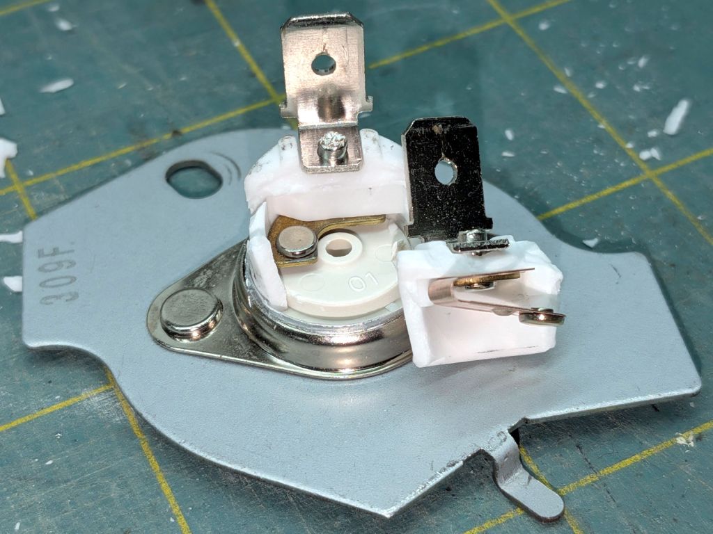
I don’t know what permanently opens the circuit in there, but it definitely happened. The contacts remain unblemished, so they were pressed firmly together until the end.
With nothing to lose, I reinstalled the Thermal Cutoff I removed last year (*) and the dryer works fine again.
It is possible lint accumulating in the filter bag I added to the exhaust vent restricted the airflow enough to overheat the cutoff, but the Operating Thermostat should keep the air around 155 °F and the Hi Limit thermostat should have tripped at 250 °F, long before the temperature reached 350°F.
Another cutoff will arrive shortly and will remain in the Box o’ Dryer Parts against future need.
(*) Which is why I keep the old parts around, because a dubious part on hand is much better than the new part I might not be able to get due to, oh, “supply chain issues”.
Our square oak stool developed an annoying creak in two of its legs, resulting in a teardown & glue-up.
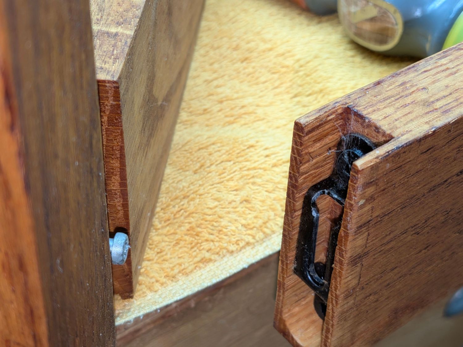
The legs come in pairs held in place by snug screw fittings:
Oak Stool Legs – mechanical joint
The screw on the left slides into the tapered fitting on the right and latches firmly in place: no creaks in there! I have no idea what that fitting is called; my search-fu is unavailing.
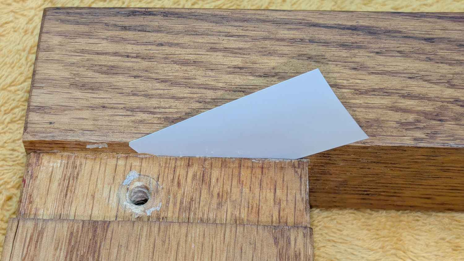
In any event, the offending legs were loose enough to admit a 6 mil = 0.16 mm miniblind snippet shim:
Oak Stool Legs – loose joint
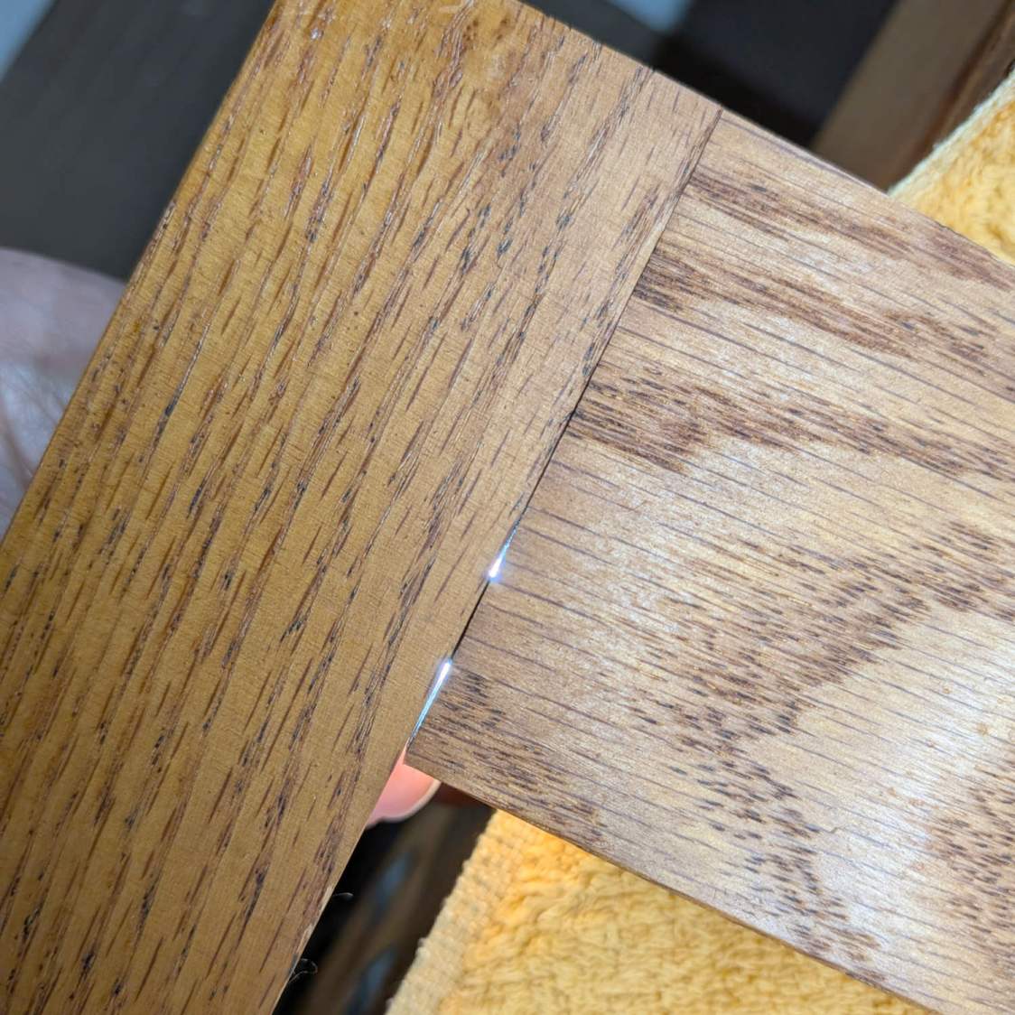
Our Young Engineer, having taken up woodworking as a serious hobby, suggested the joint might have a loose dowel, which will be difficult to fix. Peering into the gap with a flashlight below showed that was the case:
Oak Stool Legs – dowel revealed
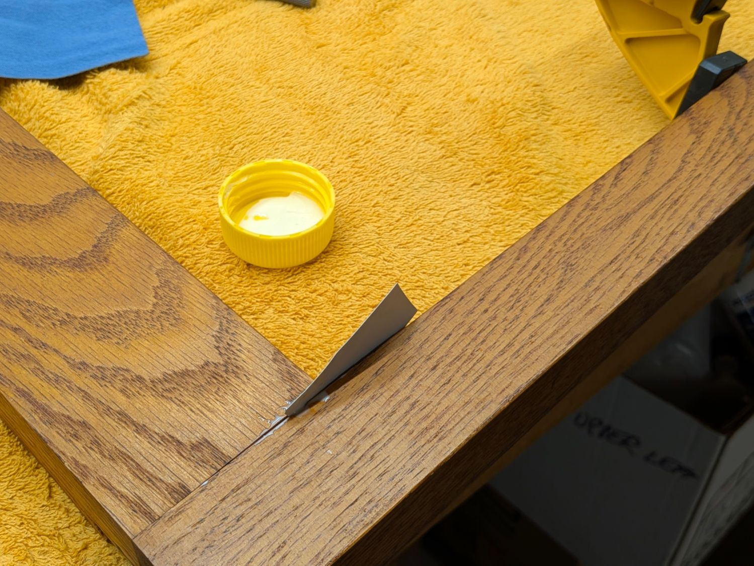
While it might be possible to force the joint apart enough to properly re-glue the dowels, I opted for a half measure by applying a spreader and easing wood glue into the gaps using the shim:
Oak Stool Legs – gluing
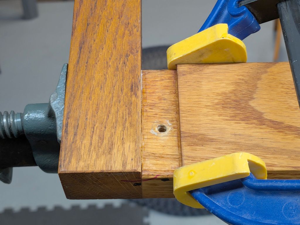
An overnight session with the pipe clamp eliminated the creak, at least for now:
Oak Stool Legs – clamping
The blue-and-yellow clamp fixed the loose splinter you didn’t notice in the second picture.
Traces of glue along inside the joints suggest I’d done something like in the deep past. Ideally, I’ve learned enough to get it right this time.
This file contains hidden or bidirectional Unicode text that may be interpreted or compiled differently than what appears below. To review, open the file in an editor that reveals hidden Unicode characters.
Learn more about bidirectional Unicode characters
Most of the PolyDryer boxes had the same humidity as before, so I didn’t disturb them. When the humidity starts to rise, then we’ll see what’s going on in there.
The PETG Orange meter continues to misbehave and has been glitching from 22% to 30%. The indicator card shows the humidity is around 10% inside and the relatively low weight gain suggests there’s not much water to be adsorbed.
The PETG-CF Blue spool is new and, once again, shows filament does not arrive bone-dry in the factory wrapper.
Those two boxes now have alumina beads.
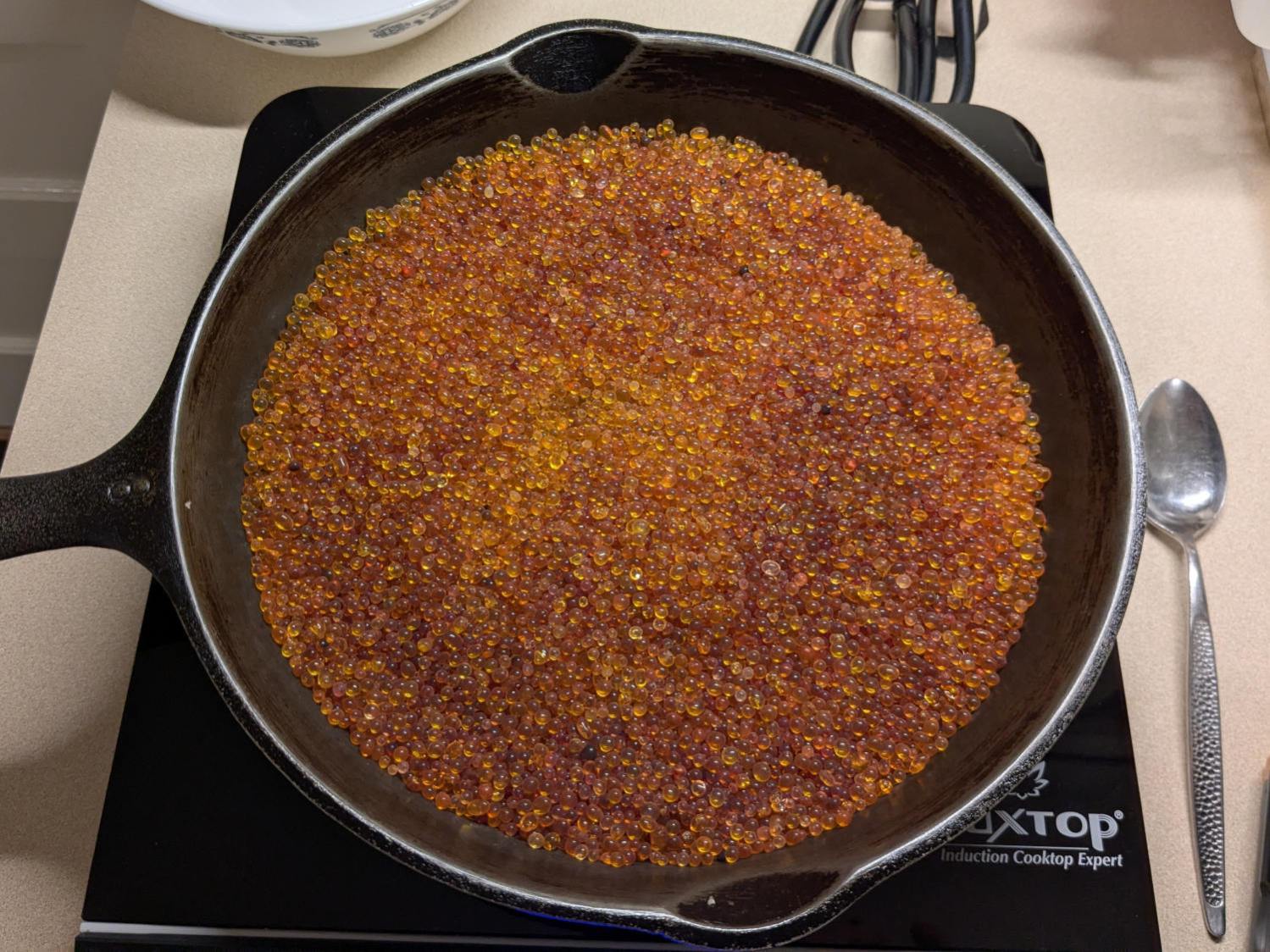
Dehydrating the jar of wet silica gel on the induction cooktop (set for 405 °F) sweated it down from 532 g to 503 g over the course of four hours, with nearly all of that change in the first two hours.
Obligatory photo from a while ago, because it looks pretty much the same now:
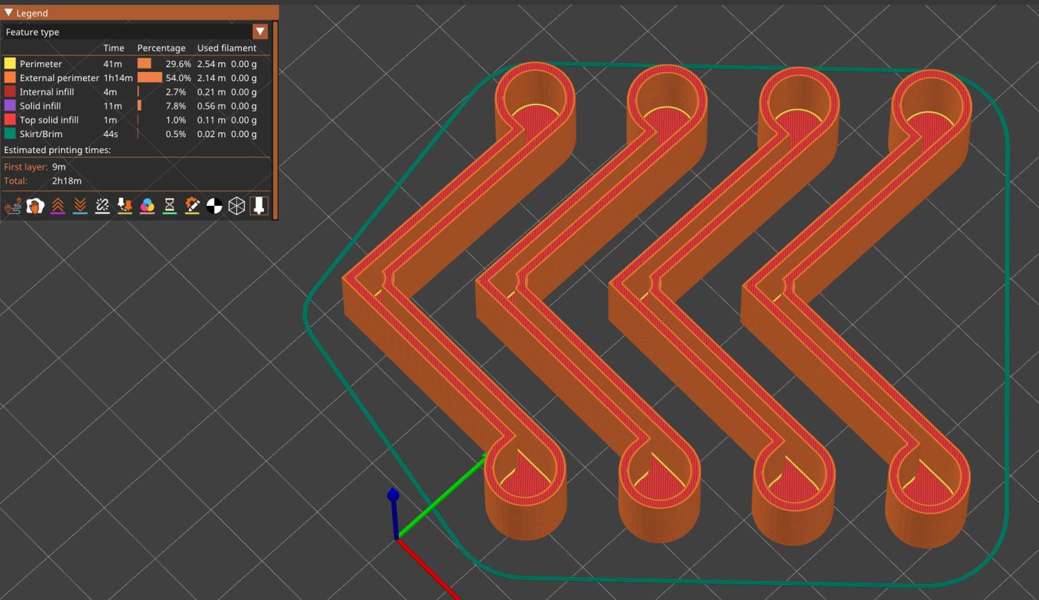
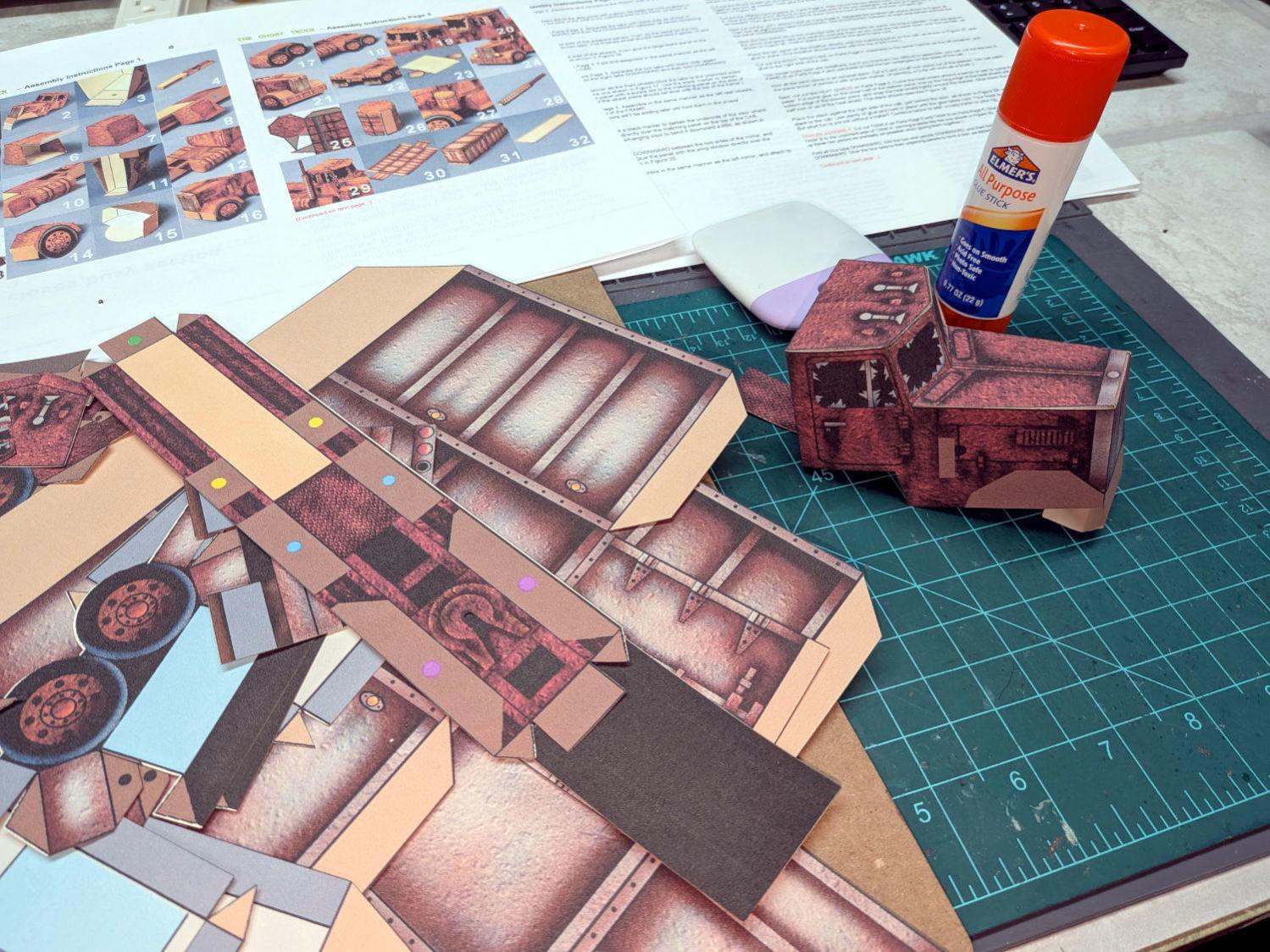
Having admired the paper craft at RavensBlight and with some experience in simple paper cuttery, I had to try my hand at the Ghost Truck. Rather than using an X-Acto knife and straight edge around the perimeter, I set it up for laser cutting.
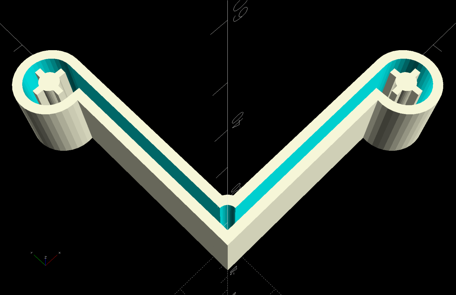
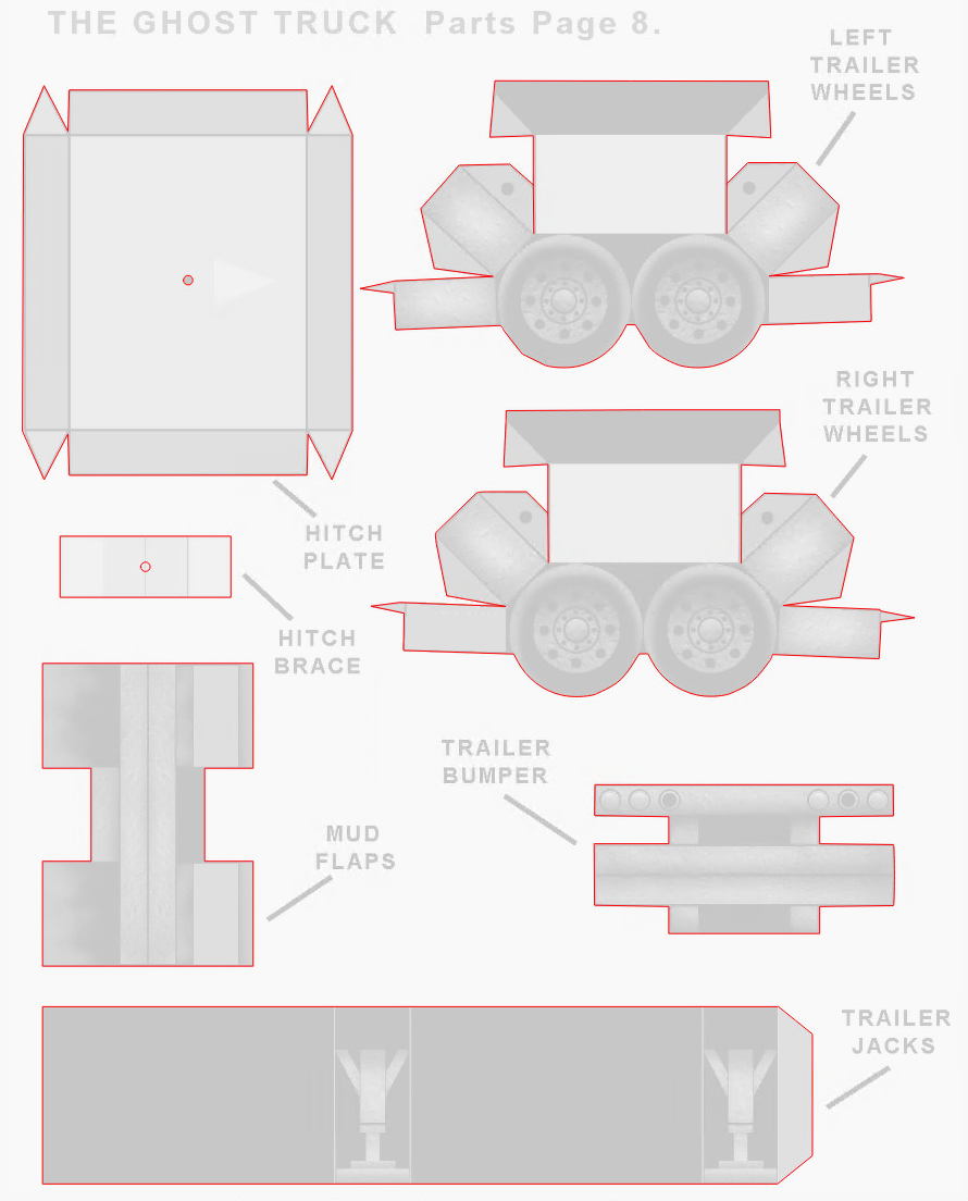
The instructions & layouts are images in PDF files, so it’s straightforward to import them into LightBurn and trace the outlines:
Ghost Truck – LightBurn vectors
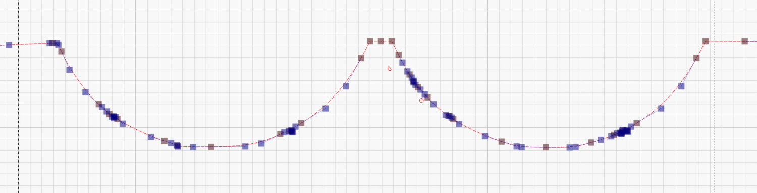
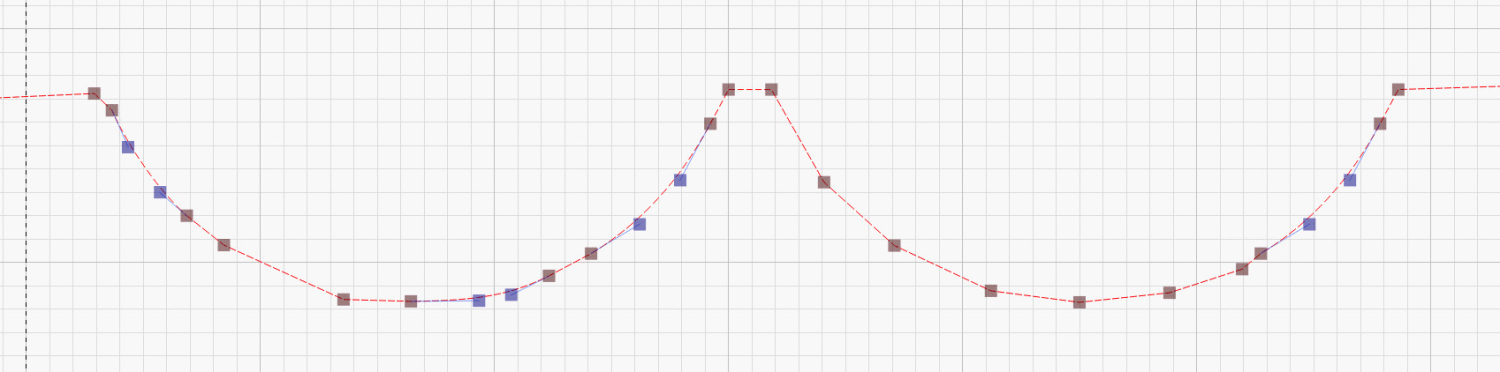
Tracing produces short vectors and irregular curves:
You must manually add any cuts buried in the pattern, as in the Trailer Wheels parts shown above, so pay attention to the instructions.
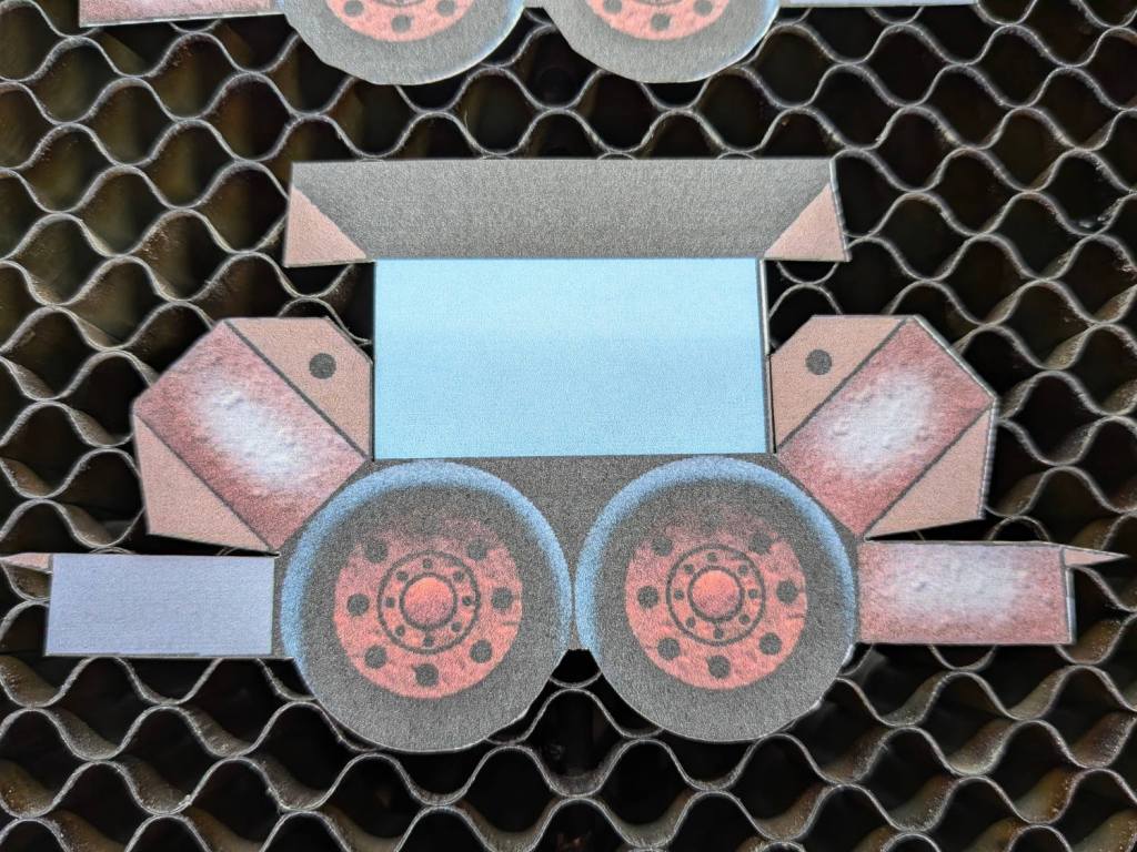
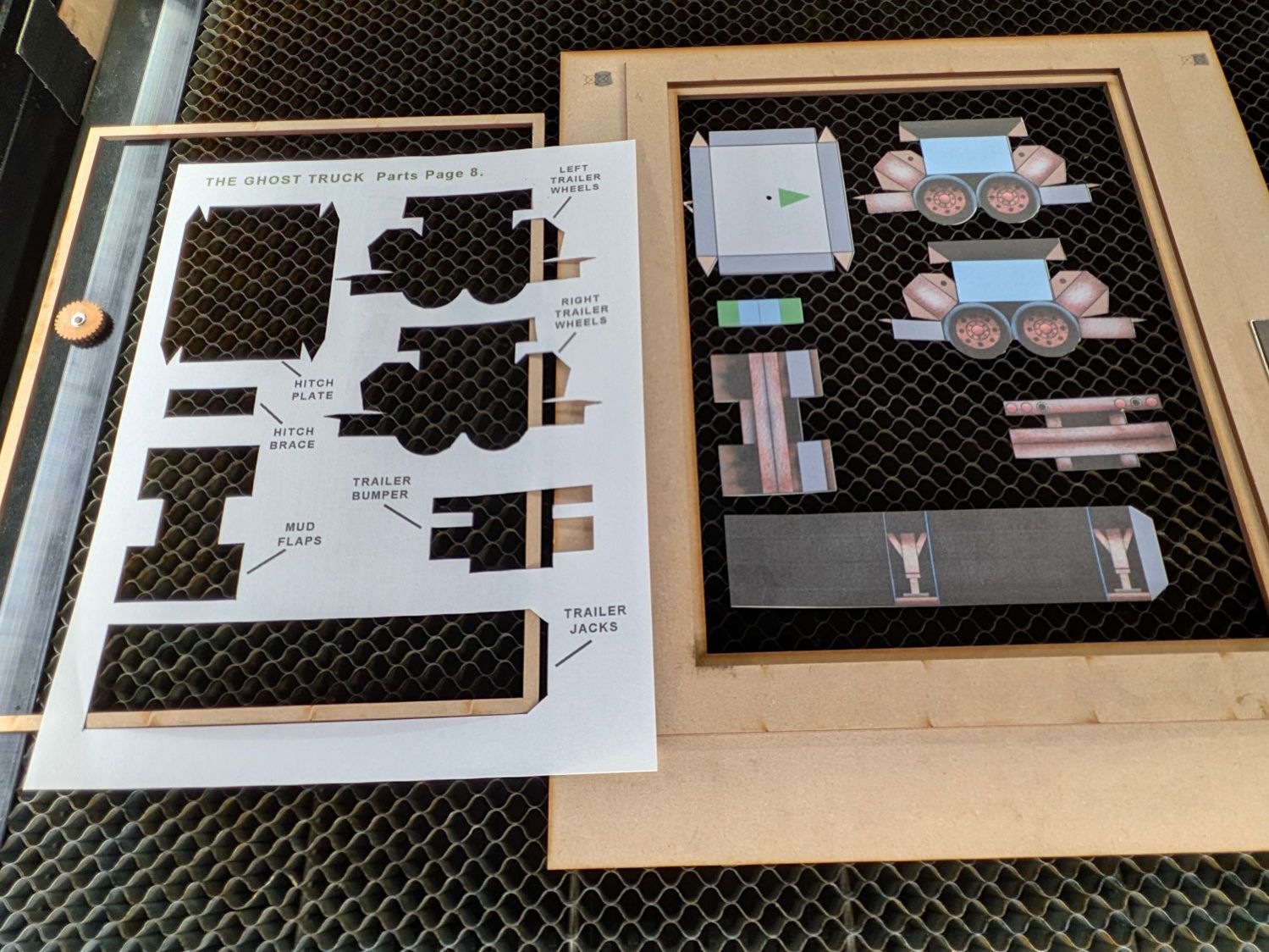
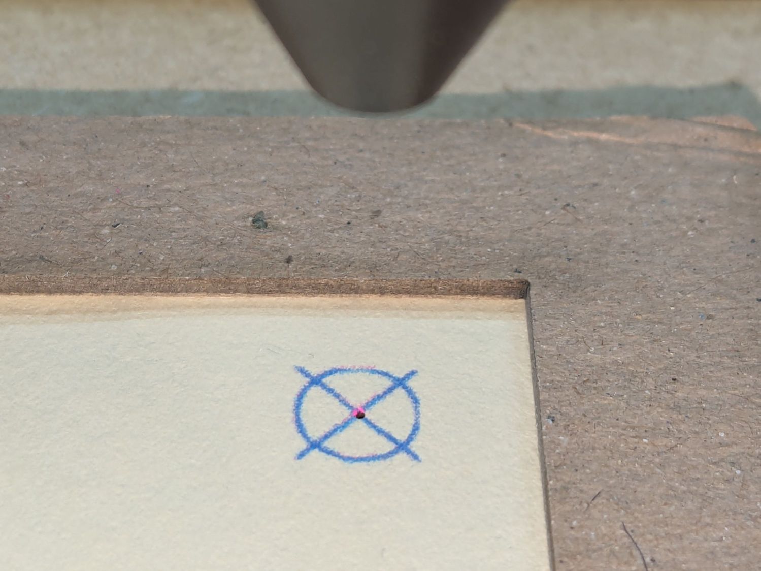
Use the Move Laser tool to put the laser head at an obvious point on the layout, then skootch the printed page (in a Letter size fixture) to put that point under the beam. Repeat for another point, iterate until satisfied, then Fire The Laser:
Ghost Truck – cutout overview
Some irregularities peek around the edges:
Ghost Truck – cutout detail
On the whole, it’s much better than I could do with a knife.
Repeat for the other seven pages of parts:
Ghost Truck – Assembly
With some diligence I may have it ready for All Hallows Eve …
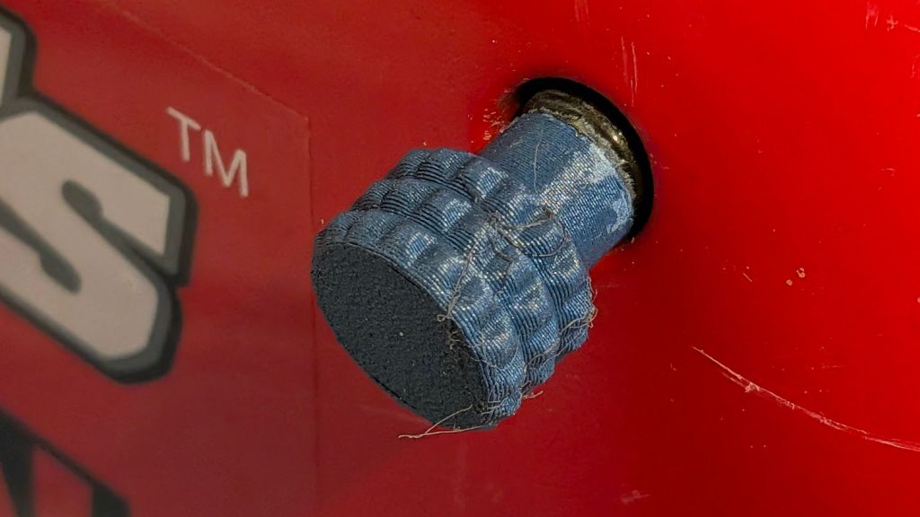
Although I got one of the screws out of the cover while modeling the knob, the other was more firmly implanted and resisted my entreaties.
However, having recently spotted the small tool kit accompanying the generator, should the knobs fall off again, I’ll forcibly remove the screws, put them in the tool bag, and rely on the snaps to hold the cover in place.
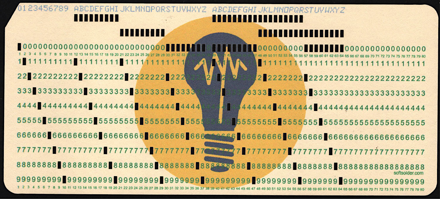
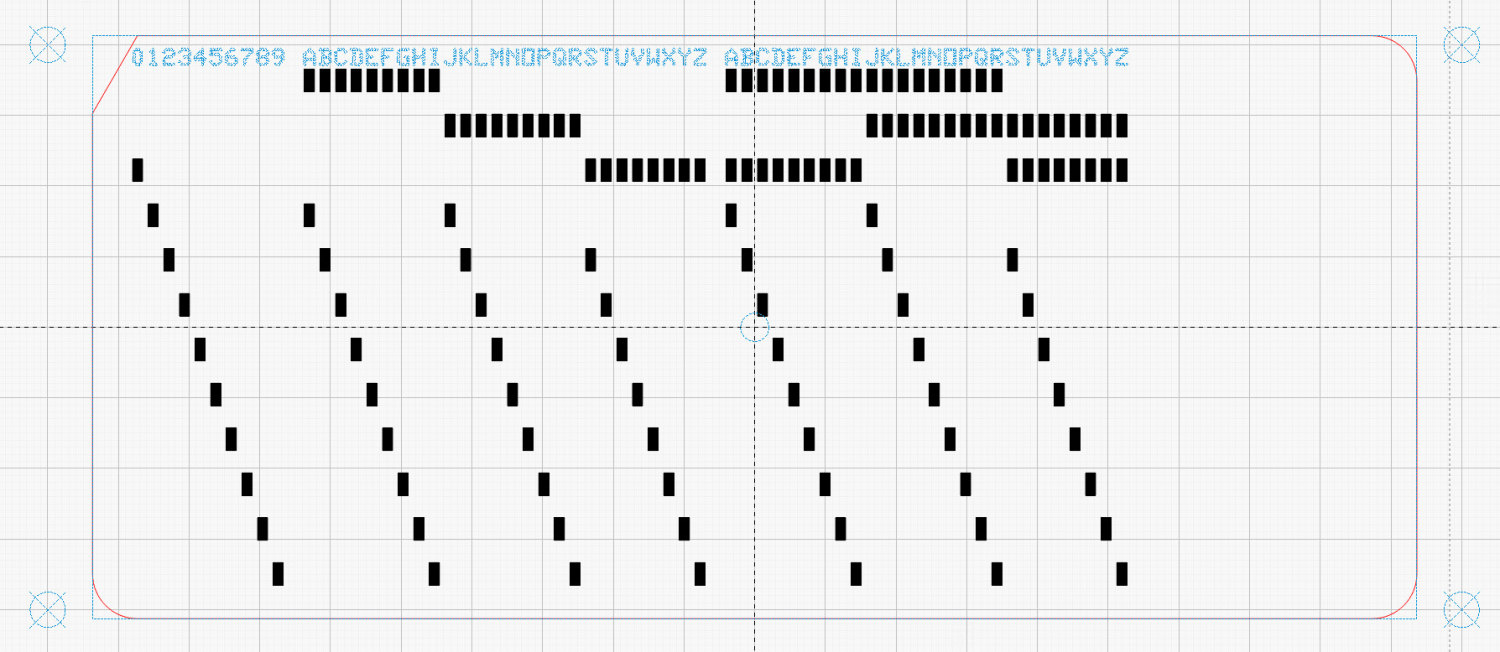
At last, I can make plausible-looking punched cards:
Test Card 3 – punched
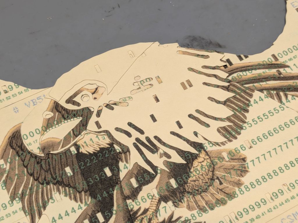
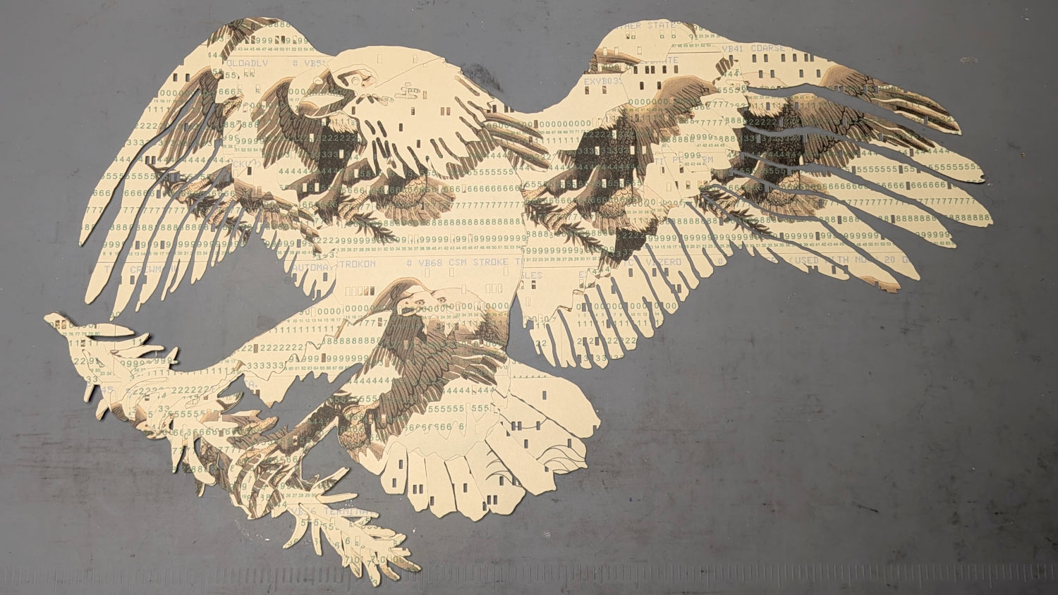
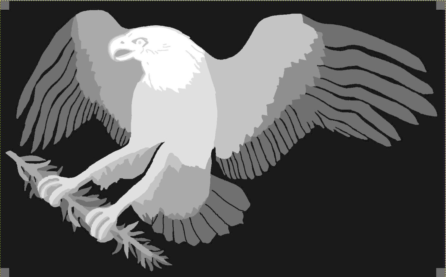
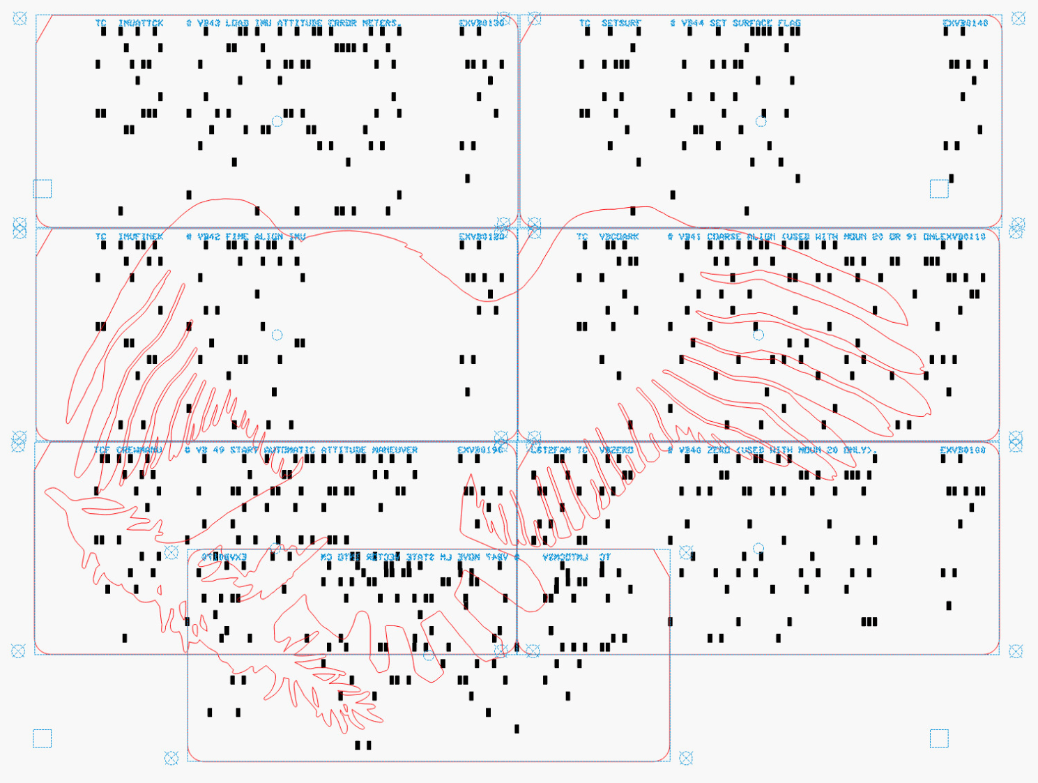
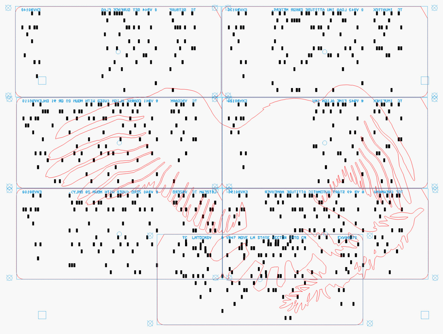
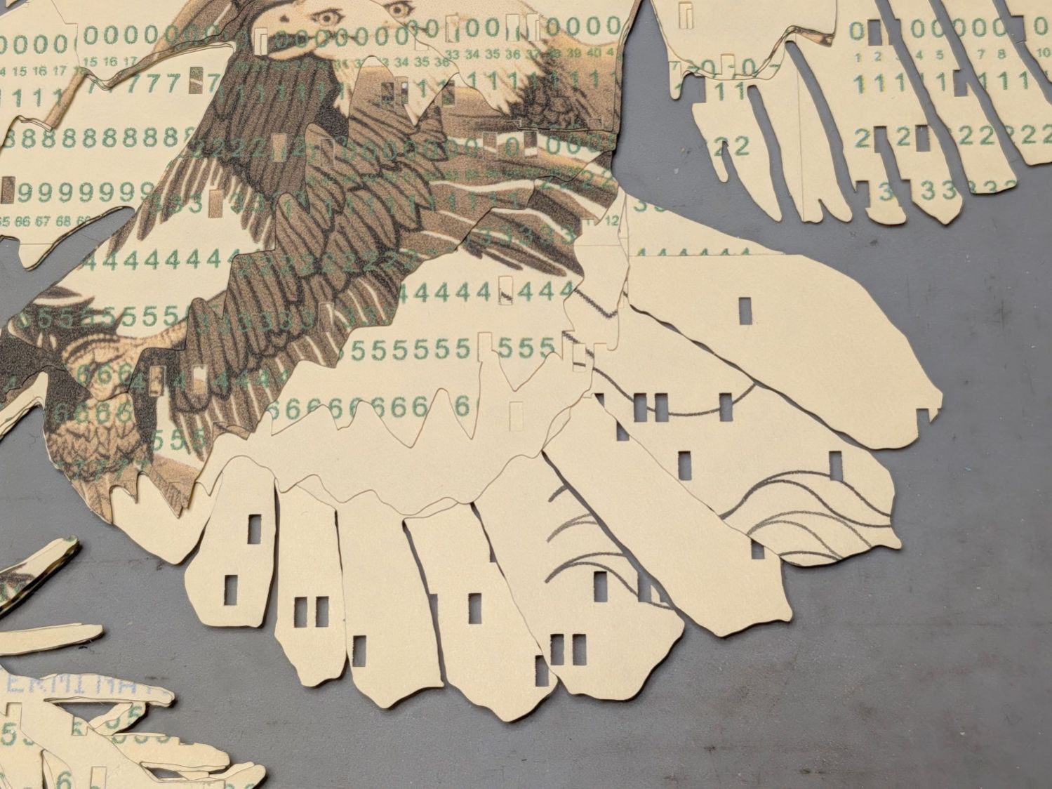
Then chop most of them up to make a layered eagle:
Apollo Eagle – V3 – overview
Back in the beginning, the grand overview explained the card production process, but now I can pull all the blog posts into a more coherent story.
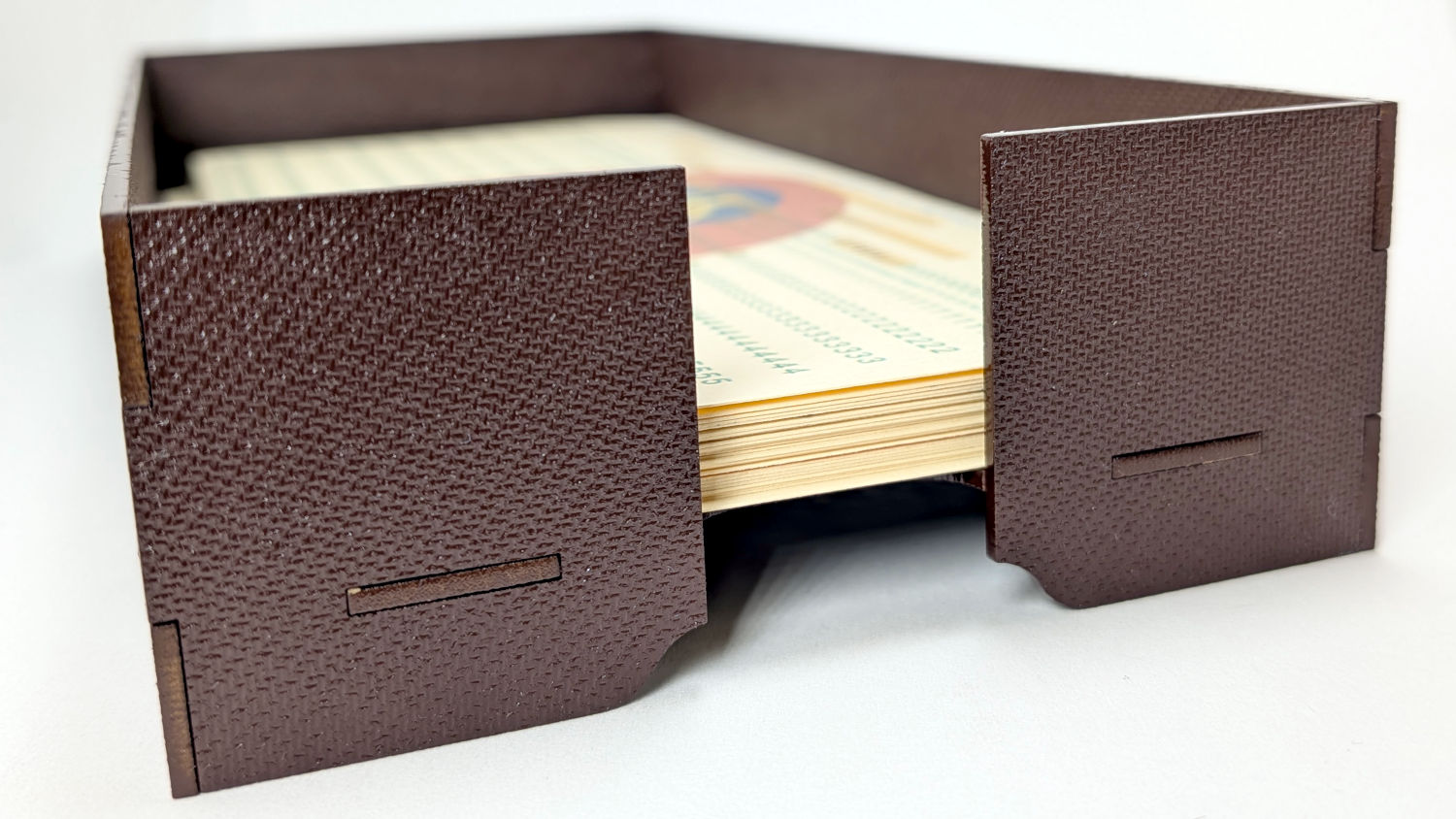
Start by making trays to hold the 1/3 Letter sized printed cards and the final cut cards. A coat of paint improves the result:
Card Storage Tray – front
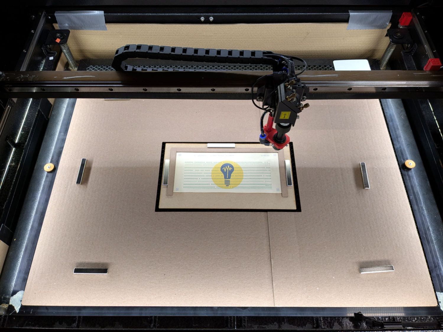
Then make a fixture to position the 1/3 Letter printed cards in the laser and a simple cover for the honeycomb to direct the air flow:
Punched cards – laser fixture overview
The current versions of the Python program to convert a line of text into the SVG images required to print and punch the cards, plus the Bash scripts handling all the command line parameters, are now in a single GitHub Gist . I used the source code from the Apollo 11 CSM AGC for historic reasons.
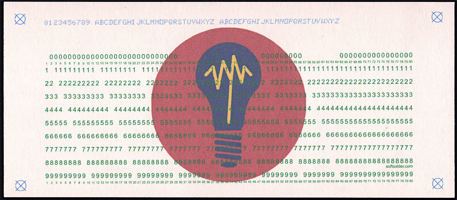
The Bash scripts invoke the Python program twice to produce both the printed layout:
Punched Cards – test card – printed
And “punched” holes surrounded by the perimeter cut for the laser:
Because my printer produces slightly off-size printed images, the script uses Inkscape to convert the SVG into a PNG, then downscales the image by a few percent (a different percent on each axis). It composites the card logo onto the PNG and slams the result onto a Letter page in the proper place to hit the 1/3 Letter sheets.