Our ancient Branson 200 Ultrasonic Cleaner began behaving erratically due to water seeping under the rather casual seal from last year’s fix. Although drying the switches let it start up again, it would run for only a few seconds before shutting down again, which suggested a deeper problem than just the switches.
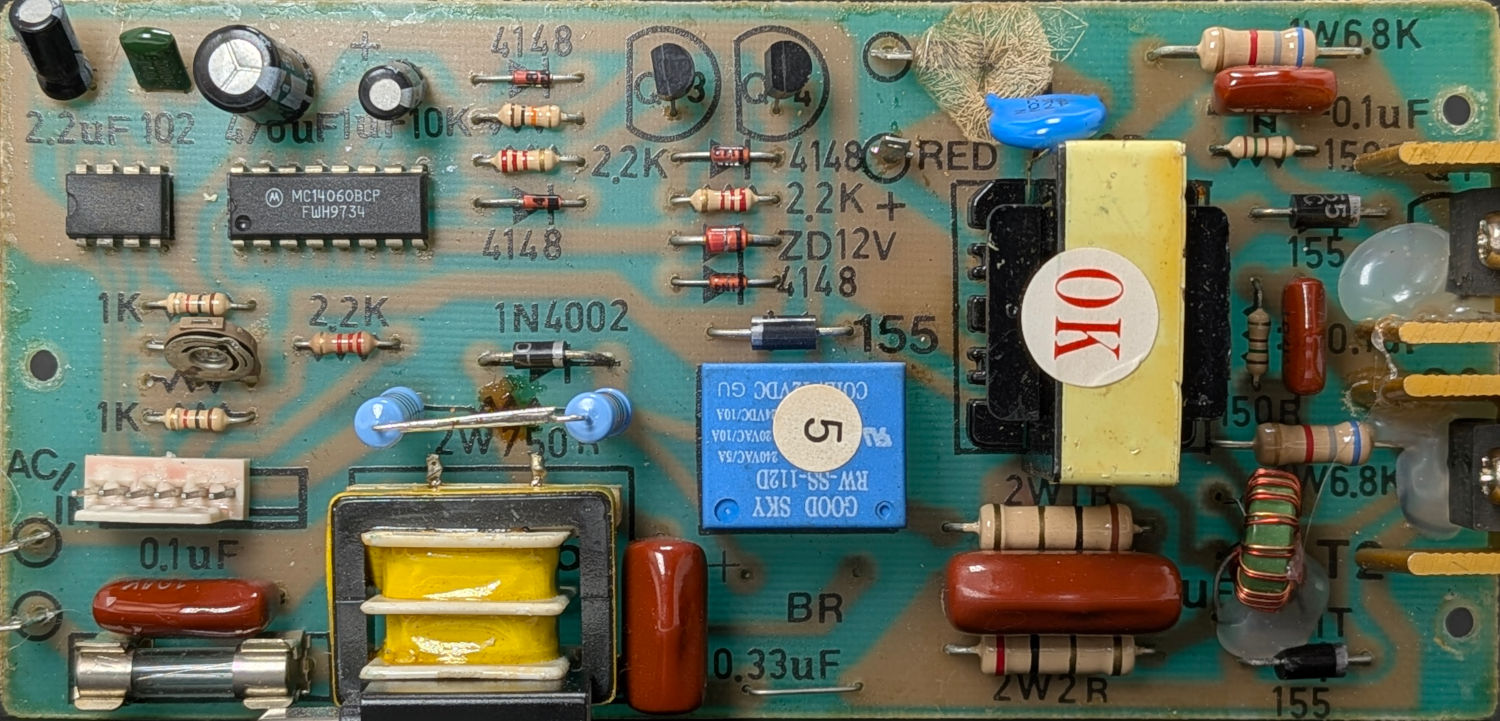
Take a picture of the PCB’s component side:
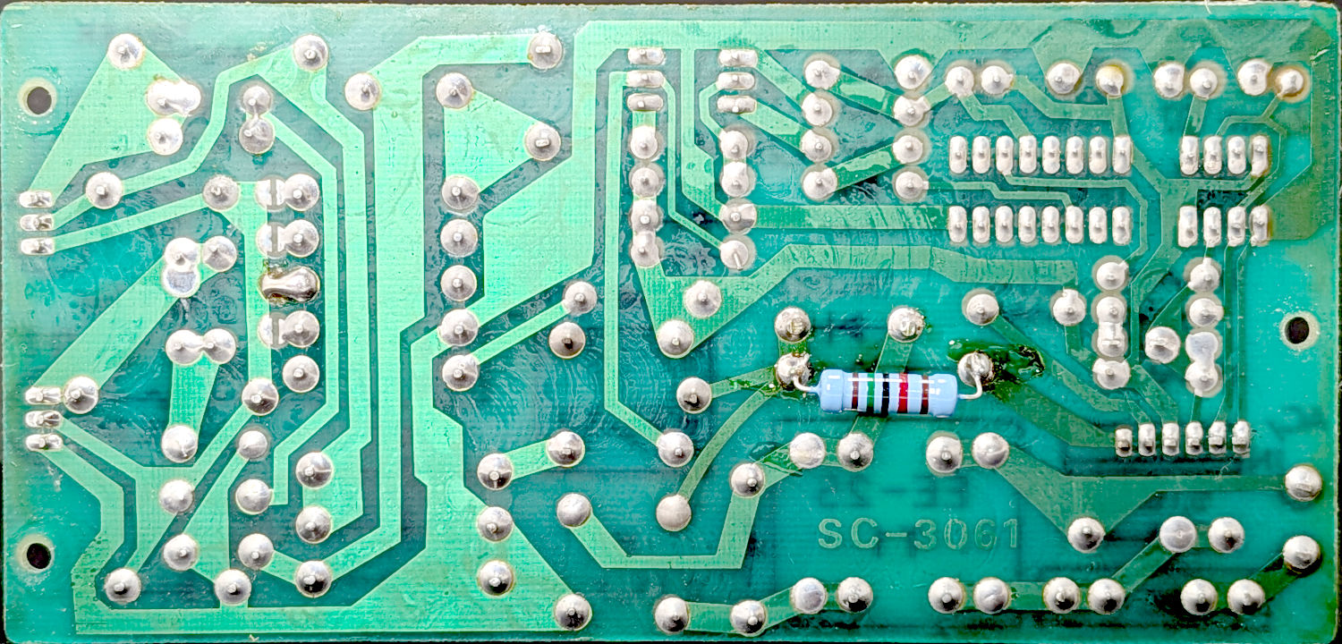
And of the solder side:
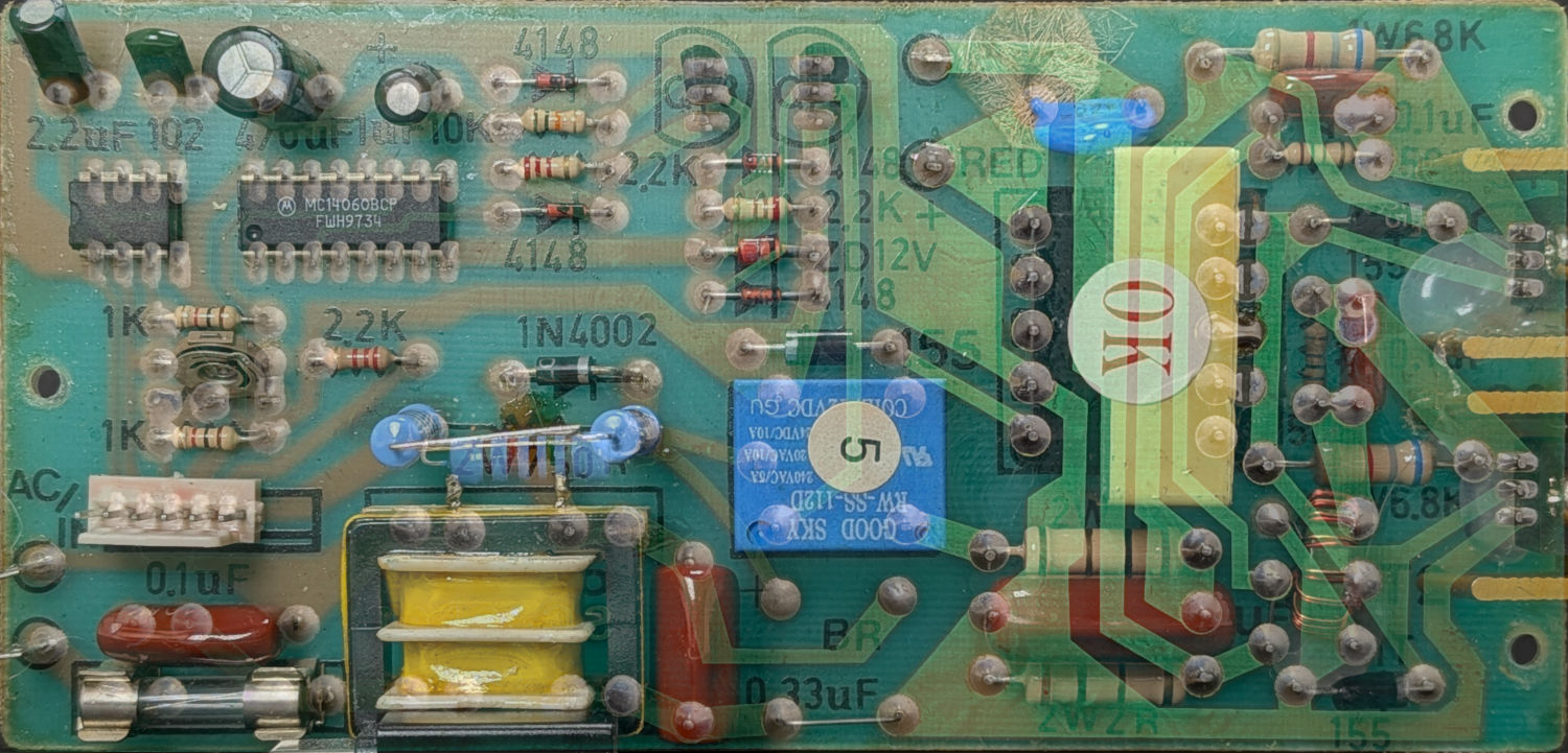
Transform those pictures to be the nice real rectangles shown above, resize to a common pixel format, mirror the solder side, turn it into a layer atop the component side, then tweak its opacity to make both sides visible at once:
Some pondering produces a partial schematic of the left half of the board:
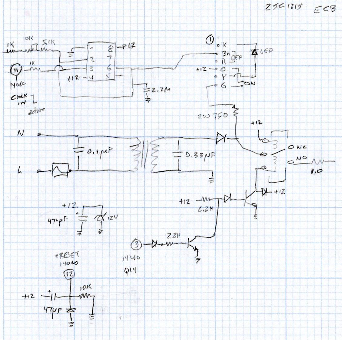
The 1:1 transformer is constantly powered, so the ON button connects the 120 V (!) half-wave rectified output to the +12V supply bus, with the 750 Ω resistor dropping most of the voltage while the switch is pressed.
The hotwired +12V supply forces the relay closed, which (in some as-yet unidentified way) fires up a +12V power source to hold the relay closed, with the 555 timer driving an MC14060 14-bit divider to count down the time until it turns itself off.
Reminder: this design dates back to the days when a pair of chips and a handful of through-hole components cost less than one of those fancy microcontroller thingies.
Plug the cleaner into an isolation transformer and trace the half-wave rectified signal through ON button to find it got all the way to the contact on the end of the orange wire in the connector, but did not reach the pin header on the PCB.
A closer look at the connector revealed a broken contact on the white wire, which I (rather crudely) soldered together while considering my choices:
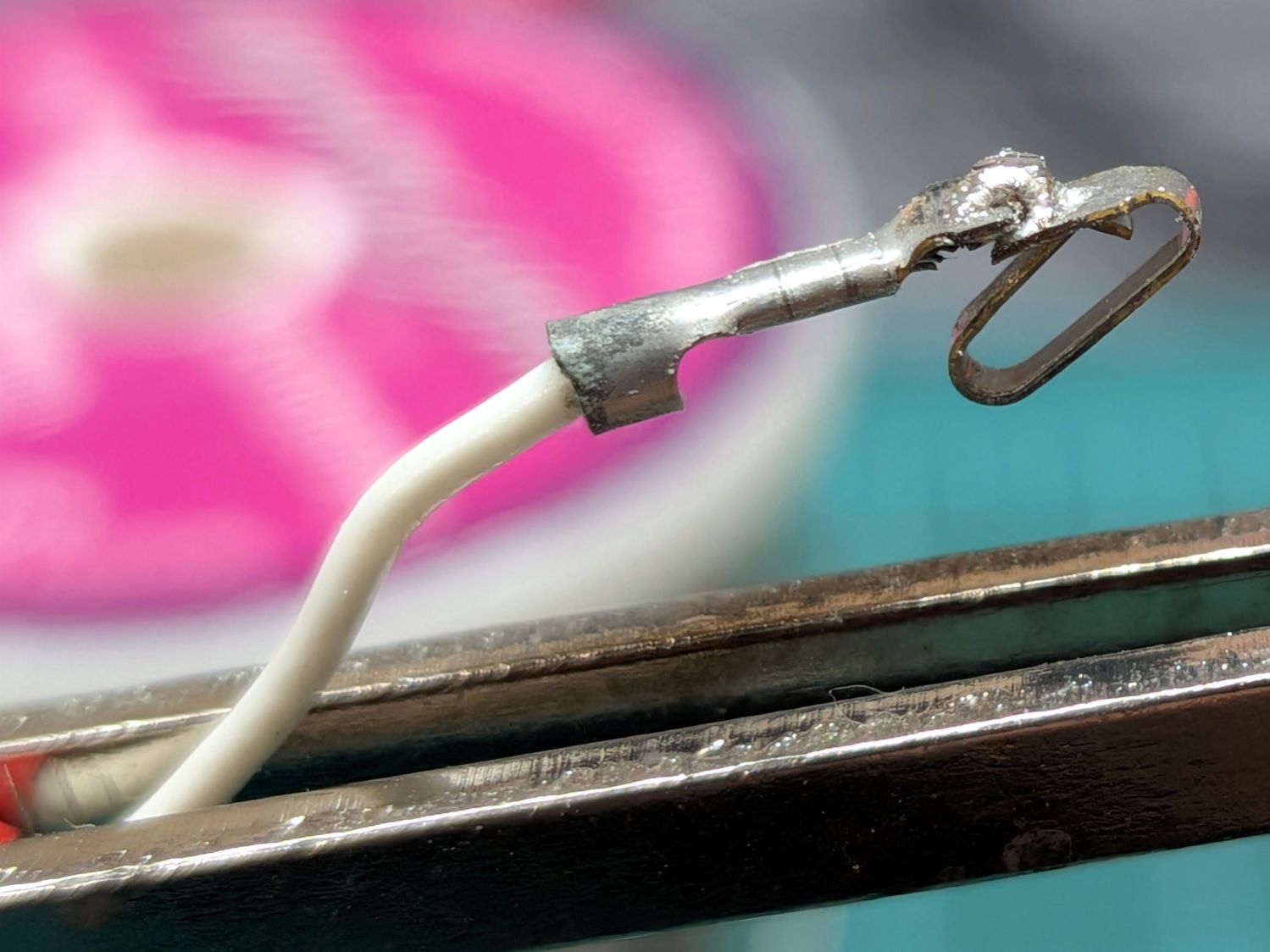
While plugging that wire back in place, this happened:
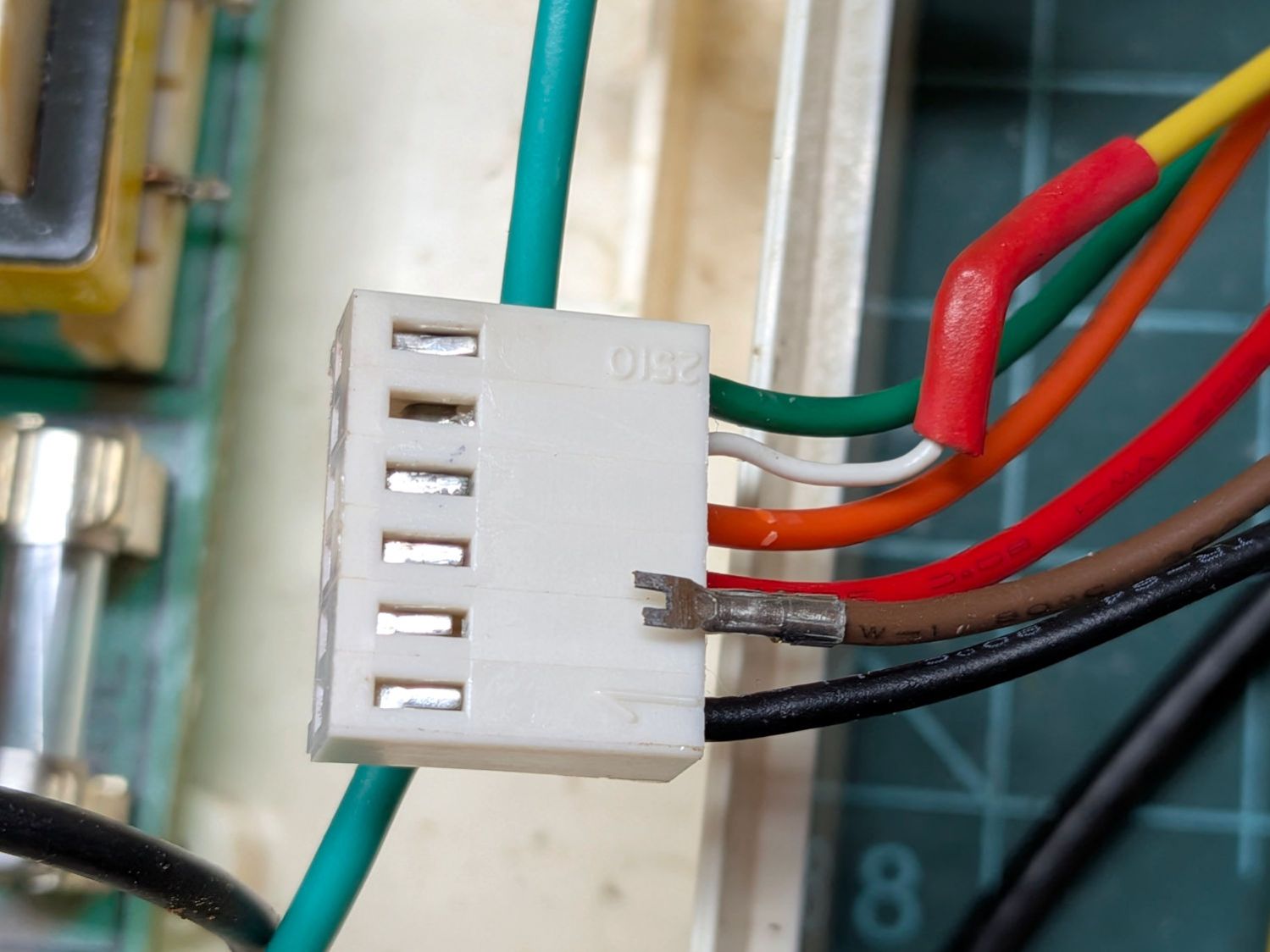
Neither of those are the (presumably) similarly failed orange wire, but even I can get a clue from three similar failures.
So I replaced the OEM connector with a JST-XHP 2.54 mm connector from an assortment I got for another project, replaced the chunky 22 AWG wires with flexy 26 AWG silicone wires in the same cheerful rainbow colors, and it began working perfectly again.
The buttons needed another water seal, so I tweaked the previous layout to kiss-cut GITD tape and through-cut colorful vinyl sheets:
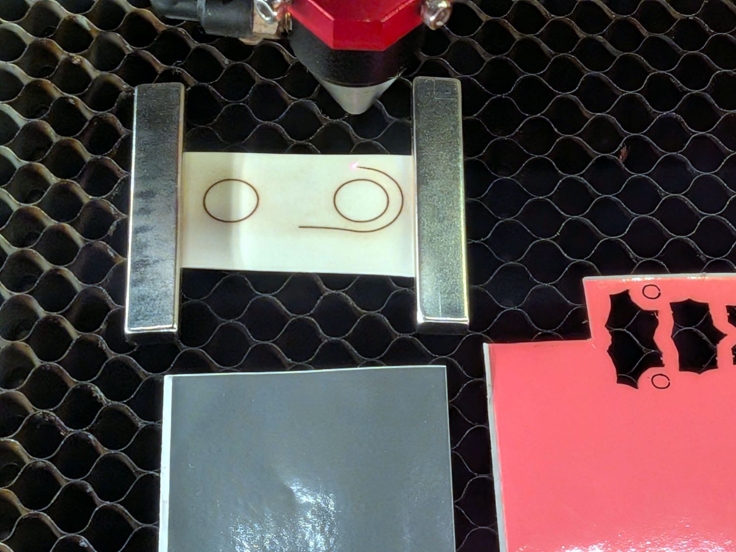
Capped with a transparent cover sheet cut from a pack of PDA screen protectors (remember PDAs?):
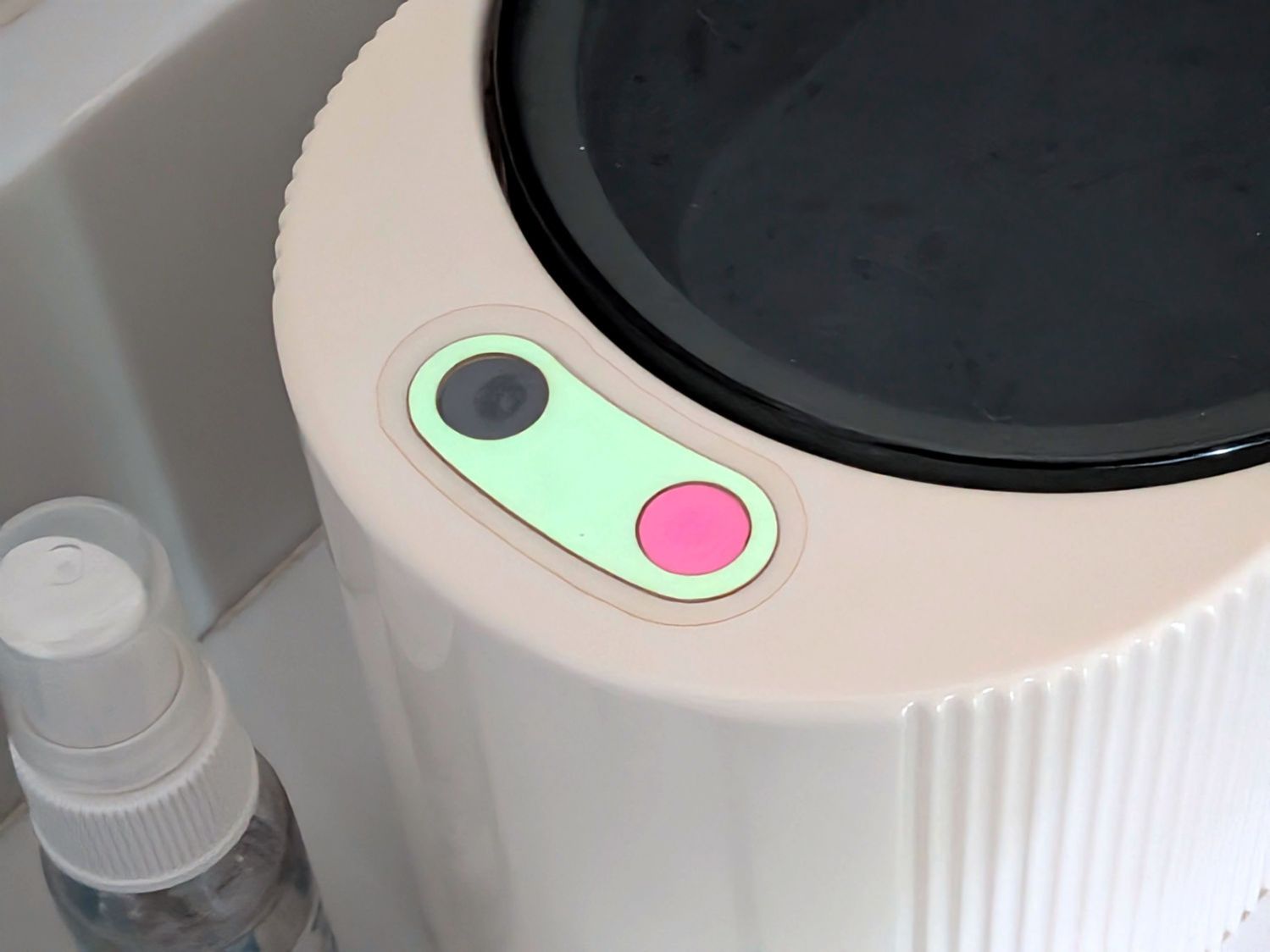
In truth, the GITD tape is too thick, so I’ll probably repeat this dance later this year.
FWIW, I was totally ready to buy a new ultrasonic cleaner, but all of them have scathing one-star Amazon reviews, to the extent I decided fixing this cleaner would be much easier than fixing a new one that’s been cheapnified to the point of no return. A common complaint seems to be water leaking into their capacitive switches and killing the circuitry stone cold dead: not an improvement over this one.

Spam comments get trashed, so don’t bother. Comment moderation may cause a delay.