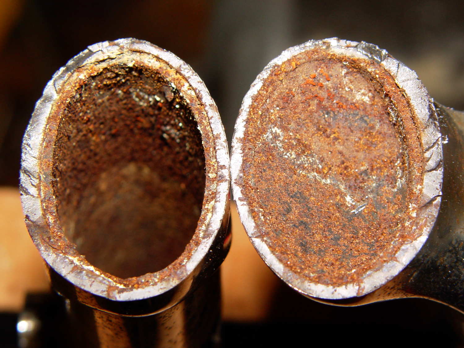
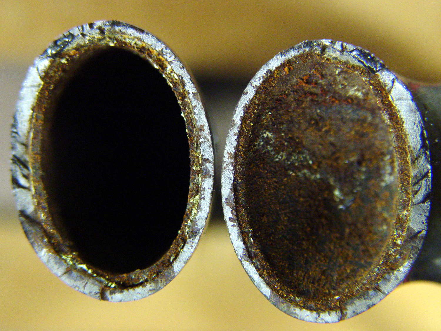
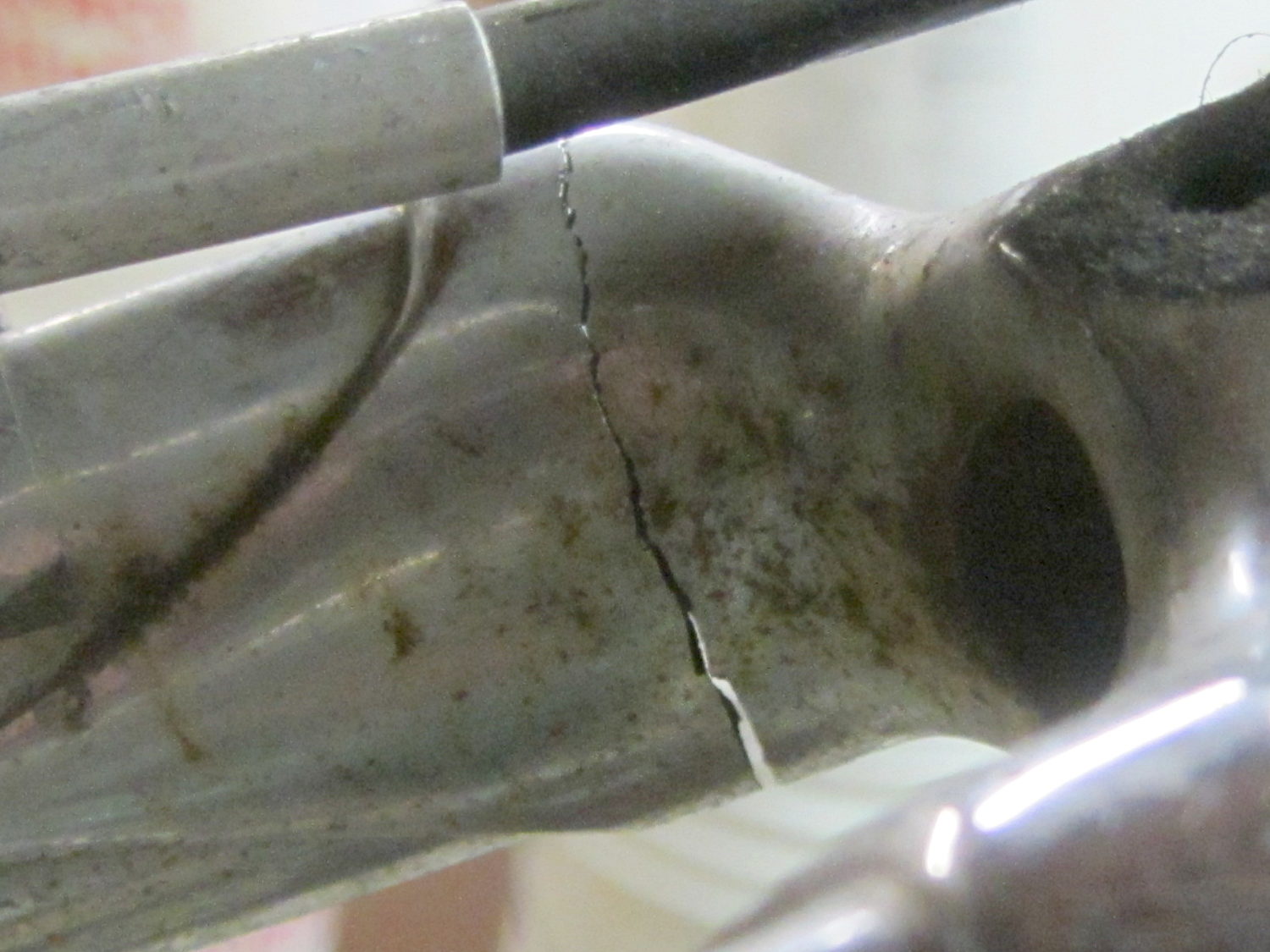
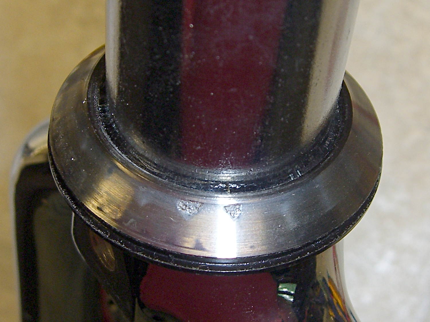
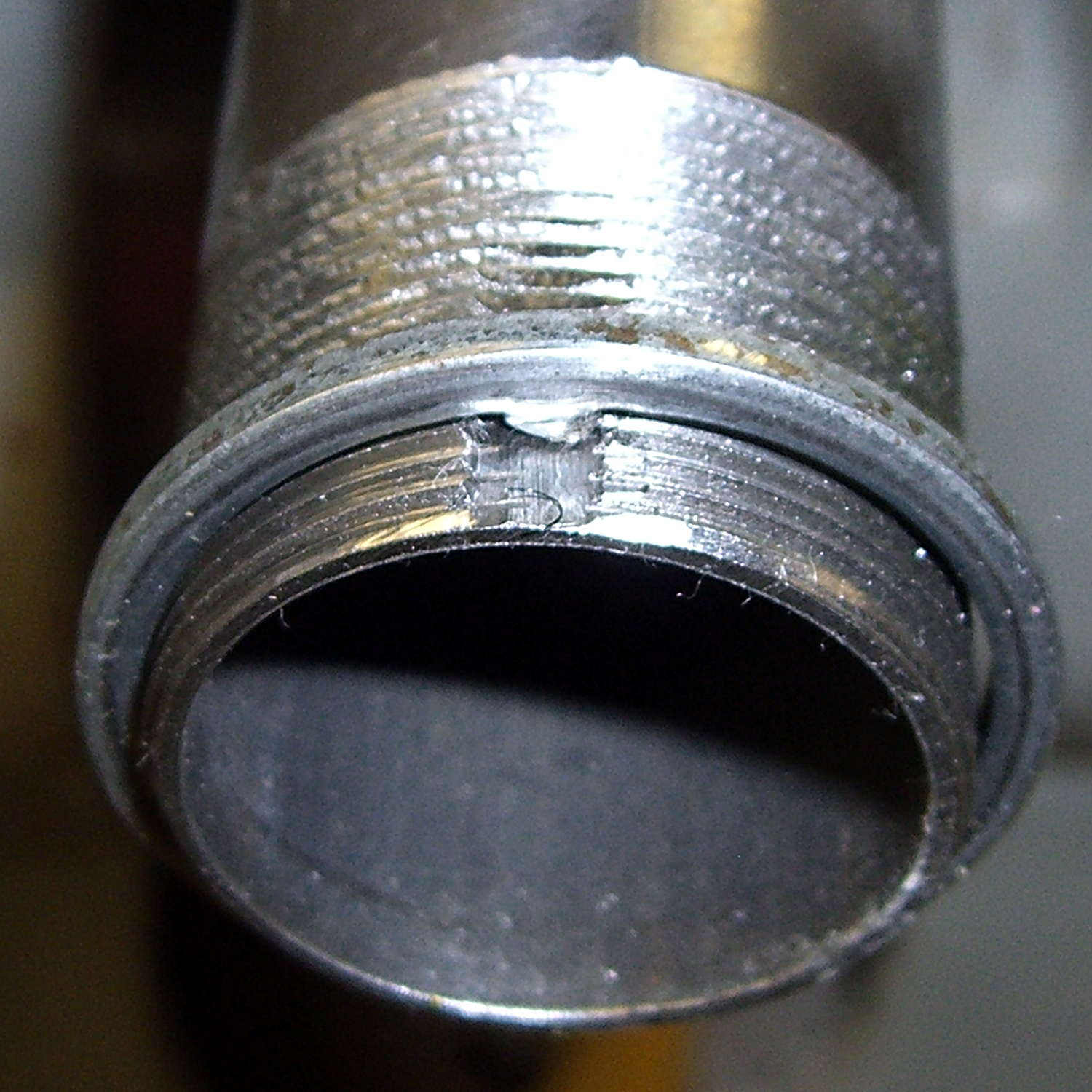
The GE rod continues to corrode nicely:

But, as before, most of the corrosion is close to the top end. The rest of the rod was covered with a thick mineral scale that I hammered off, then scuffed the rod with a shoe rasp to expose some metal.
The Smell of Molten Projects in the Morning
Ed Nisley's Blog: Shop notes, electronics, firmware, machinery, 3D printing, laser cuttery, and curiosities. Contents: 100% human thinking, 0% AI slop.
Mechanical widgetry
The objective being to wrap a nose around the cutter blade to allow some control over the cut depth, I lengthened the cylinder around the cutter body and modeled a discrete glue-on cap:

Which, with an additional 80 g of ballast, worked fine in the double-thick vinyl:

The pen-lift spring can just barely manage to heave that load off the vinyl, but it’s obviously running at the limit of its ability and this can’t possibly be a Good Thing for the mechanism in the long run.
After a bit more fiddling around, I noticed that the stabilizer wasn’t sitting flat on the pen holder and that there really wasn’t any good reason to have a separate cap, so I did one more revision:

The cutaway view shows the knife model now has tapered transition from the body to the grossly enlarged blade, so the model will build without supports inside the cylinder.
A little cutout on one wall lets the plate sit flat on the pen holder and a barely visible recess in the cylinder gives the carousel pen-capping actuator a bit more clearance:

It works about as well as the version shown above, minus the tedious gluing, so I’ll call it a success… even though it’s obviously not going to get much use. I don’t see any way to apply enough downforce to make the cutter work; the mechanical changes just aren’t worthwhile.
The OpenSCAD source code, which includes some tweaks and outright kludges since the first version, builds adapters for Sakura pens (which work just fine) as well as this knife stabilizer:
// HP 7475A plotter pen adapters
// Ed Nisley KE4ZNU April 2015
Layout = "BuildStabilizer";
// ShowBody BuildBody BodyPoly
// ShowPen ShowPenAdapter BuildPenAdapter Plug Pen PenPoly
// ShowKnife BuildKnife KnifeAdapter Knife
// ShowStabilizer Stabilizer BuildStabilizer
//- Extrusion parameters must match reality!
ThreadThick = 0.25;
ThreadWidth = 0.40;
HoleWindage = 0.2;
Protrusion = 0.1; // make holes end cleanly
inch = 25.4;
function IntegerMultiple(Size,Unit) = Unit * ceil(Size / Unit);
//----------------------
// Dimensions
// Z=0 at pen tip!
NumSides = 8*4; // number of sides on each "cylinder"
RADIUS = 0; // subscript for radius values
HEIGHT = 1; // ... height above Z=0
//-- Original HP plotter pen, which now serves as a body for the actual pen
BodyOutline = [ // X values = (measured diameter)/2, Y as distance from tip
[0.0,0.0], // 0 fiber pen tip
// [2.0/2,1.4], // 1 ... taper (not buildable)
[1.0/2,0.005], // 1 ... faked point to remove taper
[2.0/2,0.0],[2.0/2,2.7], // 2 ... cylinder
[3.7/2,2.7],[3.7/2,4.45], // 4 tip surround
[4.8/2,5.2], // 6 chamfer
[6.5/2,11.4], // 7 rubber seal face
[8.9/2,11.4], // 8 cap seat
[11.2/2,15.9], // 9 taper to body
[11.5/2,28.0], // 10 lower body
[13.2/2,28.0],[16.6/2,28.5], // 11 lower flange = 0.5
[16.6/2,29.5],[13.2/2,30.0], // 13 flange rim = 1.0
[11.5/2,30.0], // 15 upper flange = 0.5
[11.5/2,43.25], // 16 upper body
[0.0,43.25] // 17 lid over reservoir
];
TrimHeight = BodyOutline[9][HEIGHT]; // cut off at top of lower taper
SplitHeight = (BodyOutline[11][HEIGHT] + BodyOutline[14][HEIGHT])/2; // middle of flange
FlangeOD = 2*BodyOutline[13][RADIUS];
FlangeTop = BodyOutline[15][HEIGHT];
BodyOD = 2*BodyOutline[16][RADIUS];
BodyOAL = BodyOutline[17][HEIGHT];
echo(str("Trim: ",TrimHeight));
echo(str("Split: ",SplitHeight));
BuildSpace = FlangeOD;
//-- Sakura Micron fiber-point pen
ExpRP = 0.15; // expand critical sections (by radius)
//-- pen locates in holder against end of outer body
PenOutline = [
[0,0], // 0 fiber pen tip
[0.6/2,0.0],[0.6/2,0.9], // 1 ... cylinder
[1.5/2,0.9],[1.5/2,5.3], // 3 tip surround
[4.7/2,5.8], // 5 chamfer
[4.9/2,12.3], // 6 nose
// [8.0/2,12.3],[8.0/2,13.1], // 7 latch ring
// [8.05/2,13.1],[8.25/2,30.5], // 9 actual inner body
[8.4/2 + ExpRP,12.3],[8.4/2 + ExpRP,30.5], // 7 inner body - clear latch ring
[9.5/2 + ExpRP,30.5], // 9 outer body - location surface!
[9.8/2 + ExpRP,50.0], // 10 outer body - length > Body
[7.5/2,50.0], // 11 arbitrary length
[7.5/2,49.0], // 12 end of reservoir
[0,49.0] // 13 fake reservoir
];
PenNose = PenOutline[6];
PenLatch = PenOutline[7];
PenOAL = PenOutline[11][HEIGHT];
//-- Plug for end of cut-off pen body
// you need two plugs...
PlugOutline = [
[0,0], // 0 center of lid
[9.5/2,0.0],[9.5/2,1.0], // 1 lid rim <= body OD
[7.9/2,1.0], // 3 against end of pen
[7.6/2,6.0], // 4 taper inside pen body
[5.3/2,6.0], // 5 against ink reservoir
[4.0/2,1.0], // 6 taper to lid
[0.0,1.0] // 7 flat end of taper
];
PlugOAL = PlugOutline[5][HEIGHT];
// cap locates against end of inner body at latch ring
//-- cap origin is below surface to let pen tip be at Z=0
CapGap = 1.0; // gap to adapter body when attached
CapGripHeight = 2.0; // thickness of cap grip flange
CapTipClearance = 1.0; // clearance under fiber tip
CapOffset = -(CapGripHeight + CapTipClearance); // align inside at pen tip Z=0
CapOutline = [
[0,CapOffset], // 0 base
[FlangeOD/2,CapOffset], // 1 finger grip flange
[FlangeOD/2,CapOffset + CapGripHeight], // 2 ... top
[BodyOD/2,CapOffset + CapGripHeight], // 3 shaft
[BodyOD/2,TrimHeight - CapGap], // 4 ... top with clearance
[PenLatch[RADIUS],TrimHeight - CapGap], // 5 around pen latch ring
[PenLatch[RADIUS],PenNose[HEIGHT]], // 6 ... location surface!
[PenNose[RADIUS] + ExpRP,PenNose[HEIGHT]], // 7 snug around nose
[PenNose[RADIUS] + ExpRP,-CapTipClearance], // 8 clearance around tip
[0,-CapTipClearance], // 9 ... bottom
];
//-- Roland drag knife bearing assembly
ExpRK = 0.30; // expand critical sections (by radius)
AdjLen = 2.0; // allowance for adjustment travel
//- Knife tweaked for pen adapter
/*
KnifeOutline = [
[0,0], // 0 blade point (actually 0.25 mm offset)
[1.0/2,0.0], // 1 ... blunt end
[1.0/2,4.0], // 2 ... cylinder
[2.0/2,4.0], // 3 blade shank
[2.0/2,5.9], // 4 .. at bearing
[6.0/2,5.9], // 5 holder - shell
[7.3/2 + ExpRK,8.3], // 6 holder - taper to body
[7.3/2 + ExpRK,21.0 - AdjLen], // 7 holder body
[8.8/2 + ExpRK,22.0 - AdjLen], // 8 holder - threads bottom
[8.8/2 + ExpRK,25.0],[9.0/2 + ExpRK,26.0], // 9 clear threads to reduce friction
[9.0/2 + ExpRK,32.0],[8.8/2 + ExpRK,33.0], // 11 ... end clearance
[8.8/2 + ExpRK,42.5 - AdjLen], // 13 holder - threads top = locknut bottom
[12.5/2,42.5 - AdjLen], // 14 knurled locknut - adjustment travel
[12.5/2,45.8], // 15 knurled locknut - top
[11.0/2,45.8], // 16 holder - adjusting knurl
[11.0/2,52.0], // 17 holder - top surface
[3.0/2,52.0],[3.0/2,57.2], // 18 spring post
[0.0,57.2] // 19 end of post
];
*/
//- Knife tweaked for stabilizer
KnifeOutline = [
[0,0], // 0 blade point (actually 0.25 mm offset)
[3.0/2,0.0], // 1 ... blunt end
[3.0/2,4.0], // 2 ... cylinder
[3.0/2,4.0], // 3 blade shank
[6.0/2,5.9], // 4 .. at bearing (taper to support nose)
[6.0/2,5.9], // 5 holder - shell
[7.3/2 + ExpRK,8.3], // 6 holder - taper to clear threads
[7.3/2 + ExpRK,21.0 - AdjLen], // 7 ..
[8.8/2 + ExpRK,22.0 - AdjLen], // 8 holder - threads bottom
[8.8/2 + ExpRK,25.0],[9.0/2 + ExpRK,26.0], // 9 clear threads to reduce friction
[9.0/2 + ExpRK,32.0],[8.8/2 + ExpRK,33.0], // 11 ... end clearance
[8.8/2 + ExpRK,42.5 - AdjLen], // 13 holder - threads top = locknut bottom
[12.5/2,42.5 - AdjLen], // 14 knurled locknut - adjustment travel
[12.5/2,45.8], // 15 knurled locknut - top
[11.0/2,45.8], // 16 holder - adjusting knurl
[11.0/2,52.0], // 17 holder - top surface
[3.0/2,52.0],[3.0/2,57.2], // 18 spring post
[0.0,57.2] // 19 end of post
];
ThreadStart = KnifeOutline[8][HEIGHT];
ThreadOD = 2*KnifeOutline[11][RADIUS];
//-- Plotter pen holder stabilizer
HolderPlateThick = 3.0; // thickness of plate atop holder
RimHeight = 5.0; // rim around sides of holder
RimThick = 2.0; // wall thickness
HolderOrigin = [17.0,12.2,0.0]; // center of pen tip relative to polygon coordinates
HolderHeight = 30.0; // top of holder to platen in pen-down position
HolderTopThick = 1.7; // top of holder to top of pen flange
HolderNoseLength = 4.0; // length of nose taper
HolderKnifeOffset = -3.0; // additional downward adjustment range
LockScrewInset = 3.0; // from right edge of holder plate
LockScrewOD = 2.0; // tap for 2.5 mm screw
UncapperHeight = -17.0; // uncapping actuator arm from top of pen holder
UncapperOD = 11.0; // ... max OD that clears uncapper
// Beware: update hardcoded subscripts in Stabilizer() when adding / deleting point entries
HolderPlate = [
[8.6,18.2],[8.6,23.9], // 0 lower left corner of pen recess
[13.9,23.9],[13.9,30.0], // 2
// [15.5,30.0],[15.5,25.0], // 4 omit middle of support beam
// [20.4,25.0],[20.4,30.0], // 6
[22.7,30.0],[22.7,27.5], // 4
[35.8,27.5],[35.8,20.7], // 6 spring box corner
[43.0,20.7], // 8
[31.5,0.0], // 9
// [24.5,0.0],[24.5,8.0], // 10 omit pocket above pen clamp
// [22.5,10.0],[22.5,16.5], // 12
// [20.5,18.2] // 14
[13.6,0.0], // 10
[8.6,5.0] // 11
];
BeamWidth = HolderPlate[4][0] - HolderPlate[2][0]; // rear support beam
TabWidth = HolderPlate[1][1] - HolderPlate[0][1]; // tab extending left beyond pen recess
TabClear = 3.0; // maximum rim height over tab
HolderCylinderOutline = [
[0,0], // 0 center of nose
[6.0/2,0.0], // 1 flat nose surface OD
[BodyOD/2,HolderNoseLength], // 2 taper to cylinder OD
[BodyOD/2,HolderHeight], // 3 cylinder to top of holder plate
[0,HolderHeight] // 4 flat top
];
//----------------------
// Useful routines
module PolyCyl(Dia,Height,ForceSides=0) { // based on nophead's polyholes
Sides = (ForceSides != 0) ? ForceSides : (ceil(Dia) + 2);
FixDia = Dia / cos(180/Sides);
cylinder(r=(FixDia + HoleWindage)/2,
h=Height,
$fn=Sides);
}
//- Locating pin hole with glue recess
// Default length is two pin diameters on each side of the split
PinOD = 1.75;
PinOC = BodyOD / 2;
module LocatingPin(Dia=PinOD,Len=0.0) {
PinLen = (Len != 0.0) ? Len : (4*Dia);
translate([0,0,-ThreadThick])
PolyCyl((Dia + 2*ThreadWidth),2*ThreadThick,4);
translate([0,0,-2*ThreadThick])
PolyCyl((Dia + 1*ThreadWidth),4*ThreadThick,4);
translate([0,0,-(Len/2 + ThreadThick)])
PolyCyl(Dia,(Len + 2*ThreadThick),4);
}
module LocatingPins(Length) {
for (i=[-1,1])
translate([0,i*PinOC/2,0])
rotate(180/4)
LocatingPin(Len=Length);
}
//----------------------
// Basic shapes
//-- HP plotter pen body
module ShowPolygon(pts) {
polygon(pts);
}
module Body() {
render(convexity=3)
rotate_extrude($fn=NumSides)
polygon(points=BodyOutline);
}
//-- Sakura drawing pen body
module Pen() {
rotate_extrude($fn=NumSides)
polygon(points=PenOutline);
}
//-- Plug for top of Sakura pen
module Plug() {
render(convexity = 2)
rotate_extrude($fn=NumSides)
polygon(points=PlugOutline);
}
//-- Cap for tip of Sakura pen
module Cap() {
render(convexity = 2)
rotate_extrude($fn=NumSides)
polygon(points=CapOutline);
}
//-- Sakura pen adapter
module PenAdapter() {
render(convexity=3)
difference() {
Body();
Pen();
translate([0,0,TrimHeight/2])
cube([2*FlangeOD,2*FlangeOD,TrimHeight],center=true);
}
}
//-- Roland knife body
module Knife() {
render(convexity=3)
rotate_extrude($fn=NumSides)
polygon(points=KnifeOutline);
}
//-- Roland knife adapter
module KnifeAdapter(TrimZ = false) {
Trans = TrimZ ? - TrimHeight : 0;
render(convexity=5)
translate([0,0,Trans])
difference() {
Body();
Knife();
translate([0,0,TrimHeight/2])
cube([2*FlangeOD,2*FlangeOD,TrimHeight],center=true);
}
}
//-- nose cap for stabilizer cylinder
module StabilizerNose() {
render(convexity = 2)
rotate_extrude($fn=NumSides)
polygon(points=StabilizerNoseOutline);
}
//-- Roland knife stabilizer atop pen holder
// the trim blocks have offsets with magic numbers from the HolderPlate outline &c
module Stabilizer(SeeKnife = false) {
Cutout = (Layout == "ShowStabilizer") ? 0 : 1;
difference() {
union() {
translate(-HolderOrigin) // put center of pen at origin
translate([0,0,-RimHeight]) // put top of holder at Z=0
difference() {
render(convexity=4)
linear_extrude(height=(HolderPlateThick + RimHeight)) // overall flange around edges
offset(r=RimThick)
polygon(points=HolderPlate);
render(convexity=4)
translate([0,0,-Protrusion]) // recess for pen holder plate
linear_extrude(height=(RimHeight + Protrusion))
polygon(points=HolderPlate);
translate([HolderPlate[7][0] - Protrusion,HolderPlate[7][1] - Protrusion,-Protrusion]) // trim spring box from top plate
cube([30,20,(RimHeight + HolderPlateThick + 2*Protrusion)]);
translate([27.0,HolderPlate[6][1] - Protrusion,-Protrusion]) // trim pivot plate clearance
cube([30,20,(RimHeight + HolderPlateThick + 2*Protrusion)]);
translate([HolderPlate[2][0],20,-Protrusion]) // trim left support beam
cube([BeamWidth,20,(RimHeight + Protrusion)]);
translate([0,HolderPlate[0][1],-(TabClear + Protrusion)]) // trim tab behind pen recess
cube([(HolderPlate[0][0] + Protrusion),TabWidth,RimHeight + Protrusion]);
translate([HolderPlate[9][0] - LockScrewInset,RimThick,RimHeight - HolderTopThick - LockScrewOD/2]) // lock screw on front edge
rotate([90,0,0])
rotate(180/4)
PolyCyl(LockScrewOD,3*RimThick); // punch out hold-down screw hole
}
difference() {
translate([0,0,-HolderHeight]) // cylinder and nose
rotate_extrude($fn=NumSides)
polygon(points=HolderCylinderOutline);
translate([-HolderOrigin[0],-(BodyOD + Cutout*UncapperOD/2),(UncapperHeight - HolderHeight)]) // uncapper clearance
cube([2*HolderOrigin[0],BodyOD,HolderHeight]);
}
}
translate([0,0,-HolderHeight + HolderKnifeOffset])
if (SeeKnife)
# Knife();
else
Knife();
}
}
//----------------------
// Build it
if (Layout == "Pen")
Pen();
if (Layout == "Knife")
Knife();
if (Layout == "Stabilizer")
Stabilizer();
if (Layout == "ShowBody")
Body();
if (Layout == "BodyPoly") {
ShowPolygon(BodyOutline);
Body();
}
if (Layout == "PenPoly") {
ShowPolygon(PenOutline);
Pen();
}
if (Layout == "BuildBody") {
Spacing = 0.75*BuildSpace;
difference() {
union() {
translate([Spacing,0,-SplitHeight])
Body();
rotate([180,0,0])
translate([-Spacing,0,-SplitHeight])
Body();
}
translate([0,0,-BodyOAL])
cube(2*BodyOAL,center=true);
for (i = [-1,1])
translate([i*Spacing,0,0])
LocatingPins(5.0);
}
}
if (Layout == "Plug")
Plug();
if (Layout == "KnifeAdapter")
KnifeAdapter();
if (Layout == "ShowPen") {
color("AntiqueWhite") {
Pen();
translate([-1.5*BodyOD,0,0])
Pen();
}
color("Magenta",0.35) {
translate([0,0,PlugOAL + PenOAL + 3.0])
rotate([180,0,0])
Plug();
PenAdapter();
Cap();
}
color("Magenta") {
translate([1.5*BodyOD,0,PlugOAL + PenOAL + 3.0])
rotate([180,0,0])
Plug();
translate([1.5*BodyOD,0,0]) {
PenAdapter();
Cap();
}
}
}
if (Layout == "ShowPenAdapter") {
color("AntiqueWhite") {
translate([0.00*BodyOD,0,0])
Pen();
translate([-2.75*BodyOD,0,0])
Pen();
}
translate([-1.50*BodyOD,0,0])
color("SandyBrown")
Body();
translate([0.00*BodyOD,0,0])
color("SandyBrown",0.35)
PenAdapter();
translate([3.00*BodyOD,0,0])
color("SandyBrown")
PenAdapter();
translate([1.50*BodyOD,0,0])
difference() {
color("SandyBrown")
PenAdapter();
translate([-BodyOD,-2*BodyOD,0])
cube([2*BodyOD,2*BodyOD,PenOAL]);
}
}
if (Layout == "ShowKnife") {
color("Goldenrod") {
Knife();
translate([-1.5*BodyOD,0,0])
Knife();
}
color("Magenta",0.35)
KnifeAdapter();
color("Magenta") {
translate([1.5*BodyOD,0,0])
KnifeAdapter();
}
}
if (Layout == "BuildPenAdapter") {
if (false) {
for (j = [-1,1])
translate([j*BuildSpace/2,-0.7*BuildSpace,0])
Plug();
translate([0,0,-CapOffset])
Cap();
}
else {
Plug();
}
difference() {
union() {
translate([1.20*BuildSpace,0,-SplitHeight])
PenAdapter();
rotate([180,0,0])
translate([-1.20*BuildSpace,0,-SplitHeight])
PenAdapter();
}
translate([0,0,-BodyOAL])
cube(2*BodyOAL,center=true);
}
}
if (Layout == "BuildKnife") {
difference() {
union() {
translate([0.7*BuildSpace,0,-SplitHeight])
KnifeAdapter(false);
rotate([180,0,0])
translate([-0.7*BuildSpace,0,-SplitHeight])
KnifeAdapter(false);
}
translate([0,0,-BodyOAL])
cube(2*BodyOAL,center=true);
}
}
if (Layout == "BuildStabilizer") {
translate([0,0,HolderPlateThick])
rotate([0,180,0])
Stabilizer(false);
}
if (Layout == "ShowStabilizer") {
translate([BuildSpace/2,0,HolderHeight])
Stabilizer(true);
translate([-BuildSpace/2,0,HolderKnifeOffset])
Knife();
}
Well, with a bit of ballast, that little unsupported blade actually did cut some vinyl:

That ugly nut adds 125 g to the pen holder’s 19±10 g (that’s the spec) down force and grossly overloads the pen-lift spring at the solenoid, but it did provide enough force to carve that little strip from the vinyl sheet. Vertical compliance comes from the pen holder’s travel, so the weight exerts a constant force at the knife tip.
I’m using the front-panel controls to drive the pen around at whatever speed the FAST button provides, which limits the results to straight lines.
The vinyl, leftover from a discarded window decoration, is 0.15 mm = 6 mil thick and definitely not intended for use with a cutter; vinyl cutter sheets and rolls seem to run around 0.07 mm = 3 mil.
Obviously, this doesn’t have much potential, but it actually worked better than I expected. The unguarded blade bites into the substrate (which I did expect), so the next step is to wrap a nose around the blade for controlled depth-of-cut.
Somewhat encouraged by the results of the height-map cap atop the plotter’s pen holder, I figured a unified knife adapter and stabilizer cap would work even better. That requires enough accuracy to build a real solid model, rather than just sketch a height map…
Print out the the grid-overlaid image of the pen holder, then doodle coordinates & measurements all over the poor thing:

Now I can toss that piece of paper…
That, plus a bit of digital caliper work, produces a flurry of dimensions & an array of vertices:
//-- Plotter pen holder stabilizer HolderPlateThick = 3.0; // thickness of plate atop holder RimHeight = 5.0; // rim around sides of holder RimThick = 2.0; HolderOrigin = [17.0,12.2,0.0]; // center of pen relative to polygon coordinates HolderZOffset = 30.0; // top of holder in pen-down position HolderTopThick = 1.7; // top of holder to top of pen flange HolderCylinderLength = 17.0; // length of pen support structure HolderKnifeOffset = -2.0; // additional downward adjustment range (not below top surface) LockScrewInset = 3.0; // from right edge of holder plate LockScrewOD = 2.0; // tap for 2.5 mm screw // Beware: update hardcoded subscripts in Stabilizer() when adding / deleting point entries HolderPlate = [ [8.6,18.2],[8.6,23.9], // 0 lower left corner of pen recess [13.9,23.9],[13.9,30.0], // 2 // [15.5,30.0],[15.5,25.0], // 4 omit middle of support beam // [20.4,25.0],[20.4,30.0], // 6 [22.7,30.0],[22.7,27.5], // 4 [35.8,27.5],[35.8,20.7], // 6 spring box corner [43.0,20.7], // 8 [31.5,0.0], // 9 // [24.5,0.0],[24.5,8.0], // 10 omit pocket above pen clamp // [22.5,10.0],[22.5,16.5], // 12 // [20.5,18.2] // 14 [13.6,0.0], // 10 [8.6,5.0] // 11 ]; BeamWidth = HolderPlate[4][0] - HolderPlate[2][0];
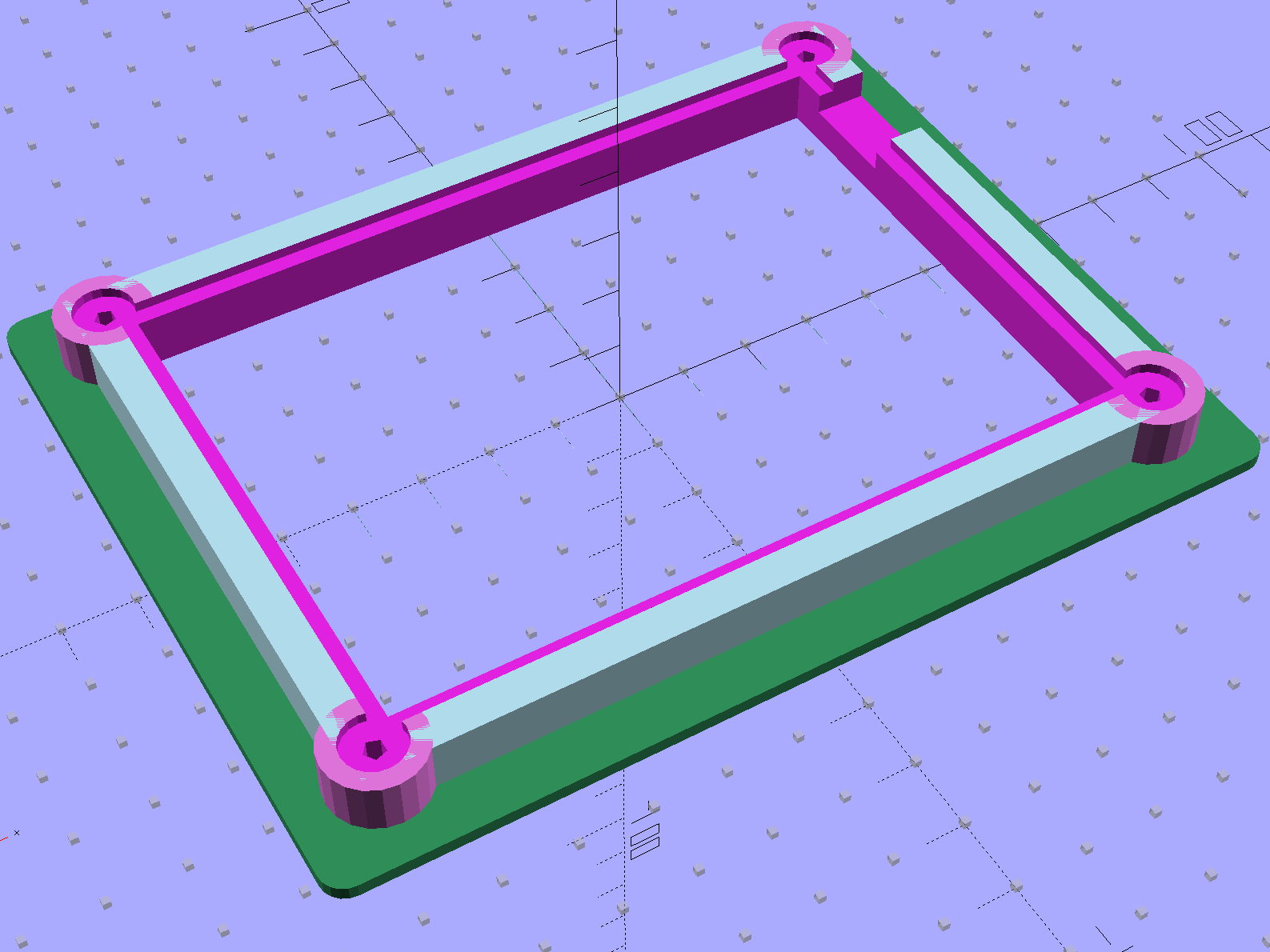
The general idea is to extrude the overall shape of the stabilizer cap, carve out chunks to fit it onto the pen holder, then add a cylinder around the knife bearing:

The OpenSCAD source code contains a bunch of magic numbers and indexes that pull values from the vertex array:
module Stabilizer(SeeKnife = false) {
difference() {
union() {
translate(-HolderOrigin) // put center of pen at origin
difference() {
render(convexity=4)
linear_extrude(height=(HolderPlateThick + RimHeight)) // overall flange around edges
offset(r=RimThick)
polygon(points=HolderPlate);
render(convexity=4)
translate([0,0,-Protrusion]) // recess for pen holder plate
linear_extrude(height=(RimHeight + Protrusion))
polygon(points=HolderPlate);
translate([HolderPlate[7][0] - Protrusion,HolderPlate[7][1] - Protrusion,-Protrusion]) // trim spring box from top plate
cube([30,20,(RimHeight + HolderPlateThick + 2*Protrusion)]);
translate([27.0,HolderPlate[6][1] - Protrusion,-Protrusion]) // trim pivot plate clearance
cube([30,20,(RimHeight + HolderPlateThick + 2*Protrusion)]);
translate([HolderPlate[2][0],20,-Protrusion]) // trim left support beam
cube([BeamWidth,20,(RimHeight + Protrusion)]);
translate([HolderPlate[9][0] - LockScrewInset,RimThick,RimHeight - HolderTopThick - LockScrewOD/2]) // lock screw on front edge
rotate([90,0,0])
rotate(180/4)
PolyCyl(LockScrewOD,3*RimThick); // hold-down screw hole
}
translate([0,0,(RimHeight - HolderCylinderLength + Protrusion)])
cylinder(d=BodyOD,h=HolderCylinderLength + Protrusion,$fn=NumSides); // surround knife threads
}
translate([0,0,-HolderZOffset + HolderKnifeOffset])
if (SeeKnife)
# Knife();
else
Knife();
}
}
A bottom view shows all the cutouts:

The little hole in the front fits a screw that will pass under the top plate of the pen holder and prevent the cutting forces from pushing it off.
As with the Sakura pen adapter, the knife point sits at (0,0,0) with the stabilizer cap positioned at the (estimated) top of the pen holder:

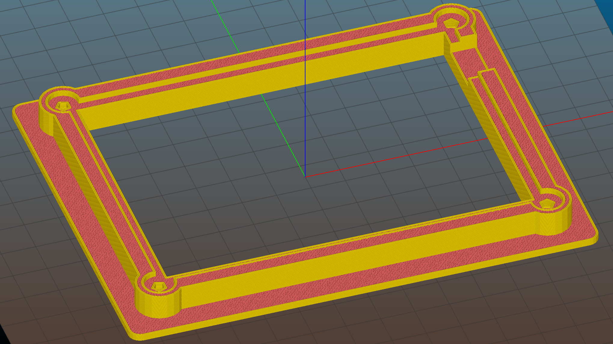
After a few print-and-try iterations to align all the fiddly cutouts:

The slope-topped block protruding toward you from the bottom right actuates the carousel’s pen capping mechanism; it doesn’t quite touch the side of an HP pen and is well clear of the knife holder.
Because there’s still no depth control surrounding the knife blade, this won’t work well at all, but it should suffice for better measurements.
The full source code is back at the beginning.
The “pen holder” in an HP 7475A plotter carries the pen across the width of the paper:

Given that it was designed to carry pens, not knives, I wasn’t surprised that the spring-loaded finger clamping the knife adapter didn’t apply enough force to hold the adapter in place against the cutting forces. I figured a quick test of a gizmo to stabilize the adapter would be in order, even though I knew:
In order to build the gizmo, I need the carrier’s dimensions…
An overhead photo of the pen holder shows the layout in the XY plane:

I shouldn’t have used graph paper as a background, because the next step was to remove the background and isolate the carrier:

The carrier measures 26.8 mm front-to-back, so scaling a grid to match that dimension provides a coordinate system overlay:

The (0,0) origin sits at the lower left, so you can read off all the relevant coordinates as needed.
However, rather than go full-frontal digital, I resized the isolated image to 20 pixel/mm, turned it into a height map, and treated it like a chocolate mold or cookie cutter with gray values scaled to the desired height:
Drawing the walls with a 40 pixel diameter pen makes them 2 mm wide at 20 pixel/mm:

It’s painfully obvious why I don’t do much freehand drawing, although the knife adapter hole is supposed to be oval.
As with cookie cutters and chocolate molds, there’s no need for that much resolution, so I rescaled it to 4 pixel/mm, saved that tiny image as a PNG file, and handed it to OpenSCAD’s surface() function to get a solid model. This being a one-off, I typed this OpenSCAD source code directly into the OpenSCAD editor on the fly, then remembered to save it (!) before shutting down:
rotate([0,180,0])
mirror([0,0,1])
scale([0.25,0.25,10/100])
difference() {
translate([0,0,-2.0]) render(convexity=10)
surface("/long-and-tedious-path/HP7475A - knife stabilizer - scaled.png",center=true);
translate([0,0,-200])
cube(400,center=true);
}
The mirror() transformation inverts the model top-to-bottom along the Z axis, compensating for the flip from drawing the height map as though the walls rise upward from the pen carrier, after which the flip() transformation puts the flat side down to make it buildable.
The height map image conversion produces a bazillion irrelevant faces, but it’s quick and easy:

I’ve been using Slic3r’s Hilbert Curve pattern for top & bottom infill to get a nice textured result:

Which printed just about like you’d expect:

I reamed out the hole with a step drill (the HP pens are close enough to 7/16 as to make no difference here) to get the knife adapter to fit, but the walls and suchlike came out close enough.
Then it just snapped into place:

Actually, no, it didn’t just snap into place: some (dis)assembly was required.
First, remove the brass knife bearing from the adapter, push the knife adapter shell into the pen holder, slide the stabilizer cap down over the adapter, press it firmly around the pen holder, reinstall the brass knife bearing, then it’s ready.
The cuts in the green vinyl just to the left of the knife blade (in a window decoration sheet I spotted in a trash can) show that the blade can cut, albeit with some finger pressure, but the fancy red stabilizer didn’t stay stuck on the pen carrier nearly as well as I expected. A screw attachment will help with that, which calls for going all digital on those coordinates.
But it was quick & easy…
Knockoff Roland drag knife blades and holders being cheap and readily available on eBay, it didn’t take long to figure out that they’re not drop-in replacements for HP pens:

The Roland Cutter Knowledge PDF shows that the blade must protrude just slightly beyond the holder shell, letting the flat end stabilize the media and regulate the cut depth, but some experimentation was in order just to get the mechanics worked out.
The central brass blade holder looks like it should fit neatly inside the pen body outline:

A small O-ring normally fits in the thread gap to provide some friction between the two metal parts, with the knurled nut locking them together at the desired setting.
The blade rides on a smooth bearing pushed upward against a stop by a spring exerting 220-400 g on that rounded shaft. I think a real vinyl cutter would have a spring-loaded pin pushing downward on that shaft to provide vertical compliance at the blade tip, but I’ve never seen such a thing in real life.
That suggests half a pound of downward cutter force that the HP pen holder definitely can’t provide; the spec is 19±10 g.
Applying a digital caliper to the blade holder produced the usual measurement array:
//-- Drag knife holder ExpRK = 0.30; // expand critical sections (by radius) AdjLen = 2.0; // allowance for adjustment travel KnifeOutline = [ [0,0], // 0 blade point (actually 0.25 mm offset) [1.0/2,0.0], // 1 ... blunt end [1.0/2,4.0], // 2 ... cylinder [2.0/2,4.0], // 3 shank [2.0/2,5.9], // 4 .. at bearing [6.0/2,5.9], // 5 holder - shell [7.3/2 + ExpRK,8.3], // 6 holder - taper to body [7.3/2 + ExpRK,21.0 - AdjLen], // 7 holder body [8.8/2 + ExpRK,22.0 - AdjLen], // 8 holder - threads bottom [8.8/2 + ExpRK,25.0],[9.0/2 + ExpRK,26.0], // 9 clear threads to reduce friction [9.0/2 + ExpRK,32.0],[8.8/2 + ExpRK,33.0], // 11 ... end clearance [8.8/2 + ExpRK,42.5 - AdjLen], // 13 holder - threads top = locknut bottom [12.5/2,42.5 - AdjLen], // 14 knurled locknut - adjustment travel [12.5/2,45.8], // 15 knurled locknut - top [11.0/2,45.8], // 16 holder - adjusting knurl [11.0/2,52.0], // 17 holder - top surface [3.0/2,52.0],[3.0/2,57.2], // 18 spring post [0.0,57.2] // 19 end of post ]; ThreadLength = KnifeOutline[13][HEIGHT] - KnifeOutline[8][HEIGHT];
Which spins up into a solid model of the brass part:

The large ring is slightly larger than the actual knurled nut, to ensure it cuts off the top of the HP pen body.
The raised section in the middle of the threads provides a little relief, as screwing the holder into a sufficiently snug plastic sleeve turned out to require more effort than seemed reasonable. I don’t have a tap for what might be a loose 9×0.75 mm fine-pitch thread (the actual OD is 8.75), so it’s gotta form its own path.
Subtracting the holder from the HP pen body produced an adapter much like the Sakura pen adapters:

Split across the flange for building:

Running the plotter in Etch A Sketch mode, that little blade actually cut a sheet of paper:

However, it didn’t cut very well at all, mostly because the pen holder doesn’t grip the adapter tightly enough to resist the lateral forces required to drive the blade through the paper, nor does it provide enough downward force to maintain the cut; I cheated by pressing on the holder to encourage the blade to keep on cutting.
By design, the plotter pen lift / drop mechanism doesn’t (and really can’t) apply enough downward force. A sliding bar across the entire width of the plotter raises the holder through a mechanical tab and lowers the holder by releasing the tab. A small spring then provides all the downward force, overcoming a dashpot that slows the pen drop to prevent crushing the nib against the paper.
Just for fun, though, I figured I should see what happens with the blade firmly anchored in the pen holder…
The HP 7475A plotter comes with a transparent smoke-brown plastic flip-up lid covering the carousel and pen holder, presumably to keep dust and fingers out of the moving parts. That lid also has has the side effect of limiting the pen length, presumably because HP didn’t want the 7475A to eat into their large-format plotter market. In any event, removing the lid leaves another barrier to longer pens: the rugged plastic case between the carousel and the pen holder.
Well, seeing as how this puppy has been fully depreciated, a bit of pull saw work opened that opportunity:

Despite appearances, all six Sakura Micron pens emerge vertical & parallel from their adapters in the carousel:

They pass neatly through the new channel:

And produce reasonable lines, with motion blur catching the pen holder in the midst of a pen-up / pen-down twitch:

That’s from an earlier test, before I sawed the slot in the case, with all the machinery behind the pen holder in full view.
The test plot, with the proper pen colors and widths loaded in the carousel, looks pretty good:

The pen holder wasn’t intended to support a long pen, so that shaft tends to torque the pen tip out of position, particularly while drawing characters:

The various pen tips don’t all point to the same place:

That could be non-concentric pen adapters, misalignment in the pen holder, or slightly off-center pen nibs. The offsets between the colors remains consistent in all the bar-chart columns, so the pen adapters aren’t shifting in the holder.
The worst-case error between bar-chart rectangles amounts to 0.5 mm parallel to the pen holder motion and 0.8 mm parallel to the paper motion. In round numbers, the pen tip is 30 mm from the flange, so moving it 0.5 mm to the side tips the pen 1°. The flange is 17 mm OD, which means a 1° tilt raises one edge by 0.3 mm or both edges by ±0.15 mm. Given a 0.25 mm 3D printed thread thickness, that’s certainly within reach of a random plastic blob.
Looking closely at the printed-and-glued flange shows plenty of room for misunderstanding betwixt pen and holder, even after cleaning off all that PETG hair:

Given that the Sakura pens aren’t intended for this application, a slight tip misalignment due to body molding tolerances isn’t unreasonable; a perfect adapter might not solve the problem.
The HP maintenance manual lists a BASIC program to produce a test plot that verifies pen alignment, although the prospect of transliterating 2+ pages of quoted strings from a scanned document doesn’t fill me with desire.