Ed Nisley's Blog: Shop notes, electronics, firmware, machinery, 3D printing, laser cuttery, and curiosities. Contents: 100% human thinking, 0% AI slop.
Imagine “updating” these windows with modern high-efficiency glass:
Terwilliger House – parallelogram windows
That’s the end wall of the 1738 Terwilliger House on the Locust Lawn site. I’m sure the woodwork doesn’t date back that far, but the glazier demonstrated genius-level mastery.
We were on a fascinating behind-the-scenes tour, marred by a visitor who knew the rules about not touching the exhibits didn’t apply to her. My parents ran a restaurant / gift shop and, to this day, my hands automatically find their way into my pockets when I enter a store, let alone a museum.
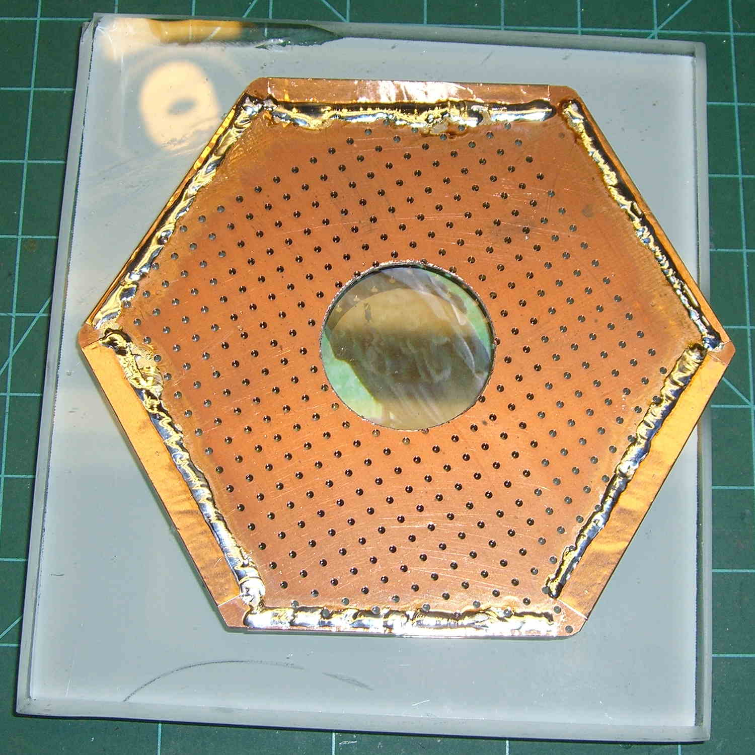
Just to have something to work with, I cut a hex from a sheet of double-sided PCB stock and bonded the edges with copper foil:
Victoreen 710-104 – Hex PCB – top
Slightly wider tape on three edges will clear the board supports:
Victoreen 710-104 – Hex PCB – bottom
For unknown reasons, the PCB has arrays of plated-through holes firmly bonding the top and bottom copper, so that’s pretty much solid copper with a glass-epoxy core. I think somebody (else) harvested it from a locally important company many, many decades ago, but it arrived with no provenance.
The first pass at the electrometer circuitry will be air-wired for low leakage, which is pretty much the only way I have to actually get low leakage; the holes should help glue the parts to that copper plane.
I’m not at all convinced the big hole in the middle is strictly necessary. The chamber has 10 pF from pin to can that should swamp any stray capacitance unless I do something really stupid.
Given my weak origami-fu and the need for hexagonality, I should print a 3D template.
It’s worth remembering that both the hex and the shield will be at the can’s +24 V potential, not “ground”. That makes no difference to the external circuitry, but will certainly cause me to blow a few junctions along the way.
The general idea is to put the electrometer circuitry directly atop the Victoreen 710-104 ionization chamber, so as to minimize the distance from the center collector electrode to the electrometer input. After a few false starts, this looked promising:
Victoreen 710-104 Ionization Chamber Fittings – Show layout
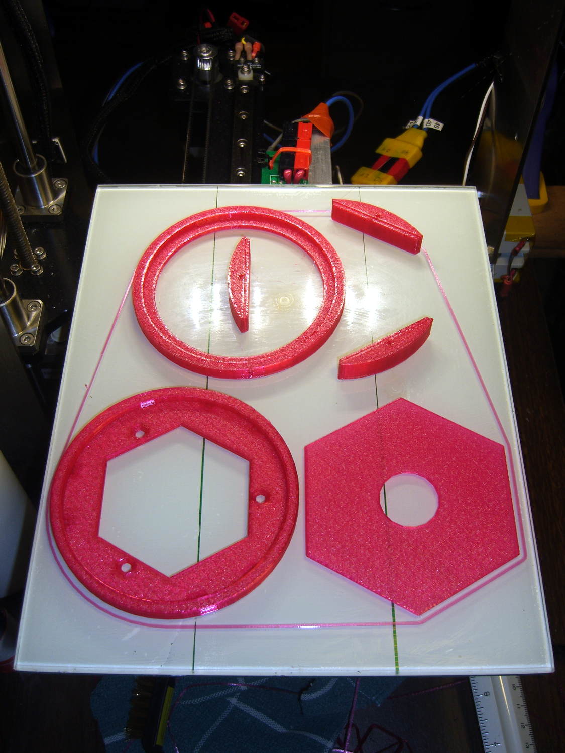
The hexagonal circuit board fits the can so nicely that I’ll run with it, despite the over-the-top twee factor. Because it’s so hard to freehand a hex, I printed the green object as a tracing template, despite having the Slic3r preview show the parts just barely fitting on the M2 platform:
The skirt measures 0.25±0.05 around the entire perimeter, with a slight positive bias (platform too low) along the left side and a corresponding negative bias on the right. Both sides look just fine to me.
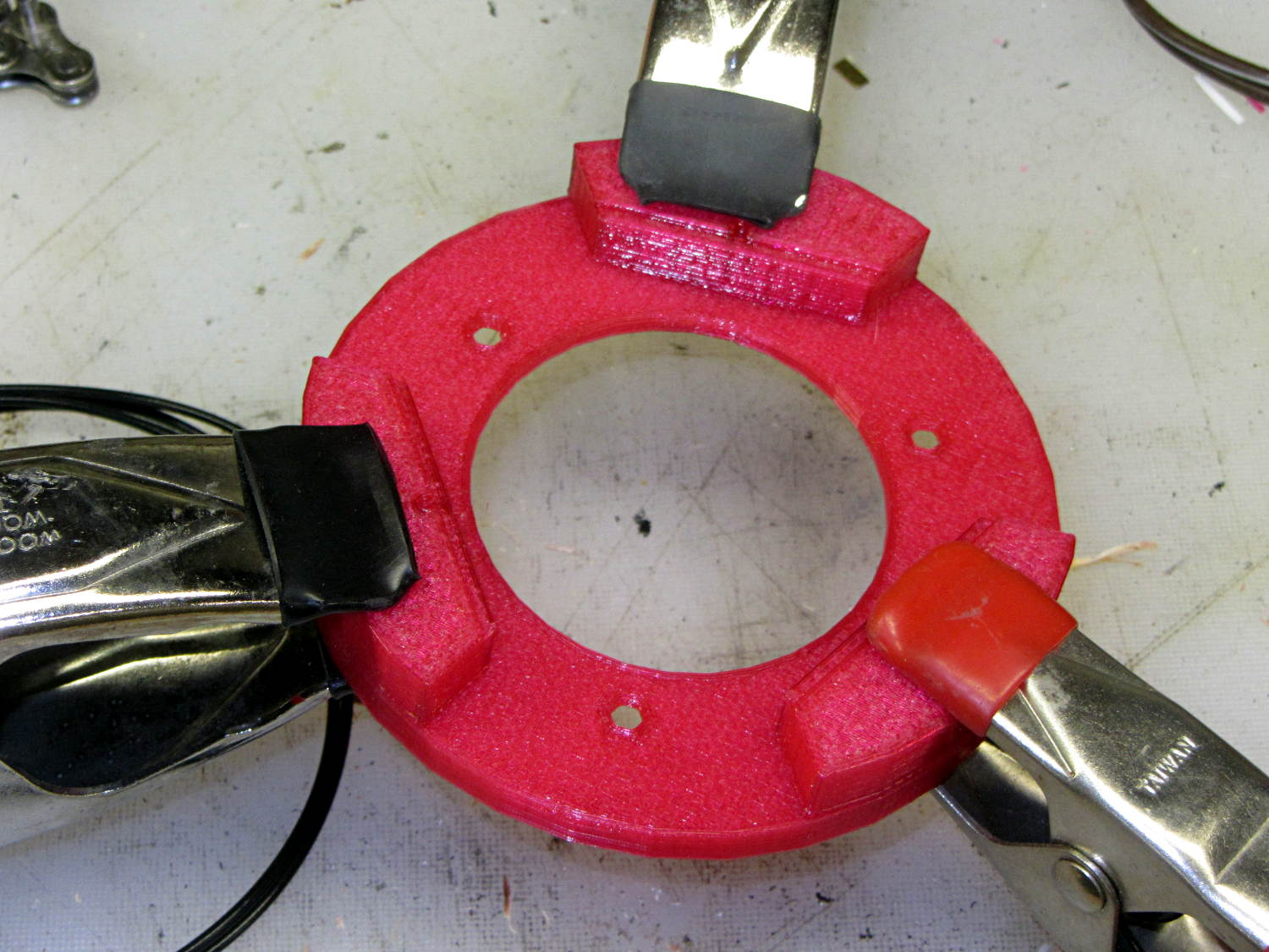
A pair of alignment pegs hold each board support in place while gluing:
Victoreen 710-104 Fittings – clamping
Next time around, I’ll glue the supports with the circuit board template laid in place to ensure the edges have the proper orientation, but they came out surprisingly close just by matching the outer perimeters. Of course, I probably bandsawed / belt sanded the carefully traced hex just slightly off-kilter.
The outer perimeter has 48 sides. Making it a multiple of three means each board support has the same pattern of sides and all will be interchangeable. Making it a multiple of four means each quadrant has the same pattern of sides and the ring looks pleasingly symmetrical. The factor-of-three is most important: you want interchangeable supports. Trust me on this.
The bottom ring keeps the solder dimple that seals the can base off the desk, but I also stuck a quartet of rubber feet on the can for better traction.
Here’s what it looks like with the two A23 12 V bias batteries in their holders, affixed to the can with foam tape:
Victoreen 710-104 Fittings – assembled
The OpenSCAD source code includes a few more tweaks:
// Victoreen 710-104 Ionization Chamber Fittings
// Ed Nisley KE4ZNU July 2015

Layout = "Show";
					// Show - assembled parts
					// Build - print them out!
					// CanCap - PCB insulator for 6-32 mounting studs
					// CanBase - surrounding foot for ionization chamber
					// CanLid - generic surround for either end of chamber
					// PCB - template for cutting PCB sheet
					// PCBBase - holder for PCB atop CanCap

BuildTemplate = false;			// true to build PCB template along with everything else

//- Extrusion parameters must match reality!
//  Print with 2 shells and 3 solid layers

ThreadThick = 0.25;
ThreadWidth = 0.40;

HoleWindage = 0.2;

Protrusion = 0.1;			// make holes end cleanly

AlignPinOD = 1.75;			// assembly alignment pins = filament dia

inch = 25.4;

function IntegerMultiple(Size,Unit) = Unit * ceil(Size / Unit);

//- Screw sizes

Tap4_40 = 0.089 * inch;
Clear4_40 = 0.110 * inch;
Head4_40 = 0.211 * inch;
Head4_40Thick = 0.065 * inch;
Nut4_40Dia = 0.228 * inch;
Nut4_40Thick = 0.086 * inch;
Washer4_40OD = 0.270 * inch;
Washer4_40ID = 0.123 * inch;


//----------------------
// Dimensions

OD = 0;											// name the subscripts
LENGTH = 1;

Chamber = [91.0 + HoleWindage,38];				// Victoreen ionization chamber dimensions

Stud = [										// stud welded to ionization chamber lid
	[6.5,IntegerMultiple(0.8,ThreadThick)],		// flat head -- generous clearance
	[4.0,9.5],									// 6-32 screw -- ditto
];
NumStuds = 3;
StudSides = 6;									// for hole around stud

BCD = 2.75 * inch;								// mounting stud bolt circle diameter

PlateThick = 3.0;								// layer atop and below chamber ends
RimHeight = 4.0;								// extending up along chamber perimeter
WallHeight = RimHeight + PlateThick;
WallThick = 5.0;								// thick enough to be sturdy & printable
CapSides = 8*6;									// must be multiple of 4 & 3 to make symmetries work out right

PCBFlatsOD = 85.0 + 2*ThreadWidth;				// hex dia across flats + clearance
PCBThick = 1.1;
PCB = [PCBFlatsOD / cos(30),PCBThick - ThreadThick];		// OD = tip-to-tip dia

echo(str("Actual PCB across flats: ",PCBFlatsOD - 2*ThreadWidth));
echo(str(" ... tip-to-tip dia: ",(PCBFlatsOD - 2*ThreadWidth)/cos(30)));
echo(str(" ... thickness: ",PCBThick));

HolderHeight = 11.0 + PCB[LENGTH];				// thick enough for PCB to clear studs
HolderShelf = 2.0;								// shelf under PCB edge

echo(str("PCB holder height: ",HolderHeight));
echo(str(" ... across flats: ",PCBFlatsOD));

//----------------------
// Useful routines

module PolyCyl(Dia,Height,ForceSides=0) {			// based on nophead's polyholes

  Sides = (ForceSides != 0) ? ForceSides : (ceil(Dia) + 2);

  FixDia = Dia / cos(180/Sides);

  cylinder(r=(FixDia + HoleWindage)/2,
           h=Height,
	   $fn=Sides);
}

//- Locating pin hole with glue recess
//  Default length is two pin diameters on each side of the split

module LocatingPin(Dia=AlignPinOD,Len=0.0) {

	PinLen = (Len != 0.0) ? Len : (4*Dia);

	translate([0,0,-ThreadThick])
		PolyCyl((Dia + 2*ThreadWidth),2*ThreadThick,4);

	translate([0,0,-2*ThreadThick])
		PolyCyl((Dia + 1*ThreadWidth),4*ThreadThick,4);

	translate([0,0,-Len/2])
		PolyCyl(Dia,Len,4);

}

module ShowPegGrid(Space = 10.0,Size = 1.0) {

  RangeX = floor(100 / Space);
  RangeY = floor(125 / Space);

	for (x=[-RangeX:RangeX])
	  for (y=[-RangeY:RangeY])
		translate([x*Space,y*Space,Size/2])
		  %cube(Size,center=true);
}

//-----

module CanLid() {

	difference() {
		cylinder(d=Chamber[OD] + 2*WallThick,h=WallHeight,$fn=CapSides);
		translate([0,0,PlateThick])
			PolyCyl(Chamber[OD],Chamber[1],CapSides);
	}

}

module CanCap() {

	difference() {
		CanLid();

		translate([0,0,-Protrusion])											// central cutout
//			cylinder(d=(BCD - 2*5.0),h=Chamber[LENGTH],$fn=CapSides);
			rotate(180/6)
				cylinder(d=BCD,h=Chamber[LENGTH],$fn=6);

		for (i=[0:(NumStuds - 1)])												// stud clearance holes
			rotate(i*360/NumStuds)
				translate([BCD/2,0,0])
					rotate(180/StudSides) {
						translate([0,0,(PlateThick - (Stud[0][LENGTH] + 2*ThreadThick))])
							PolyCyl(Stud[0][OD],2*Stud[0][LENGTH],StudSides);
						translate([0,0,-Protrusion])
							PolyCyl(Stud[1][OD],2*Stud[1][LENGTH],StudSides);
					}

		for (i=[0:(NumStuds - 1)], j=[-1,1])									// PCB holder alignment pins
			rotate(i*360/NumStuds + j*15 + 60)
				translate([Chamber[OD]/2,0,0])
					rotate(180/4)
						LocatingPin(Len=2*PlateThick - 2*ThreadThick);
	}

}

module CanBase() {

	difference() {
		CanLid();
		translate([0,0,-Protrusion])
			PolyCyl(Chamber[OD] - 2*5.0,Chamber[1],CapSides);
	}
}

module PCBTemplate() {

	difference() {
		cylinder(d=((PCBFlatsOD - 2*ThreadWidth)/cos(30)),h=max(PCB[LENGTH],3.0),$fn=6);		// actual PCB size, overly thick
		translate([0,0,-Protrusion])
			cylinder(d=10,h=10*PCB[LENGTH],$fn=12);
	}
}

module PCBBase() {

	difference() {
		cylinder(d=Chamber[OD] + 2*WallThick,h=HolderHeight,$fn=CapSides);

		rotate(30) {
			translate([0,0,-Protrusion])										// central hex
				cylinder(d=(PCBFlatsOD - 2*HolderShelf)/cos(30),h=2*HolderHeight,$fn=6);

			translate([0,0,HolderHeight - PCB[LENGTH]])							// hex PCB recess
				cylinder(d=PCB[OD],h=HolderHeight,$fn=6);

			for (i=[0:NumStuds - 1])											// PCB retaining screws
				rotate(i*120 + 30)
					translate([(PCBFlatsOD/2 + Clear4_40/2 + ThreadWidth),0,-Protrusion])
						rotate(180/6)
							PolyCyl(Tap4_40,2*HolderHeight,6);

			for (i=[0:(NumStuds - 1)], j=[-1,1])								// PCB holder alignment pins
				rotate(i*360/NumStuds + j*15 + 30)
					translate([Chamber[OD]/2,0,0])
						rotate(180/4)
							LocatingPin(Len=PlateThick);
		}

		for (i=[0:NumStuds - 1])												// segment isolation
			rotate(i*120 - 30)
				translate([0,0,-Protrusion]) {
					linear_extrude(height=2*HolderHeight)
						polygon([[0,0],[Chamber[OD],0],[Chamber[OD]*cos(60),Chamber[OD]*sin(60)]]);
				}
	}


}


//----------------------
// Build it

ShowPegGrid();

if (Layout == "CanLid") {
	CanLid();
}

if (Layout == "CanCap") {
	CanCap();
}

if (Layout == "CanBase") {
	CanBase();
}

if (Layout == "PCBBase") {
	PCBBase();
}

if (Layout == "PCB") {
	PCBTemplate();
}

if (Layout == "Show") {
	CanBase();
	color("Orange",0.5)
		translate([0,0,PlateThick + Protrusion])
			cylinder(d=Chamber[OD],h=Chamber[LENGTH],$fn=CapSides);
	translate([0,0,(2*PlateThick + Chamber[LENGTH] + 2*Protrusion)])
		rotate([180,0,0])
			CanCap();
	translate([0,0,(2*PlateThick + Chamber[LENGTH] + 5.0)])
		PCBBase();
	color("Green",0.5)
		translate([0,0,(2*PlateThick + Chamber[LENGTH] + 7.0 + HolderHeight)])
			rotate(30)
				PCBTemplate();
}

if (Layout == "Build") {

	if (BuildTemplate) {
		translate([-0.50*Chamber[OD],-0.60*Chamber[OD],0])
			CanCap();

		translate([0.55*Chamber[OD],-0.60*Chamber[OD],0])
			rotate(30)
				PCBTemplate();
	}
	else {
		translate([-0.25*Chamber[OD],-0.60*Chamber[OD],0])
			CanCap();
	}

	translate([-0.25*Chamber[OD],0.60*Chamber[OD],0])
		CanBase();
	translate([0.25*Chamber[OD],0.60*Chamber[OD],0])
		PCBBase();
}
I embossed the studs into a pad of Geek Scratch Paper, eyeballed the stud-to-stud spacing from a cheap ruler, back-calculated the BCD, rounded it from 2.742 to the obvious 2.75, then fed that into the first BCD calculator that appeared in the obvious search.
The can is just over 3.5 inch OD and stands 1.5 inch tall.
The can will run at +24 V in relation to the rest of the circuitry, so the studs must be insulated from the PCB’s copper pours. That, most likely, will require some 3D printed doodads.
The circuitry must live inside a grounded metallic can that excludes random electric fields. Somewhere in the pile, I have a few sheets of Mu-metal that, while grossly overqualified for the task (even without heat treatment), should solder up nicely…
An embossed sheet of my Geek Scratch Paper carried the valve knob sizes home from the garden, which prompted a comment from Mike about The Good Old Days in sunny California. Because I’ve disabled comments on old posts due to the spam load, here it is:
Ed has made references to his “geek scratch paper”… which brought back memories.
Gullivers Restaurant in Orange county, CA has been around since at least 1974. Back then they catered to the moderately expensive out-for-dinner crowd in the evenings and on the weekends, but during lunchtime they had a businessmans luncheon special in the main dining room that was oriented towards a decent meal and in-and-out-in-an-hour. The side rooms were for those that were doing longer lunches or business deals over lunch.
The key was that Gullivers was smack dab in the middle of Orange County’s tech region and right across the street from the large airport (now called John Wayne Airport). It’s also very close to Interstate 5, Interstate 405, and state highway 55… all 4-lane-each-direction major freeways.
During those lunch hours it was not unusual to see ID badges from over 20 companies in the main dining room. Several new products and at least one new company were formed over those lunches.
But the topic was “geek scratch paper”… well… Gullivers lunchtime paper placemats back in the 1970s were printed with graph paper on the back side!!!
Imagine: Geek scratch paper at every table provided by a thoughtful restaurant!!! And this was forty years ago!!!
I worked at one of the design houses in the area for over two years. I personally know of at least four new circuit designs, a half dozen new sheet metal designs, a number of circuit board re-designs, several new or modified software routines and at least six Product Change Notices and Engineering Change Orders that were started on the back of a Gullivers place mat (or three, or four…).
For a long time my resume had a bullet point that read “Able to convert lunchtime scratch paper engineering sketches into formal documentation and engineering change orders”.
I’ve not been inside Gullivers since 1981 – in over thirty years I’ve not been in that area except to drive on Interstate 5 on the way from Los Angeles to San Diego. The restaurant may be gone or remade itself into something else. But the next time I’m in that part of southern California I’ll make a special stop and check, and if their placemats still have graph paper on the back side, I’ll email you a photo or three.
On a different but similar topic… At one time the local ham radio club members used to choose which restaurant to migrate to after the monthly meetings by which ones had a blank back side on the place mats…. especially for the planning sessions prior to major events.
Armed with bags of electronic parts and boxes of meters, I’ll be helping folks at the CNC Workshop understand the electrical limitations of the Arduino microcontrollers they’re building into projects.