This lamp needs a base for its (minimal) electronics:
The solid model won’t win many stylin’ points:

It’s big and bulky, with a thick wall and base, because that ceramic lamp socket wants to screw down onto something solid. The screw holes got tapped 6-32, the standard electrical box screw size.
The odd little hole on the far side accommodates a USB-to-serial adapter that both powers the lamp and lets you reprogram the Arduino Pro Mini without tearing the thing apart:

The sloped roof makes the hole printable in the obvious orientation:
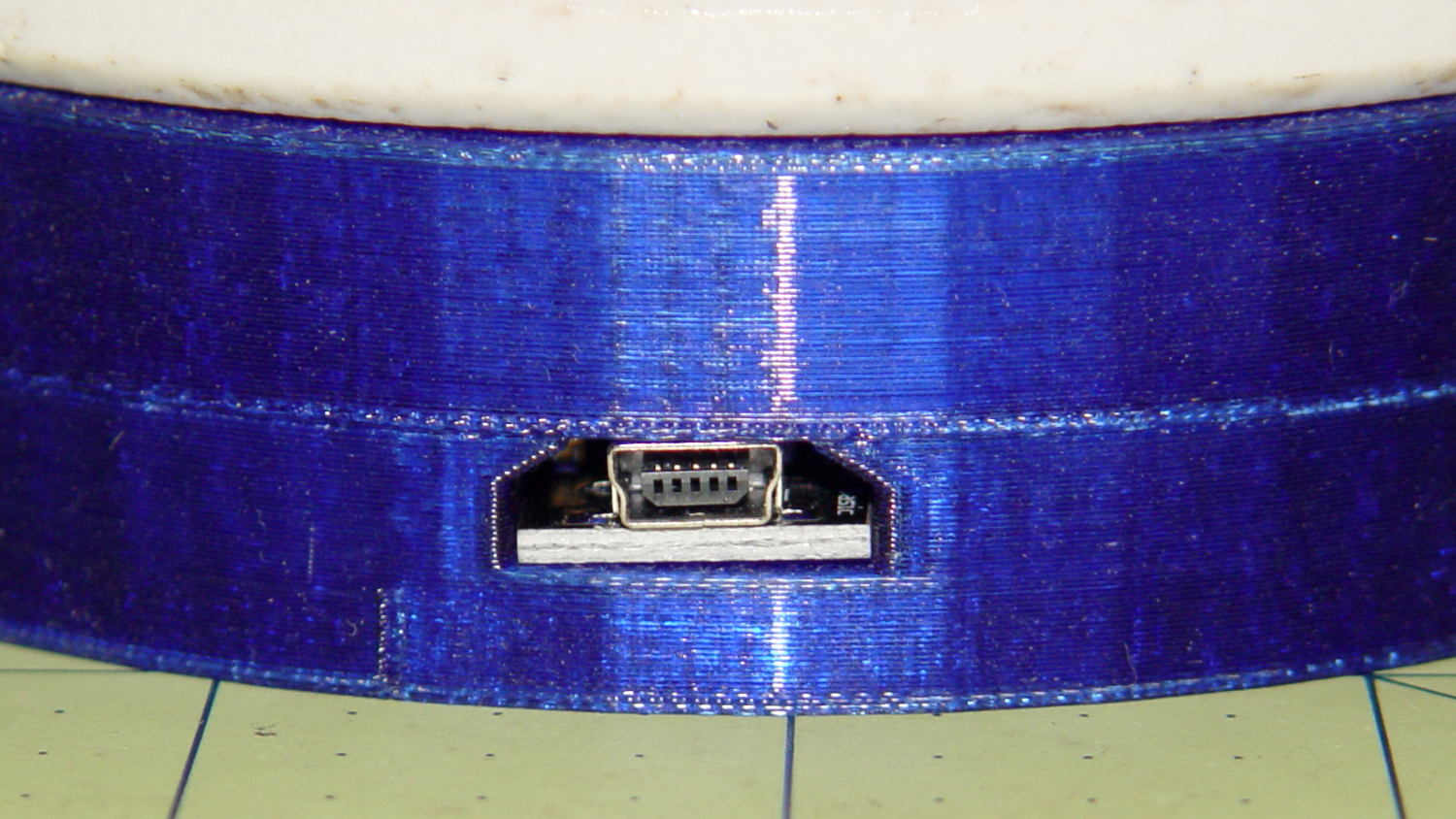
There’s an ugly story behind the horizontal line just above the USB adapter that I’ll explain in a bit.
The adapter hole begins 1.2 mm above the interior floor to let the adapter sit on a strip of double-sticky foam tape. I removed the standard header socket and wired the adapter directly to the Arduino Pro Mini with 24 AWG U-wires:
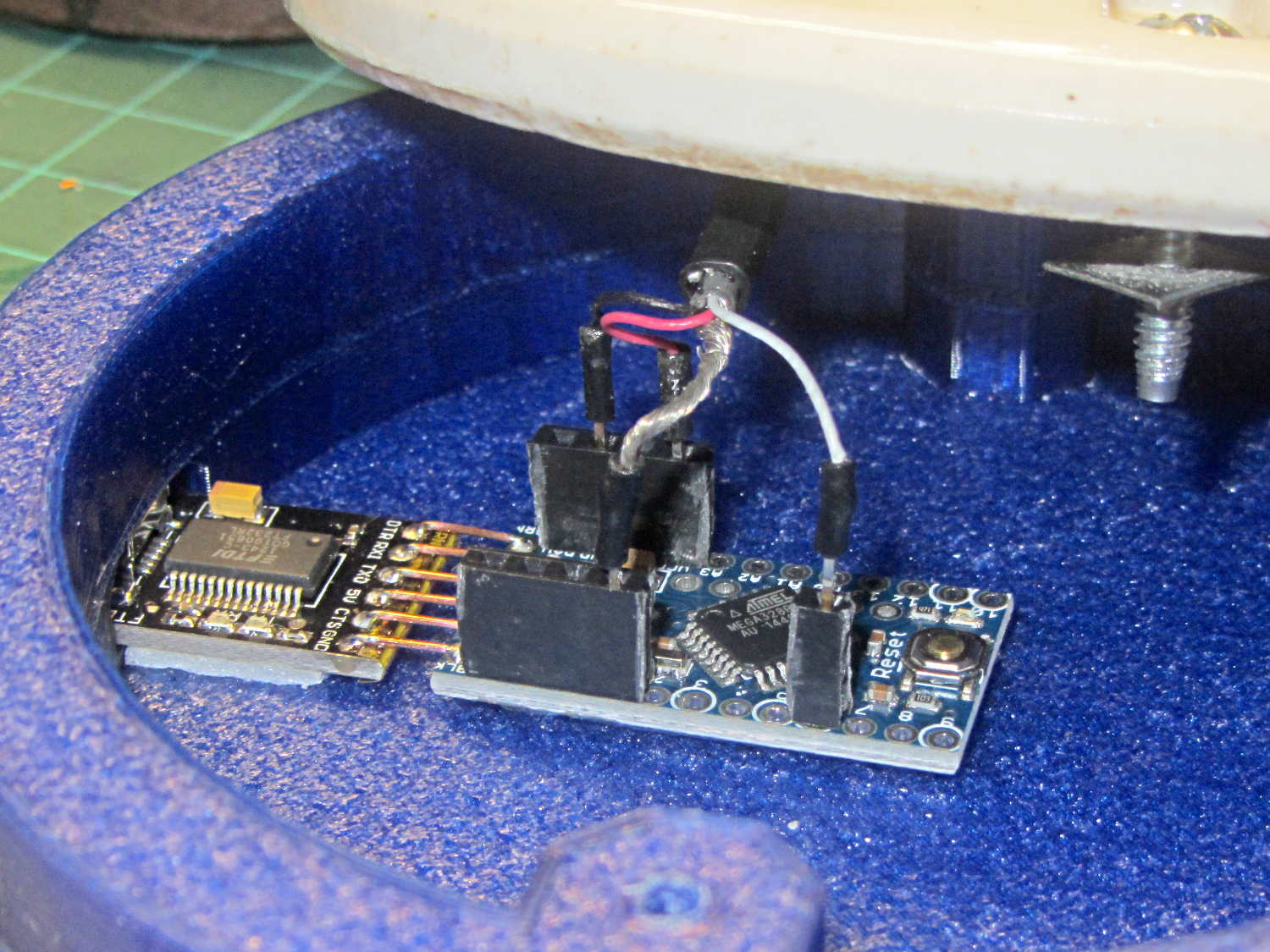
I didn’t want to use pin connectors on the lamp cable leads, but without those you (well, I) can’t take the base off without un-/re-soldering the wires in an awkward location; the fact that I hope to never take it apart is irrelevant. Next time, I’ll use a longer wire from the plate cap and better connectors, but this was a trial fit that became Good Enough for the purpose.
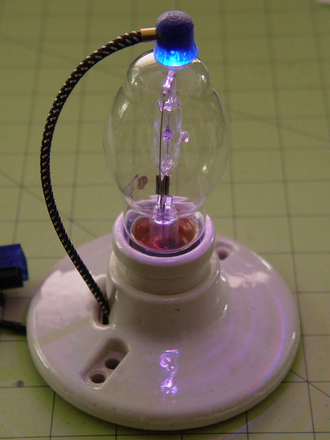
And then It Just Worked… although black, rather than cyan, plastic would look spiffier.
Bluish phases look icy cold:

Reddish phases look Just Right for a hot lamp:

A ring of white double sided foam tape now holds the plate cap in place; that should be black, too.
The OpenSCAD source code adds the base to the plate cap as a GitHub gist:
| // Vacuum Tube LED Lights | |
| // Ed Nisley KE4ZNU January 2016 | |
| Layout = "LampBase"; // Show Build Cap LampBase USBPort | |
| Section = true; // cross-section the object | |
| //- Extrusion parameters must match reality! | |
| ThreadThick = 0.25; | |
| ThreadWidth = 0.40; | |
| HoleWindage = 0.2; | |
| Protrusion = 0.1; // make holes end cleanly | |
| inch = 25.4; | |
| function IntegerMultiple(Size,Unit) = Unit * ceil(Size / Unit); | |
| ID = 0; | |
| OD = 1; | |
| LENGTH = 2; | |
| Pixel = [7.0,10.0,3.0]; // ID = contact patch, OD = PCB dia, LENGTH = overall thickness | |
| //———————- | |
| // Useful routines | |
| module PolyCyl(Dia,Height,ForceSides=0) { // based on nophead's polyholes | |
| Sides = (ForceSides != 0) ? ForceSides : (ceil(Dia) + 2); | |
| FixDia = Dia / cos(180/Sides); | |
| cylinder(r=(FixDia + HoleWindage)/2, | |
| h=Height, | |
| $fn=Sides); | |
| } | |
| //———————- | |
| // Tube cap | |
| CapTube = [4.0,3/16 * inch,10.0]; // brass tube for flying lead to cap LED | |
| CapSize = [Pixel[ID],(Pixel[OD] + 3.0),(CapTube[OD] + 2*Pixel[LENGTH])]; | |
| CapSides = 6*4; | |
| module Cap() { | |
| difference() { | |
| union() { | |
| cylinder(d=CapSize[OD],h=(CapSize[LENGTH]),$fn=CapSides); // main cap body | |
| translate([0,0,CapSize[LENGTH]]) // rounded top | |
| scale([1.0,1.0,0.65]) | |
| sphere(d=CapSize[OD]/cos(180/CapSides),$fn=CapSides); // cos() fixes slight undersize vs cylinder | |
| cylinder(d1=(CapSize[OD] + 2*3*ThreadWidth),d2=CapSize[OD],h=1.5*Pixel[LENGTH],$fn=CapSides); // skirt | |
| } | |
| translate([0,0,-Protrusion]) // bore for wiring to LED | |
| PolyCyl(CapSize[ID],(CapSize[LENGTH] + 3*ThreadThick + Protrusion),CapSides); | |
| translate([0,0,-Protrusion]) // PCB recess with clearance for tube dome | |
| PolyCyl(Pixel[OD],(1.5*Pixel[LENGTH] + Protrusion),CapSides); | |
| translate([0,0,(1.5*Pixel[LENGTH] – Protrusion)]) // small step + cone to retain PCB | |
| cylinder(d1=(Pixel[OD]/cos(180/CapSides)),d2=Pixel[ID],h=(Pixel[LENGTH] + Protrusion),$fn=CapSides); | |
| translate([0,0,(CapSize[LENGTH] – CapTube[OD]/(2*cos(180/8)))]) // hole for brass tube holding wire loom | |
| rotate([90,0,0]) rotate(180/8) | |
| PolyCyl(CapTube[OD],CapSize[OD],8); | |
| } | |
| } | |
| //———————- | |
| // Aperture for USB-to-serial adapter snout | |
| // These are all magic numbers, of course | |
| module USBPort() { | |
| translate([0,28.0]) | |
| rotate([90,0,0]) | |
| linear_extrude(height=28.0) | |
| polygon(points=[ | |
| [0,0], | |
| [8.0,0], | |
| [8.0,4.0], | |
| // [4.0,4.0], | |
| [4.0,6.5], | |
| [-4.0,6.5], | |
| // [-4.0,4.0], | |
| [-8.0,4.0], | |
| [-8.0,0], | |
| ]); | |
| } | |
| //———————- | |
| // Box for Leviton ceramic lamp base | |
| module LampBase() { | |
| Bottom = 5.0; | |
| Base = [3.75*inch,4.5*inch,25.0 + Bottom]; | |
| Sides = 12*4; | |
| Stud = [0.107 * inch,15.0,Base[LENGTH]]; // 6-32 mounting screws, OD = ceramic boss size | |
| StudOC = 3.5 * inch; | |
| union() { | |
| difference() { | |
| rotate(180/Sides) | |
| cylinder(d=Base[OD],h=Base[LENGTH],$fn=Sides); | |
| rotate(180/Sides) | |
| translate([0,0,Bottom]) | |
| cylinder(d=Base[ID],h=Base[LENGTH],$fn=Sides); | |
| translate([0,-Base[OD]/2,Bottom + 1.2]) // mount on double-sided foam tape | |
| rotate(0) | |
| USBPort(); | |
| } | |
| for (i = [-1,1]) | |
| translate([i*StudOC/2,0,0]) | |
| rotate(180/8) | |
| difference() { | |
| cylinder(d=Stud[OD],h=Stud[LENGTH],$fn=8); | |
| translate([0,0,Bottom]) | |
| PolyCyl(Stud[ID],(Stud[LENGTH] – (Bottom – Protrusion)),6); | |
| } | |
| } | |
| } | |
| //———————- | |
| // Build it | |
| if (Layout == "Cap") { | |
| if (Section) | |
| difference() { | |
| Cap(); | |
| translate([-CapSize[OD],0,CapSize[LENGTH]]) | |
| cube([2*CapSize[OD],2*CapSize[OD],3*CapSize[LENGTH]],center=true); | |
| } | |
| else | |
| Cap(); | |
| } | |
| if (Layout == "LampBase") | |
| LampBase(); | |
| if (Layout == "USBPort") | |
| USBPort(); | |
| if (Layout == "Build") { | |
| Cap(); | |
| Spigot(); | |
| } |

Comments
2 responses to “Vacuum Tube LEDs: Halogen Lamp Base”
Is that double sticky foam tape strong enough for mini USB mating/demating? I just had a micro USB connector pop off a board from the force.
I picked up several sticks of those Samtron style female headers from a surplus outfit some time back and became quite fond of them for exactly the sort of use you’re putting them to here. Alas, the surplus supply has run out, and they’re annoyingly expensive as new parts.
The USB board has enough footprint that the bond should last until the tape rots out.
The Mini-B connector shell has four good-size pads soldered to the board, but I’ll agree it’s not intended to anchor a long cable into an immovable object. Most likely, turning this into a “real product” will require epoxy embedding or a rugged coaxial power jack that doesn’t support programming.
Trouble is, these days you can’t get dirt-cheap wall warts with coaxial plugs…