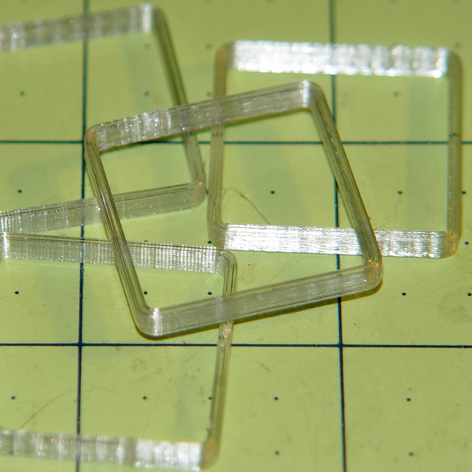
The Smell of Molten Projects in the Morning

Ed Nisley's Blog: Shop notes, electronics, firmware, machinery, 3D printing, laser cuttery, and curiosities. Contents: 100% human thinking, 0% AI slop.

Category: Machine Shop

Mechanical widgetry

  • Vacuum Tube LEDs: First Light!

    A test lashup to see how it all works, with an ersatz plate cap atop the IBM 21HB5A Beam Power tube on the far right end:

    Vacuum Tube LEDs - test lashup
    Vacuum Tube LEDs – test lashup

    Those sockets must mount in a chassis, not flop around loose on the cable.

    I hacked the code out of the Hard Drive Platter Mood Light; there’s a lot to not like about what’s left and I must rethink the overall structure. The colors now run an order of magnitude faster than the Platter Mood Light, with a 90° phase angle between successive Neopixels.

    The mica spacers in the 12AT7 Dual Triode tube (second in the sequence, Noval socket) look cool & crystalline:

    Vacuum Tube LEDs - Noval tube - blue phase
    Vacuum Tube LEDs – Noval tube – blue phase

    When the red phase comes around, it becomes a firebottle:

    Vacuum Tube LEDs - Noval tube - red phase
    Vacuum Tube LEDs – Noval tube – red phase

    With a touch of fire in its hole, the IBM 21HB5A Beam Power tube looks just flat-out gorgeous, despite that translucent blue plate cap:

    Vacuum Tube LEDs - IBM 21HB5A Beam Power Tube - violet amber phase
    Vacuum Tube LEDs – IBM 21HB5A Beam Power Tube – violet amber phase

    Cool green works pretty well:

    Vacuum Tube LEDs - IBM 21HB5A Beam Power Tube - green violet phase
    Vacuum Tube LEDs – IBM 21HB5A Beam Power Tube – green violet phase

    If you wait long enough, it’ll probably turn True IBM Blue.

    This worked out even better than I expected!

    The Arduino source code as a GitHub gist:

    // Neopixel lighting for multiple vacuum tubes
    // Ed Nisley – KE4ANU – January 2015
    #include <Adafruit_NeoPixel.h>
    //———-
    // Pin assignments
    const byte PIN_NEO = A3; // DO – data out to first Neopixel
    const byte PIN_HEARTBEAT = 13; // DO – Arduino LED
    //———-
    // Constants
    #define UPDATEINTERVAL 25ul
    const unsigned long UpdateMS = UPDATEINTERVAL – 1ul; // update LEDs only this many ms apart minus loop() overhead
    // number of steps per cycle, before applying prime factors
    #define RESOLUTION 100
    // phase difference between tubes for slowest color
    #define BASEPHASE (PI/4.0)
    // number of LED strips around each tube
    #define LEDSTRIPCOUNT 1
    // number of LEDs per strip
    #define LEDSTRINGCOUNT 5
    // want to randomize the startup a little?
    #define RANDOMIZE true
    //———-
    // Globals
    // instantiate the Neopixel buffer array
    Adafruit_NeoPixel strip = Adafruit_NeoPixel(LEDSTRIPCOUNT * LEDSTRINGCOUNT, PIN_NEO, NEO_GRB + NEO_KHZ800);
    uint32_t FullWhite = strip.Color(255,255,255);
    uint32_t FullOff = strip.Color(0,0,0);
    struct pixcolor_t {
    byte Prime;
    unsigned int NumSteps;
    unsigned int Step;
    float StepSize;
    float TubePhase;
    byte MaxPWM;
    };
    // colors in each LED
    enum pixcolors {RED, GREEN, BLUE, PIXELSIZE};
    struct pixcolor_t Pixels[PIXELSIZE]; // all the data for each pixel color intensity
    byte Map[LEDSTRINGCOUNT][LEDSTRIPCOUNT] = {{0},{1},{2},{3},{4}}; // pixel IDs around each tube, bottom to top.
    unsigned long MillisNow;
    unsigned long MillisThen;
    //– Figure PWM based on current state
    byte StepColor(byte Color, float Phi) {
    byte Value;
    Value = (Pixels[Color].MaxPWM / 2.0) * (1.0 + sin(Pixels[Color].Step * Pixels[Color].StepSize + Phi));
    // Value = (Value) ? Value : Pixels[Color].MaxPWM; // flash at dimmest points
    // printf("C: %d Phi: %d Value: %d\r\n",Color,(int)(Phi*180.0/PI),Value);
    return Value;
    }
    //– Helper routine for printf()
    int s_putc(char c, FILE *t) {
    Serial.write(c);
    }
    //——————
    // Set the mood
    void setup() {
    pinMode(PIN_HEARTBEAT,OUTPUT);
    digitalWrite(PIN_HEARTBEAT,LOW); // show we arrived
    Serial.begin(57600);
    fdevopen(&s_putc,0); // set up serial output for printf()
    printf("Multiple Vacuum Tube Mood Light with Neopixels\r\nEd Nisley – KE4ZNU – January 2016\r\n");
    /// set up Neopixels
    strip.begin();
    strip.show();
    // lamp test: run a brilliant white dot along the length of the strip
    printf("Lamp test: walking white\r\n");
    strip.setPixelColor(0,FullWhite);
    strip.show();
    delay(500);
    for (int i=1; i<strip.numPixels(); i++) {
    digitalWrite(PIN_HEARTBEAT,HIGH);
    strip.setPixelColor(i-1,FullOff);
    strip.setPixelColor(i,FullWhite);
    strip.show();
    digitalWrite(PIN_HEARTBEAT,LOW);
    delay(500);
    }
    strip.setPixelColor(strip.numPixels() – 1,FullOff);
    strip.show();
    delay(500);
    // fill the layers
    printf(" … fill using Map array\r\n");
    for (int i=0; i < LEDSTRINGCOUNT; i++) { // for each layer
    digitalWrite(PIN_HEARTBEAT,HIGH);
    for (int j=0; j < LEDSTRIPCOUNT; j++) { // spread color around the layer
    strip.setPixelColor(Map[i][j],FullWhite);
    strip.show();
    delay(250);
    }
    digitalWrite(PIN_HEARTBEAT,LOW);
    }
    // clear to black
    printf(" … clear\r\n");
    for (int i=0; i < LEDSTRINGCOUNT; i++) { // for each layer
    digitalWrite(PIN_HEARTBEAT,HIGH);
    for (int j=0; j < LEDSTRIPCOUNT; j++) { // spread color around the layer
    strip.setPixelColor(Map[i][j],FullOff);
    strip.show();
    delay(250);
    }
    digitalWrite(PIN_HEARTBEAT,LOW);
    }
    delay(1000);
    // set up the color generators
    MillisNow = MillisThen = millis();
    if (RANDOMIZE)
    randomSeed(MillisNow + analogRead(7));
    else
    printf("Start not randomized\r\n");
    printf("First random number: %ld\r\n",random(10));
    Pixels[RED].Prime = 7;
    Pixels[GREEN].Prime = 5;
    Pixels[BLUE].Prime = 3;
    printf("Primes: (%d,%d,%d)\r\n",Pixels[RED].Prime,Pixels[GREEN].Prime,Pixels[BLUE].Prime);
    unsigned int TubeSteps = (unsigned int) ((BASEPHASE / TWO_PI) *
    RESOLUTION * (unsigned int) max(max(Pixels[RED].Prime,Pixels[GREEN].Prime),Pixels[BLUE].Prime));
    printf("Tube phase offset: %d deg = %d steps\r\n",(int)(BASEPHASE*(360.0/TWO_PI)),TubeSteps);
    Pixels[RED].MaxPWM = 255;
    Pixels[GREEN].MaxPWM = 128;
    Pixels[BLUE].MaxPWM = 255;
    for (byte c=0; c < PIXELSIZE; c++) {
    Pixels[c].NumSteps = RESOLUTION * (unsigned int) Pixels[c].Prime;
    Pixels[c].Step = (RANDOMIZE) ? random(Pixels[c].NumSteps) : (3*Pixels[c].NumSteps)/4;
    Pixels[c].StepSize = TWO_PI / Pixels[c].NumSteps; // in radians per step
    Pixels[c].TubePhase = TubeSteps * Pixels[c].StepSize; // radians per tube
    printf("c: %d Steps: %d Init: %d",c,Pixels[c].NumSteps,Pixels[c].Step);
    printf(" PWM: %d Phi %d deg\r\n",Pixels[c].MaxPWM,(int)(Pixels[c].TubePhase*(360.0/TWO_PI)));
    }
    }
    //——————
    // Run the mood
    void loop() {
    MillisNow = millis();
    if ((MillisNow – MillisThen) > UpdateMS) {
    digitalWrite(PIN_HEARTBEAT,HIGH);
    for (byte c=0; c < PIXELSIZE; c++) { // step to next increment in each color
    if (++Pixels[c].Step >= Pixels[c].NumSteps) {
    Pixels[c].Step = 0;
    printf("Cycle %d steps %d at %8ld delta %ld ms\r\n",c,Pixels[c].NumSteps,MillisNow,(MillisNow – MillisThen));
    }
    }
    for (int i=0; i < LEDSTRINGCOUNT; i++) { // for each layer
    byte Value[PIXELSIZE];
    for (byte c=0; c < PIXELSIZE; c++) { // … for each color
    Value[c] = StepColor(c,-i*Pixels[c].TubePhase); // figure new PWM value
    // Value[c] = (c == RED && Value[c] == 0) ? Pixels[c].MaxPWM : Value[c]; // flash highlight for tracking
    }
    uint32_t UniColor = strip.Color(Value[RED],Value[GREEN],Value[BLUE]);
    if (false && (i == 0))
    printf("L: %d C: %08lx\r\n",i,UniColor);
    for (int j=0; j < LEDSTRIPCOUNT; j++) { // fill layer with color
    strip.setPixelColor(Map[i][j],UniColor);
    }
    }
    strip.show();
    MillisThen = MillisNow;
    digitalWrite(PIN_HEARTBEAT,LOW);
    }
    }
    view raw MultiTube.ino hosted with ❤ by GitHub
  • Vacuum Tube LEDs: Ersatz Tube Sockets

    Even vacuum tubes destined to be decorations need sockets:

    Vacuum Tube Bases - solid models
    Vacuum Tube Bases – solid models

    They’re entirely plastic, of course, but they match the dimensions of “real” tube sockets pretty closely. The bosses around the pins have hard-inch dimensions, so you (well, I) can unleash Genuine Greenlee Radio Chassis Punches on sheet metal.

    All the key dimensions come from a table, so you can build whatever sockets you need. These four seem to cover the most common relics of the Hollow State Empire:

    T_NAME = 0;                                             // common name
    T_NUMPINS = 1;                                          // total, with no allowance for keying
    T_PINBCD = 2;                                           // tube pin circle diameter
    T_PINOD = 3;                                            //  ... diameter
    T_PINLEN = 4;                                           //  ... length (overestimate)
    T_HOLEOD = 5;                                           // nominal panel hole from various sources
    T_PUNCHOD = 6;                                          // panel hole optimized for inch-size Greenlee punches
    T_TUBEOD = 7;                                           // envelope or base diameter
    T_PIPEOD = 8;                                           // light pipe from LED to tube base
    T_SCREWOC = 9;                                          // mounting screw holes
    
    //    Name      pins     BCD   dia  length   hole            punch       env  pipe screw
    TubeData = [
        ["Mini7",     8,    9.53, 1.016,   7.0,  16.0,        11/16 * inch,  18.0,  5.0, 22.5],
        ["Octal",     8,   17.45, 2.36,   10.0,  36.2,    (8 + 1)/8 * inch,  32.0, 11.5, 39.0],
        ["Noval",    10,   11.89, 1.1016,  7.0,  22.0,          7/8 * inch,  21.0,  5.0, 28.0],
        ["Duodecar", 13,   19.10, 1.05,    9.0,  32.0,         1.25 * inch,  38.0, 12.5, 39.0],
    ];
    

    Given that the tubes lack electrical connections, I omitted the base keying: plug them in for best visual effect.

    The hole through the middle passes light from a knockoff Neopixel on a 10 mm OD PCB:

    Vacuum Tube LEDs - Octal base - top
    Vacuum Tube LEDs – Octal base – top

    Seen from the bottom, each base traps a pair of 6-32 nuts for chassis mounting and has a Neopixel press-fit in the middle:

    Vacuum Tube LEDs - Duodecar base - bottom
    Vacuum Tube LEDs – Duodecar base – bottom

    Those recesses require support structures:

    Vacuum Tube Bases - solid models - support
    Vacuum Tube Bases – solid models – support

    The Miniature 7-pin socket has the least space for the 10 mm OD Neopixel PCB and shows the thin layer between the bottom of the pin holes and the top of the openings.

    Vacuum Tube Base - Mini7 - solid model section
    Vacuum Tube Base – Mini7 – solid model section

    You see half of the eight holes in the “7 pin” socket, because it has the eighth hole where a standard socket has a gap between pins 1 and 7.

    Somewhat to my surprise, punching the support spiders out with a 6-32 stud (grabbed in the drill press) worked perfectly:

    Vacuum Tube Base - nut trap overhang - detail
    Vacuum Tube Base – nut trap overhang – detail

    They look like I intended to build tiny decorations:

    Vacuum Tube Base - support structure - detail
    Vacuum Tube Base – support structure – detail

    The cookies held on tenuously, then released with a loud bang! as I gradually increased the pressure. A PETG support structure in a blind recess wouldn’t pop out nearly so well.

    The OpenSCAD source code as a GitHub gist:

    // Vacuum Tube LED Lights
    // Ed Nisley KE4ZNU January 2016
    Layout = "Sockets"; // Cap LampBase USBPort Socket(s)
    Section = true; // cross-section the object
    Support = true;
    //- Extrusion parameters must match reality!
    ThreadThick = 0.25;
    ThreadWidth = 0.40;
    HoleWindage = 0.2;
    Protrusion = 0.1; // make holes end cleanly
    inch = 25.4;
    function IntegerMultiple(Size,Unit) = Unit * ceil(Size / Unit);
    //———————-
    // Dimensions
    // https://en.wikipedia.org/wiki/Tube_socket#Summary_of_Base_Details
    T_NAME = 0; // common name
    T_NUMPINS = 1; // total, with no allowance for keying
    T_PINBCD = 2; // tube pin circle diameter
    T_PINOD = 3; // … diameter
    T_PINLEN = 4; // … length (overestimate)
    T_HOLEOD = 5; // nominal panel hole from various sources
    T_PUNCHOD = 6; // panel hole optimized for inch-size Greenlee punches
    T_TUBEOD = 7; // envelope or base diameter
    T_PIPEOD = 8; // light pipe from LED to tube base
    T_SCREWOC = 9; // mounting screw holes
    // Name pins BCD dia length hole punch env pipe screw
    TubeData = [
    ["Mini7", 8, 9.53, 1.016, 7.0, 16.0, 11/16 * inch, 18.0, 5.0, 22.5],
    ["Octal", 8, 17.45, 2.36, 10.0, 36.2, (8 + 1)/8 * inch, 32.0, 11.5, 39.0],
    ["Noval", 10, 11.89, 1.1016, 7.0, 22.0, 7/8 * inch, 21.0, 5.0, 28.0],
    ["Duodecar", 13, 19.10, 1.05, 9.0, 32.0, 1.25 * inch, 38.0, 12.5, 39.0],
    ];
    ID = 0;
    OD = 1;
    LENGTH = 2;
    Pixel = [7.0,10.0,3.0]; // ID = contact patch, OD = PCB dia, LENGTH = overall thickness
    Nut = [3.5,8.0,3.0]; // socket mounting nut recess
    BaseShim = 2*ThreadThick; // between pin holes and pixel top
    SocketFlange = 2.0; // rim around socket below punchout
    PanelThick = 2.0; // socket extension through punchout
    //———————-
    // Useful routines
    module PolyCyl(Dia,Height,ForceSides=0) { // based on nophead's polyholes
    Sides = (ForceSides != 0) ? ForceSides : (ceil(Dia) + 2);
    FixDia = Dia / cos(180/Sides);
    cylinder(r=(FixDia + HoleWindage)/2,h=Height,$fn=Sides);
    }
    //———————-
    // Tube cap
    CapTube = [4.0,3/16 * inch,10.0]; // brass tube for flying lead to cap LED
    CapSize = [Pixel[ID],(Pixel[OD] + 3.0),(CapTube[OD] + 2*Pixel[LENGTH])];
    CapSides = 6*4;
    module Cap() {
    difference() {
    union() {
    cylinder(d=CapSize[OD],h=(CapSize[LENGTH]),$fn=CapSides); // main cap body
    translate([0,0,CapSize[LENGTH]]) // rounded top
    scale([1.0,1.0,0.65])
    sphere(d=CapSize[OD]/cos(180/CapSides),$fn=CapSides); // cos() fixes slight undersize vs cylinder
    cylinder(d1=(CapSize[OD] + 2*3*ThreadWidth),d2=CapSize[OD],h=1.5*Pixel[LENGTH],$fn=CapSides); // skirt
    }
    translate([0,0,-Protrusion]) // bore for wiring to LED
    PolyCyl(CapSize[ID],(CapSize[LENGTH] + 3*ThreadThick + Protrusion),CapSides);
    translate([0,0,-Protrusion]) // PCB recess with clearance for tube dome
    PolyCyl(Pixel[OD],(1.5*Pixel[LENGTH] + Protrusion),CapSides);
    translate([0,0,(1.5*Pixel[LENGTH] – Protrusion)]) // small step + cone to retain PCB
    cylinder(d1=(Pixel[OD]/cos(180/CapSides)),d2=Pixel[ID],h=(Pixel[LENGTH] + Protrusion),$fn=CapSides);
    translate([0,0,(CapSize[LENGTH] – CapTube[OD]/(2*cos(180/8)))]) // hole for brass tube holding wire loom
    rotate([90,0,0]) rotate(180/8)
    PolyCyl(CapTube[OD],CapSize[OD],8);
    }
    }
    //———————-
    // Aperture for USB-to-serial adapter snout
    // These are all magic numbers, of course
    module USBPort() {
    translate([0,28.0])
    rotate([90,0,0])
    linear_extrude(height=28.0)
    polygon(points=[
    [0,0],
    [8.0,0],
    [8.0,4.0],
    // [4.0,4.0],
    [4.0,6.5],
    [-4.0,6.5],
    // [-4.0,4.0],
    [-8.0,4.0],
    [-8.0,0],
    ]);
    }
    //———————-
    // Box for Leviton ceramic lamp base
    module LampBase() {
    Bottom = 3.0;
    Base = [4.0*inch,4.5*inch,20.0 + Bottom];
    Sides = 12*4;
    Retainer = [3.5,11.0,1.0]; // flat fiber washer holding lamp base screws in place
    StudSides = 8;
    StudOC = 3.5 * inch;
    Stud = [0.107 * inch, // 6-32 mounting screws
    min(15.0,1.5*(Base[ID] – StudOC)/cos(180/StudSides)), // OD = big enough to merge with walls
    (Base[LENGTH] – Retainer[LENGTH])]; // leave room for retainer
    union() {
    difference() {
    rotate(180/Sides)
    cylinder(d=Base[OD],h=Base[LENGTH],$fn=Sides);
    rotate(180/Sides)
    translate([0,0,Bottom])
    cylinder(d=Base[ID],h=Base[LENGTH],$fn=Sides);
    translate([0,-Base[OD]/2,Bottom + 1.2]) // mount on double-sided foam tape
    rotate(0)
    USBPort();
    }
    for (i = [-1,1])
    translate([i*StudOC/2,0,0])
    rotate(180/StudSides)
    difference() {
    # cylinder(d=Stud[OD],h=Stud[LENGTH],$fn=StudSides);
    translate([0,0,Bottom])
    PolyCyl(Stud[ID],(Stud[LENGTH] – (Bottom – Protrusion)),6);
    }
    }
    }
    //———————-
    // Tube Socket
    module Socket(Name = "Mini7") {
    NumSides = 6*4;
    Tube = search([Name],TubeData,1,0)[0];
    echo(str("Building ",TubeData[Tube][0]," socket"));
    echo(str(" Punch: ",TubeData[ID][T_PUNCHOD]," mm = ",TubeData[ID][T_PUNCHOD]/inch," inch"));
    echo(str(" Screws: ",TubeData[ID][T_SCREWOC]," mm =",TubeData[ID][T_SCREWOC]/inch," inch OC"));
    OAH = Pixel[LENGTH] + BaseShim + TubeData[Tube][T_PINLEN];
    BaseHeight = OAH – PanelThick;
    difference() {
    union() {
    linear_extrude(height=BaseHeight)
    hull() {
    circle(d=(TubeData[Tube][T_PUNCHOD] + 2*SocketFlange),$fn=NumSides);
    for (i=[-1,1])
    translate([i*TubeData[Tube][T_SCREWOC]/2,0])
    circle(d=2*Nut[OD],$fn=NumSides);
    }
    cylinder(d=TubeData[Tube][T_PUNCHOD],h=OAH,$fn=NumSides);
    }
    for (i=[0:(TubeData[Tube][T_NUMPINS] – 1)]) // tube pins
    rotate(i*360/TubeData[Tube][T_NUMPINS])
    translate([TubeData[Tube][T_PINBCD]/2,0,(OAH – TubeData[Tube][T_PINLEN])])
    rotate(180/4)
    PolyCyl(TubeData[Tube][T_PINOD],(TubeData[Tube][T_PINLEN] + Protrusion),4);
    for (i=[-1,1]) // mounting screw holes & nut traps
    translate([i*TubeData[Tube][T_SCREWOC]/2,0,-Protrusion]) {
    PolyCyl(Nut[OD],(Nut[LENGTH] + Protrusion),6);
    PolyCyl(Nut[ID],(OAH + 2*Protrusion),6);
    }
    translate([0,0,-Protrusion]) { // LED recess
    PolyCyl(Pixel[OD],(Pixel[LENGTH] + Protrusion),8);
    }
    translate([0,0,(Pixel[LENGTH] – Protrusion)]) { // light pipe
    rotate(180/TubeData[Tube][T_NUMPINS])
    PolyCyl(TubeData[Tube][T_PIPEOD],(OAH + 2*Protrusion),TubeData[Tube][T_NUMPINS]);
    }
    }
    // Totally ad-hoc support structures …
    if (Support) {
    color("Yellow") {
    for (i=[-1,1]) // nut traps
    translate([i*TubeData[Tube][T_SCREWOC]/2,0,(Nut[LENGTH] – ThreadThick)/2])
    for (a=[0:5])
    rotate(a*30 + 15)
    cube([2*ThreadWidth,0.9*Nut[OD],(Nut[LENGTH] – ThreadThick)],center=true);
    if (Pixel[OD] > TubeData[Tube][T_PIPEOD]) // support pipe only if needed
    translate([0,0,(Pixel[LENGTH] – ThreadThick)/2])
    for (a=[0:7])
    rotate(a*22.5)
    cube([2*ThreadWidth,0.9*Pixel[OD],(Pixel[LENGTH] – ThreadThick)],center=true);
    }
    }
    }
    //———————-
    // Build it
    if (Layout == "Cap") {
    if (Section)
    difference() {
    Cap();
    translate([-CapSize[OD],0,CapSize[LENGTH]])
    cube([2*CapSize[OD],2*CapSize[OD],3*CapSize[LENGTH]],center=true);
    }
    else
    Cap();
    }
    if (Layout == "LampBase")
    LampBase();
    if (Layout == "USBPort")
    USBPort();
    if (Layout == "Socket")
    if (Section) {
    difference() {
    Socket();
    translate([-100/2,0,-Protrusion])
    cube([100,50,50],center=false);
    }
    }
    else
    Socket();
    if (Layout == "Sockets") {
    translate([0,50,0])
    Socket("Mini7");
    translate([0,20,0])
    Socket("Octal");
    translate([0,-15,0])
    Socket("Duodecar");
    translate([0,-50,0])
    Socket("Noval");
    }


  • Sears Sewing Table Hinge Covers

    The extension surfaces on the Sears sewing table in the Basement Sewing Room unfold from the top, leaving the hinges exposed:

    Sears Sewing Table - hinge
    Sears Sewing Table – hinge

    Alas, quilts snag on the squared-off ends of the hinges, a situation that is not to be tolerated…

    This protective cap isn’t as small as we’d like, but it must be that thick to cover the hinge, that long to cover the squared-off ends, and that wide for symmetry:

    Sears Sewing Table Hinge Cover - solid model
    Sears Sewing Table Hinge Cover – solid model

    Two neodymium magnets fit in the holes and secure the cover to the all-steel “bronzed” hinges:

    Sears Sewing Table - hinge covers
    Sears Sewing Table – hinge covers

    We’re not sure how well that will work in the long term, but early returns seem promising.

    It could be slightly narrower left-to-right and maybe fewer vertices should be oriented differently.

    The OpenSCAD source code as a GitHub gist:

    // Vacuum Tube LED Lights
    // Ed Nisley KE4ZNU January 2016
    //- Extrusion parameters must match reality!
    ThreadThick = 0.20;
    ThreadWidth = 0.40;
    HoleWindage = 0.2;
    Protrusion = 0.1; // make holes end cleanly
    inch = 25.4;
    function IntegerMultiple(Size,Unit) = Unit * ceil(Size / Unit);
    //———————-
    // Dimensions
    Hinge = [7.0,52.0,6.0];
    TopThick = 3*ThreadThick;
    PlateThick = Hinge[2] + TopThick;
    NumSides = 8*4;
    //———————-
    // Useful routines
    module PolyCyl(Dia,Height,ForceSides=0) { // based on nophead's polyholes
    Sides = (ForceSides != 0) ? ForceSides : (ceil(Dia) + 2);
    FixDia = Dia / cos(180/Sides);
    cylinder(r=(FixDia + HoleWindage)/2,h=Height,$fn=Sides);
    }
    //———————-
    // Build it
    difference() {
    hull()
    for (a=[0:7])
    rotate(a*360/8)
    translate([Hinge[1]/2,0,0])
    scale([1.5,1.5,1])
    sphere(r=PlateThick,$fn=NumSides);
    hull()
    for (k=[-1,1])
    translate([0,Hinge[1]/2,k*(Hinge[2] – Hinge[0]/2)])
    rotate([90,0,0]) rotate(180/8)
    PolyCyl(Hinge[0],Hinge[1],8);
    for (i=[-1,1])
    translate([i*Hinge[1]/2,0,-Protrusion])
    PolyCyl(4.8,2.5 + Protrusion,8);
    translate([0,0,-PlateThick])
    cube(2*[Hinge[1],Hinge[1],PlateThick],center=true);
    }
  • Hollow State Electronics: Desk Decorations

    I did a lightning talk / show-n-tell last Tuesday at the MHV LUG meeting and covered one end of a table with the Neopixel-lit bulbs & vacuum tubes & hard drive platters I’ve been playing with:

    MHVLUG – Hollow State Decorations – Lightning Talk

    Some of the posts won’t go live for a week, but here’s a peek into the future:

    Vacuum Tube LEDs - IBM 21HB5A Beam Power Tube - violet amber phase
    Vacuum Tube LEDs – IBM 21HB5A Beam Power Tube – violet amber phase

    Dang, that came out well…

  • Vacuum Tube LEDs: Halogen Lamp Success

    The Neopixel-illuminated halogen lamp looks much, much better than I expected:

    Vacuum Tube LEDs - halogen lamp - red phase
    Vacuum Tube LEDs – halogen lamp – red phase

    The ceramic ring screws down around the socket shell and pulls it up against the base; the threads have only as much precision as required to keep it from falling off. I may need to add a leveling shim just so I don’t have to explain why it’s always crooked.

  • Knurled Metric Inserts

    These seem like they ought to come in handy for fastening things to 3D printed objects:

    Kurled Inserts - M2 M3 M5
    Kurled Inserts – M2 M3 M5

    The assorted screws come from the Small Can o’ Small Screwlike Things, all harvested from various dead bits of consumer electronics:

    Kurled M3 Inserts
    Kurled M3 Inserts

    These would benefit from a heated staking tool that slides them into the hole parallel to the axis and flush with the surface. Such things are commercially available, of course, but for my simple needs something involving a cartridge heater, a wall wart, and a drill press may suffice.

    It would be better if the inserts had actual knurls, rather than splines. So it goes.

    For the record (thread x length x Knurl OD x Body OD):

    • M2 x 4 x 3.5 x 2.8
    • M2 x 6 x 3.5 x 2.7
    • M3 x 4 x 4.5 x 3.8
    • M3 x 8 x 5.0 x 3.9
    • M5 x 10 x 7.5 x 6.9

    The actual measurements seem to vary within ±0.02 of nominal and I doubt the manufacturing consistency justifies any assumption tighter than ±0.1 mm.

    The M3 inserts really do have two different ODs.

    The M5 insert was listed as “7 mm OD” and measures 7.5 mm, which suggests a typo in the description.

    The polygonal hole adjustment I use produces dead-on diameters for small vertical holes:

    HoleWindage = 0.2;
    
    module PolyCyl(Dia,Height,ForceSides=0) {	// based on nophead's polyholes
      Sides = (ForceSides != 0) ? ForceSides : (ceil(Dia) + 2);
      FixDia = Dia / cos(180/Sides);
      cylinder(d=(FixDia + HoleWindage),h=Height,$fn=Sides);
    }
    

    So an ordinary cylinder() with the nominal knurl OD or a PolyCyl() with the nominal body OD should suffice. Horizontal holes can probably use a plain old cylinder() with the nominal body OD, because they need reaming anyway.

    Perhaps a dab of epoxy would bond better with the plastic around a nominal-size hole than forcing the insert into an undersized hole or heat-bonding the insert. Some experimentation is in order.

    Ten bucks for the entire collection (five bags of 50 inserts each = 250 little brass doodads = 4¢ each), shipped free halfway around the planet, seemed reasonable, given that inch size knurled brass inserts run anywhere from 50¢ to upwards of $2 a pop and a Genuine Helicoil 4-40 insert sets you back just shy of a buck.

    An Amazon vendor offers 4-40 inserts for $0.24 each in single quantities, but with $9.25 shipping. [le sigh]

    Inch-size inserts with knurled rings intended for ultrasonic bonding seem to be 5¢ to 15¢ on eBay. I think the straight-side versions will work better than the tapered ones for heat or epoxy bonding.

    It knurls my knuckles that we here in the US haven’t gone solidly metric. Yes, I have a goodly assortment of metric hardware in addition to the harvested fasteners shown above, but it definitely wasn’t cheap & readily available.

  • Filament Drive Jam

    So, while printing the first pass of the halogen lamp base, this happened:

    Lamp Base - wrecked print
    Lamp Base – wrecked print

    The first layer went down fine, but the filament stopped feeding after laying down the small linear patch along the right side. The wrinkles come from me peeling it off the platform while it was still hot and flexy.

    Although feeding PETG at 75 mm/s for infill worked so far (I mean, sheesh, look at all the stuff I’ve made in the last year), this involved a fairly large expanse of filament and maybe, just maybe, the high flow rate cooled the nozzle enough to increase the extrusion pressure and eventually strip the filament.

    I shoved the filament hard enough to get it feeding again, bumped the extrusion temperature to 260 °C and started another print, whereupon things went swimmingly for the first 12.2 mm. Alas, the filament jammed again, just below the top of the hole for the USB adapter, where you see the odd line in the middle of the finished base:

    Lamp Base - USB port
    Lamp Base – USB port

    Because it’s now printing a relatively thin cylinder at relatively slow speeds (less infill per perimeter), the “feeding too fast” argument falls flat on its face: obviously, something else is wrong.

    Removing the fans showed a bit of plastic on the drive gear teeth, but nothing too terrible:

    M2 Filament Drive - jam front view
    M2 Filament Drive – jam front view

    The witness mark on the planetary gearbox output shaft still lines up with the mark on the gear, so the tiny grub screw hasn’t come loose. Note the slight misalignment between the bottom of the filament drive and the hot end inlet; I’ve already snipped the filament and done some retraction.

    A small struggle involving needle nose pliers dragged this classic gouged filament from the drive:

    Stripped PETG Filament
    Stripped PETG Filament

    This spool of PETG filament started out at 1.70 mm, but this section measures 1.80 mm. That’s at the high end of the ±0.05 mm tolerance around the nominal 1.75 mm, but, frankly, I don’t take the tolerance too seriously.

    Undamaged filament from the spool didn’t push smoothly through the drive, so I reamed out the entire path with a 2 mm drill (actually, a #46 drill = 2.05 mm). I don’t recall if I did that before mounting the drive, but even if I did, I’d expect some crud and distortion to accumulate after a while; it’s been running without much attention since last March.

    Reassembling the drive and feeding the filament to just above the hot end showed a slight misalignment:

    M2 Filament Dive - misaligned front view
    M2 Filament Dive – misaligned front view

    I cured that by loosening the screws and rotating the whole drive slightly clockwise:

    M2 Filament Dive - realigned front view
    M2 Filament Dive – realigned front view

    Viewed from the side, the drive positions the filament slightly too far to the rear:

    M2 Filament Dive - alignment side view
    M2 Filament Dive – alignment side view

    I didn’t (think to) check if the hole in the snout has become bellmouthed, but it wouldn’t take much. In any event, the filament fed into the hot end without incident, so maybe there’s enough slop to cover that misalignment. Maybe I should add a small shim behind the drive?

    With the filament drive working again, I had Slic3r chop the bottom off the solid model of the lamp base and create the G-Code for just the top section, which printed without any problem at all.

    I drilled eight holes in the bottom surface of the new ring, slobbered epoxy around the ring and tucked it into the holes, used a pair of brass rods to align the two parts, and clamped them together while the epoxy cured:

    Lamp Base - clamping
    Lamp Base – clamping

    I should be using black PETG anyway, so we’ll call this one a prototype and move on.

    So that’s where the line came from…