Ed Nisley's Blog: Shop notes, electronics, firmware, machinery, 3D printing, laser cuttery, and curiosities. Contents: 100% human thinking, 0% AI slop.
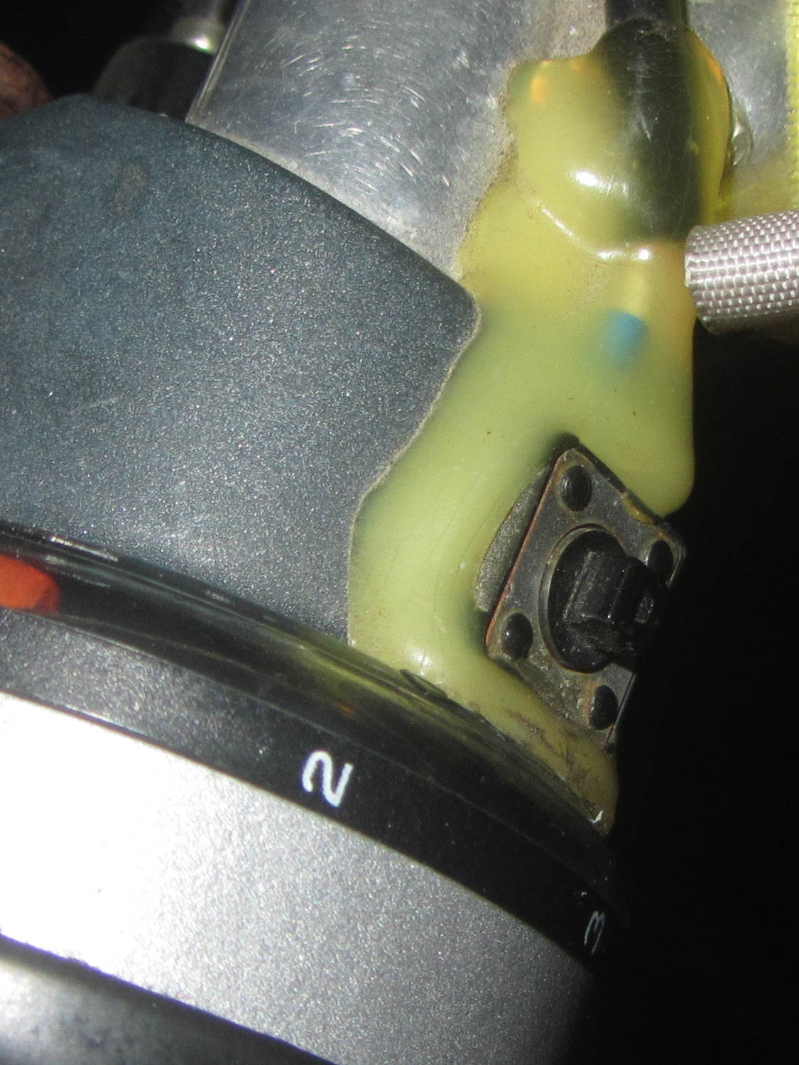
Long ago, Mary picked out a PTT switch with a raised, square post that provided a distinct shape and positive tactile feedback:
PTT Button – bare post
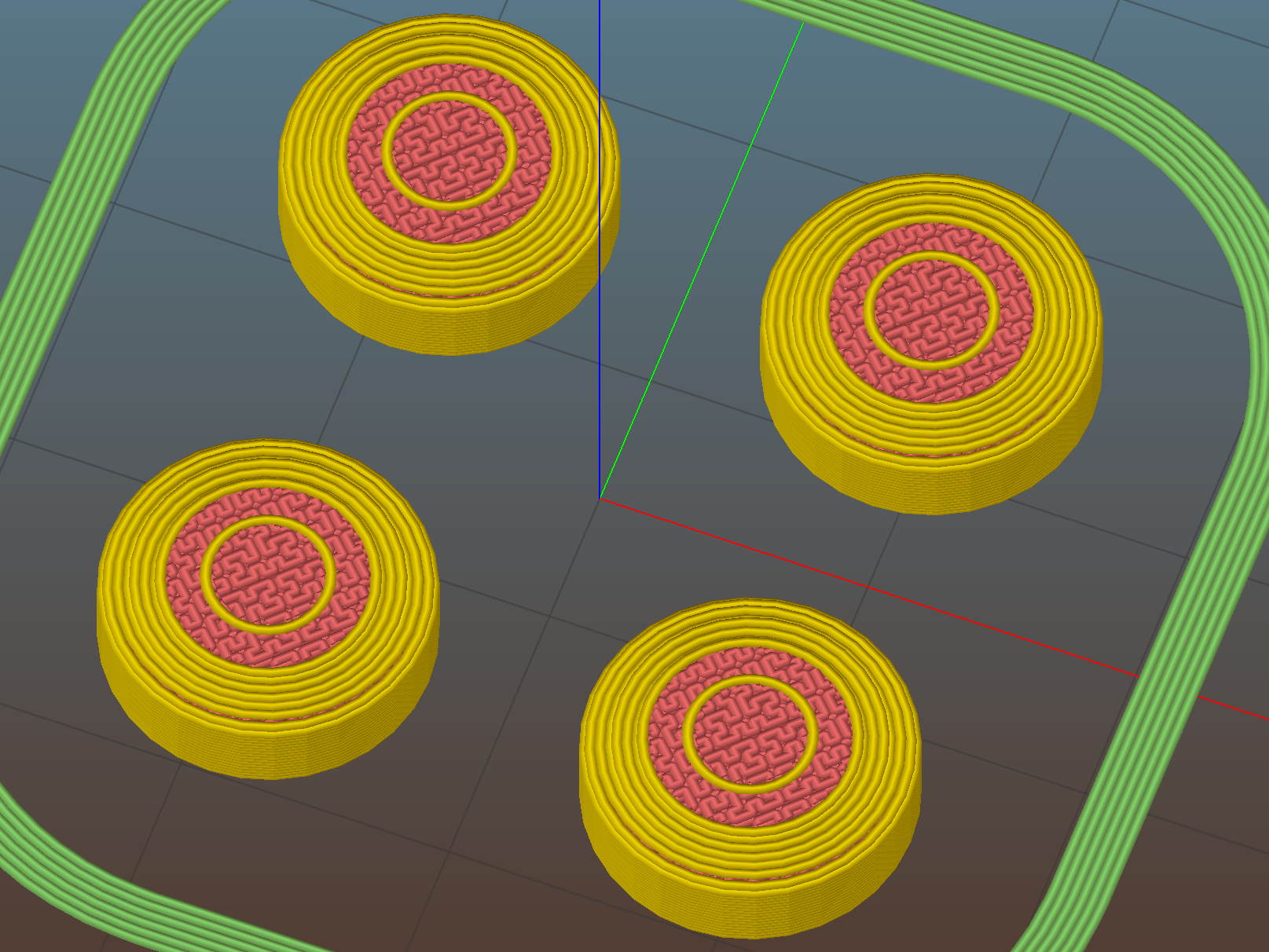
Time passes, she dinged her thumb in the garden, and asked for a more rounded button. I have some switches with rounded caps, but replacing the existing switch looked a lot like work, sooooo:
PTT Button Cap – Slic3r preview
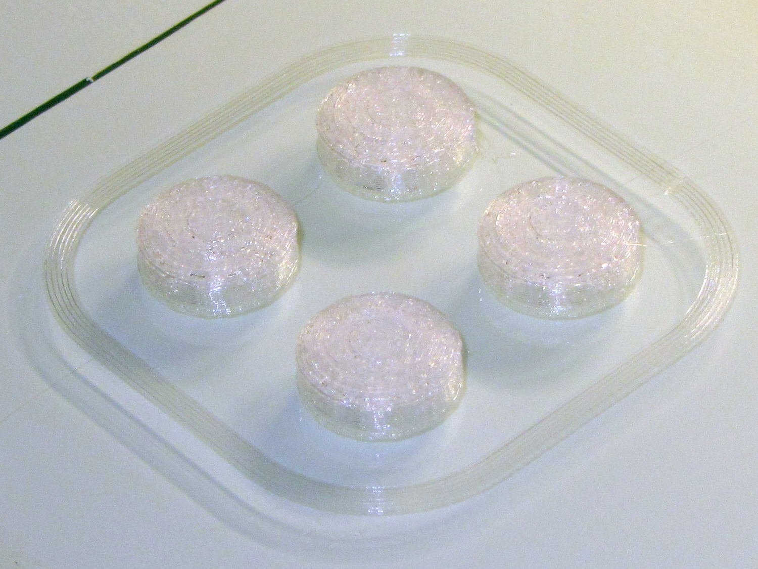
As with all small objects, building them four at a time gives the plastic in each one time to cool before slapping the next layer on top:
PTT Button – on platform
The hole in the cap is 0.2 mm oversize, which results in a snug press fit on the small ridges barely visible around the post in the first image:
PTT Button – rounded cap
Rather than compute the chord covering the surface, I just resized a sphere to twice the desired dome height (picked as 6 threads, just for convenience) and plunked it atop a cylinder. Remember to expand the sphere diameter by 1/cos(180/sides) to make it match the cylinder and force both to have the same number of sides.
This file contains hidden or bidirectional Unicode text that may be interpreted or compiled differently than what appears below. To review, open the file in an editor that reveals hidden Unicode characters.
Learn more about bidirectional Unicode characters
As part of setting the Makergear M2 up after The Great Cleanout, I ran off a set of thinwall calibration squares that showed the left rear corner was high by 0.12 mm: the square in that corner measured 2.88 mm, rather than the intended 3.0 mm. The walls were 0.43 mm, about 10% above the nominal 0.40 mm.
I tightened the rear platform screw by a bit under 1/12 turn, less than half a flat on the hex nut, and dialed the Extrusion Multiplier back by 10%. The next set of squares, set up for walls made of three parallel threads, came out with heights within 0.08 mm of each other and 1.15 mm thick (rather than the nominal 1.20 mm).
They’re 40 mm on a side, mostly to produce bigger handouts for the next show-n-tell:
Thinwall open box – array on platform – 3w 40 3.0
Letting it sit for a few days and running the same G-Code produced heights within 0.07 mm and wall thickness at 1.18, which I defined to be Good Enough.
Recent versions of Slic3r have been adjusting the various thread widths on the fly, as I’ve let everything except the basic extrusion width go with the default values. As a result, setting the wall width to 2 threads (0.80 mm) can produce an extremely thin third thread between the two perimeter threads that doesn’t extrude well. Making the wall three threads wide works much better:
Calibration Box – open – 3w 40 3.0
The slicing algorithms may be smart enough to make all the tricks I’ve learned completely obsolete; that’s fine with me!
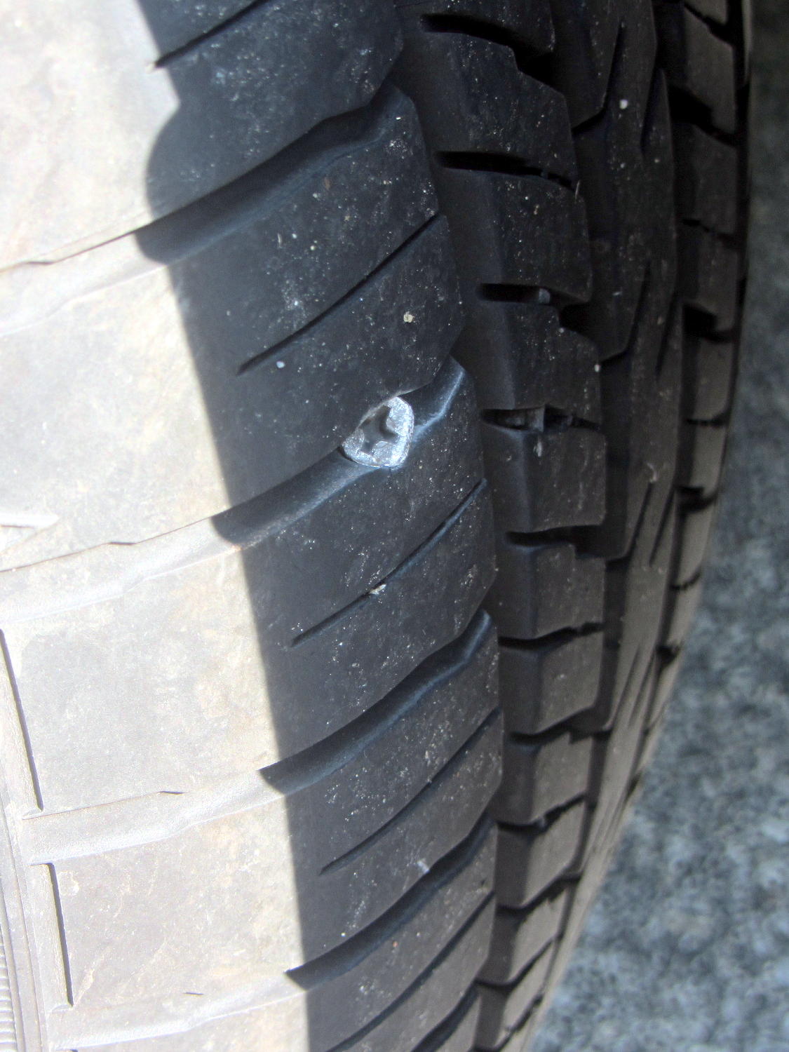
According to the Forester’s manual, the Tire Pressure Monitoring System kicks in after the car reaches 25 mph. It evidently takes a while to figure things out after that, because the TPMS light blinked on a mile from home on the way to Mary’s Vassar Farms garden. I pulled into the next parking lot, measured 20 psi in the left rear tire, then found this staring me in the eye:
Forester – left rear tire with screw
Well, that certainly simplified the diagnosis!
I unloaded two bags of shredded leaves and a pile of hoses, swapped in the (limited use, donut-style) spare tire, and continued the mission.
The TPMS light wasn’t on when I drove to Squidwrench the previous evening. Judging from the wear, that screw appeared during the various errands following our 800 mile road trip, which is good news of a sort, and depressurized the tire over the course of a day or two.
The receipt from the fix-it folks cautions that a plug is a temporary fix, because “the injury has compromised the integrity of the tire”. On the other paw, the Forester manual tells me “All four tires must be the same in terms of manufacturer, brand (tread pattern), construction, and size. You are advised to replace the tires with new ones that are identical to those fitted as standard equipment” and then provides a checklist:
When you replacing or installing tire(s), all four tires must be the same for following items.
(a) Size
(b) Circumference
(c) Speed symbol
(d) Load index
(e) Construction
(f) Manufacturer
(g) Brand (tread pattern)
(h) Degrees of wear
There’s absolutely no way to get an identical replacement tire, let alone one with the same tread wear, but I am so unready to replace all four tires after 12 k miles / 2 years.
After half a dozen years, the bearings in the blender impeller felt pretty bad:
Defunct blender bearings
I wiped everything clean, found the box containing the box containing the tube of bearings, packed the base with more silicone grease, reassembled everything in reverse order, and it’s all good again.
The first repair lasted for a year and the second for six, so I think overpacking the base with grease helped a lot. Maybe I’m getting better at ignoring horrible grinding sounds.
I can do this twice more, although the Jesus clip holding the shaft into the bearing stack definitely needs replacing.
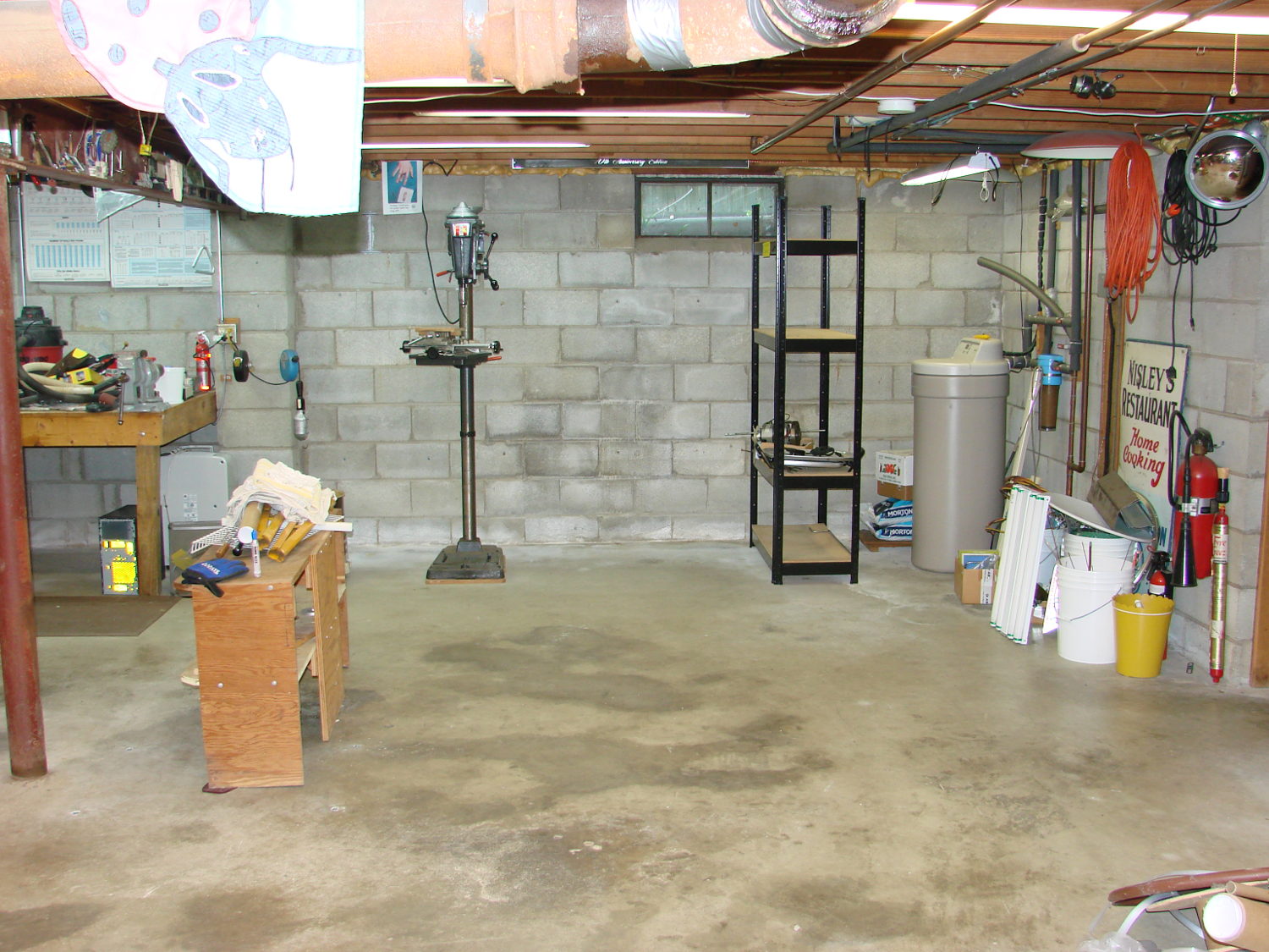
I now have some difficulty accomplishing what needs to be done:
Basement Shop – right
During the rest of May I must write a pair of columns, unpack / arrange / reinstall my remaining tools / parts / toys, endure a road trip to our Larval Engineer’s graduation (*), enjoy bicycling with my Lady, and surely repair a few odds-n-ends along the way.
I’ll generate occasional posts through June, after which things should be returning to what passes for normal around here…
(*) For reasons not relevant here, our Larval Engineer’s schedule includes a final co-op and wind-up semester after “graduation”. Perhaps she’s entering the Chrysalis phase of her development?
So I spent the last month (*) extracting the tools, parts, and stock I use on a regular basis, filling 20-ish boxes with stuff I wanted to keep:
Basement shop – right – before
After I moved all those boxes out of the way, three very industrious guys (and two teens who gradually got into the spirit of the thing) from MakerSmiths devoted all of a Saturday and a bit of Sunday morning converting an entire basement like that into this:
Basement Shop – right
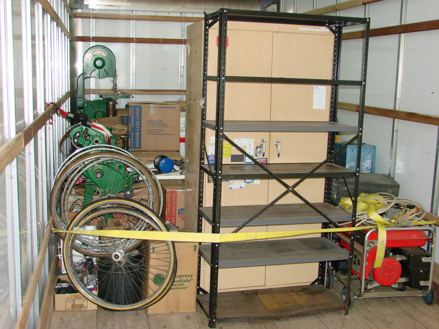
The stuff filled about 3/4 of the floor space in a pair of 26 foot box trucks:
Each truck had a snug 10,000 pound load limit and the stuff didn’t stack well:
The strap under the pile of metal, plus some plywood stiffeners, prevented it from running amok during transit. As long as they didn’t flip the truck, everything seemed well packed and cross-braced.
Only a few minor injuries; all’s well that ends well.
Alas, most of the spatial memory that let me find a tool or a part is now wrong; it’ll take a while to re-learn the new locations.
Back in high school, I designed and built a slide rule exposure calculator to improve my macro photographs:
Macrophotography Exposure Calculator – front
The base consists of three layers of thin cardboard glued together with Elmer’s Glue. The three slides have three layers of thinner white cardboard glued together, with offsets forming tongue-and-groove interlocks, topped with yellow paper for that true slide rule look:
Judging from the seams, I covered the hand-drawn scales with “invisible” matte-surface Scotch Tape. Worked well, if you ask me, and still looks pretty good:
Macrophotography Exposure Calculator – front – detail
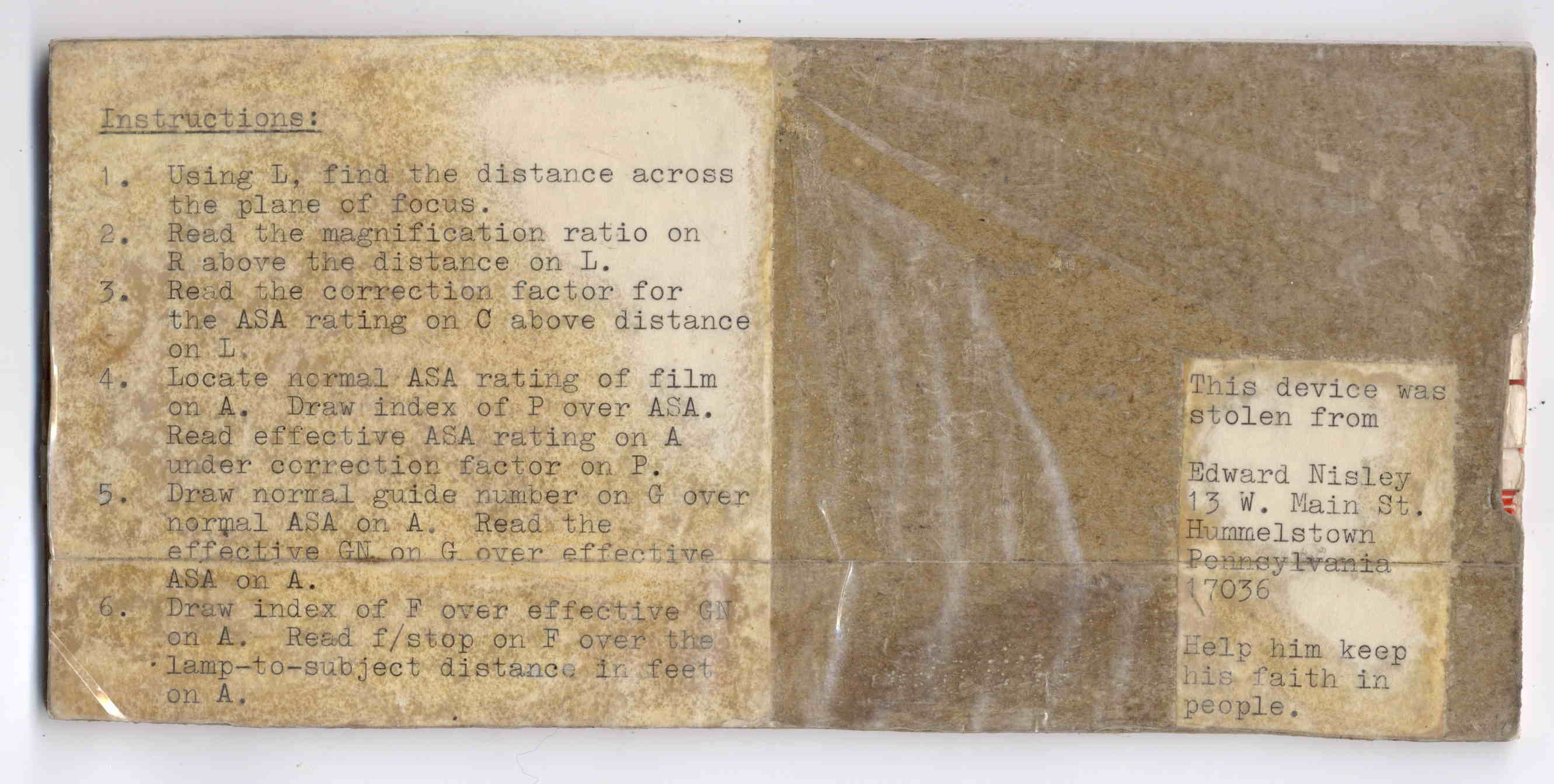
The reverse side carries instructions under a layer of packing tape (which hasn’t survived the test of time nearly as well), for anyone needing help:
The slides still move, albeit stiffly, and it might be usable.
I vaguely recall extension tubes on an early SLR, but memory fades after that. Getting the exposure settings close to the right value evidently posed something of a challenge and, given the cost of 35 mm film + development, it made sense to be careful.
Fortunately, even today’s low-end cameras make macro photography, at least for my simple needs, easy enough, with the camera handling the exposure calculations all by itself:
“… One of the most frightening things about your true nerd, for many people, is not that he’s socially inept — everybody’s been there — but rather his complete lack of embarrassment about it.”
“Which is kind of pathetic.”
“It was pathetic when they were in high school,” Randy says. “Now it’s something else. Something very different from pathetic.”
“What, then?”
“I don’t know. There is no word for it. You’ll see.”