Ya gotta have a lathe, so I replaced the big South Bend lathe with a Little Machine Shop 5200 7×16 Mini-lathe, because it’s toward the better end of the mini-lathe spectrum and, as Eks put it, it’s not the worst lathe you could own. Having had some experience with the Sherline’s cramped work envelope, the extra two inches of bed seemed like a Very Good Idea.
Ted Hansen’s articles on “Additions and Modifications to a Mini-Lathe” began in the September 2012 Home Shop Machinist and continue to this day, which hints at what’s needed to bring one of these puppies up to contemporary community standards. Unfortunately, HSM doesn’t offer a book or DVD with all the articles in one place; you can buy all the back issues or map the borders of your ethics.
Although the LMS 5200 incorporates many of Hansen’s tweaks (which was a powerful motivation for buying that package; I really don’t need a major diversion right now), it has plenty of room for improvement. In one of his earlier articles, he observes that you may be reluctant to dismantle the lathe, particularly the headstock and apron, because you’re afraid of disturbing the factory alignment. He then says something like “Don’t worry, that won’t be a problem.”
He’s absolutely correct.
Before putting the lathe in service, take it completely apart, wiping off the excess oil as you go, and reassemble it while paying attention to the obvious details. There’s nothing really breakable inside and the thing will run much better after a simple laying-on-of-hands “repair”.
The condition of the ways was … disappointing, even though I wasn’t expecting much. As nearly as I can tell, final way alignment, done by precision grinding or hand-scraping for spendy tools, consisted of a few passes with a hand-held angle grinder.
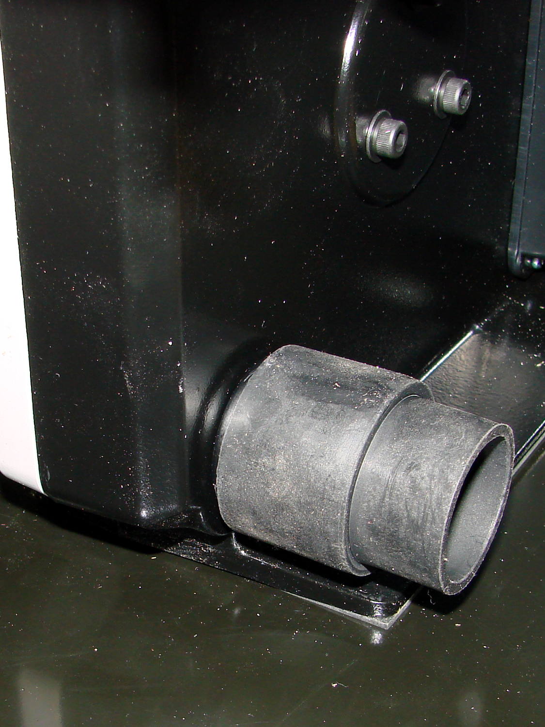
The tailstock doesn’t really need a sliding fit, because it operates while clamped to the bed; the flat way is rugged:
Its V-groove isn’t much better:

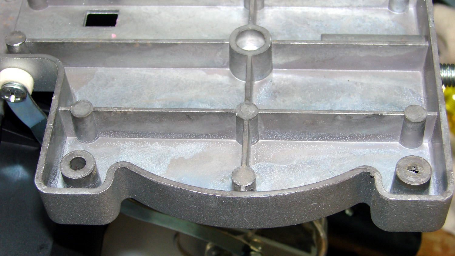
The compound ways are sliding joints, albeit with few points of contact:

The chromed (!) protractor dial has what Eks calls a “used car polish”: high shine over deep scratches.
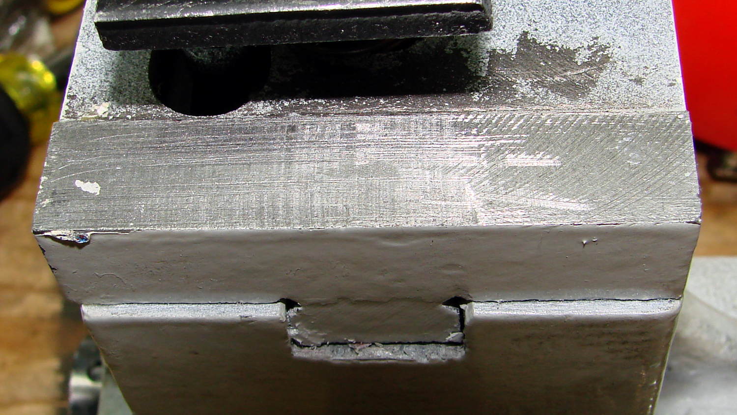
The cross-slide ways seem to be slightly concave, with a single contact point on the far left end and a few more on the right:

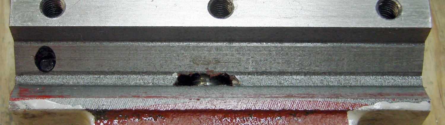
The carriage flat leaves much to be desired:

That red patch toward the left isn’t left-over scraping blue:
I have no intention of spending all the time required to hand-scrape those things, Moglice seems like overkill (and has an imposing minimum thickness), and Turcite requires reasonable surface finish (and adds considerable thickness, too).
I’m mildly temped to apply a thin layer of good ol’ JB Weld epoxy, just to fill in the valleys and improve the contact area, but not right now.