The Smell of Molten Projects in the Morning

Ed Nisley's Blog: Shop notes, electronics, firmware, machinery, 3D printing, laser cuttery, and curiosities. Contents: 100% human thinking, 0% AI slop.

Category: Machine Shop

Mechanical widgetry

  • Tour Easy Front Fender: Redux

    The front fender on Mary’s bike snapped loose while we were on our way for groceries, but my repair kit now once again includes a few feet of duct tape and we continued the mission:

    Tour Easy front fender - duct tape FTW
    Tour Easy front fender – duct tape FTW

    The final fracture seems to be just the little gray section amid the older fractures, so the Planet Bike clip was hanging on by a thread:

    Tour Easy front fender - broken clip
    Tour Easy front fender – broken clip

    Our bikes being equipped as alike as I can make them, another copy of the bracket I used on my bike sufficed:

    Tour Easy front fender - new bracket
    Tour Easy front fender – new bracket

    Stipulated: duct tape is déclassé, but it works better than anything else I’ve tried.

  • Dell Laptop Battery Teardown

    The defunct 18650 lithium cell  I used for the DSO150 power supplyprompted me to crack open a battery from a long-gone Dell laptop to see if any of its cells were in better condition:

    Dell laptop battery - case cracking
    Dell laptop battery – case cracking

    Yup, gently crushing it in a vise splits the case enough to work the Designated Prydriver around the joint, a process considerably simplified by the knowledge the case isn’t going back together again.

    Prying the top off reveals the cells and their connections:

    Dell laptop battery - circuitry
    Dell laptop battery – circuitry

    One of the cells had corroded, accounting for the pack’s failure:

    Dell laptop battery - corroded cell
    Dell laptop battery – corroded cell

    The others were undamaged, but had self-discharged down to about 1.5 V over the course of several years and refused to charge.

    The moral may be to tear the pack apart as soon as it fails, a point always easier to recognize in retrospect.

    So I taped the packs to prevent shorts and tossed them into the recycle box.

  • Chair Reupholstering

    We were tasked with replacing the foam cushion and seat covering on a pair of kitchen chairs. Removing the existing fabric seemed simple, until I pulled a dozen staples holding the cardboard cover to the bottom of the chair and exposed the fabric stapled to the MDF plate:

    Chair reupholstering - stapled fabric
    Chair reupholstering – stapled fabric

    That’s just part of one corner. Obviously, whoever built the chair wanted to be very very very sure the fabric didn’t come loose!

    Removing the staples from one corner produced a pile:

    Chair reupholstering - one corner of staples
    Chair reupholstering – one corner of staples

    Piling up all the staples from the other chair looked even more impressive:

    Chair reupholstering - staple pile
    Chair reupholstering – staple pile

    I fired maybe a third as many staples into the new fabric, which seems secure enough.

  • ShopVac vs. Samsung Vacuum Cleaner Bags

    While cleaning the filter in the 1 gallon ShopVac for the bandsaw and lathe, I found the last few bags from the never-sufficiently-to-be-damned and long-gone Samsung vacuum cleaner that seemed about the right size for upcycling:

    Shopvac vs Samsung vacuum cleaner bags - overview
    Shopvac vs Samsung vacuum cleaner bags – overview

    They’re a bit bulky:

    Shopvac vs Samsung vacuum cleaner bags - trial fit
    Shopvac vs Samsung vacuum cleaner bags – trial fit

    It’s surely not worth buying bags just to cut ’em up, but, with a stock on the shelf, why not?

  • Desk Drawer Stops

    The stops aligning the top two drawers of an old desk vanished, so I got the job of replacing them. They’re hammered into the wood frame:

    Drawer Stops - width measurement
    Drawer Stops – width measurement

    And stand up just enough to engage the back of the drawer face:

    Drawer Stops - height measurement
    Drawer Stops – height measurement

    Back in the Basement Laboratory Shop Wing, I harvested steel strips from a defunct PC case, rubber-hammered them flat, sharpened a cold chisel (un-hardened, so it always needs sharpening), and got to work:

    Drawer Stops - chiseled blanks
    Drawer Stops – chiseled blanks

    The pointy sides should have sharp edges, which you get for free with a chisel. You also get a bench full of little steel slivers perfectly suited for embedding in human flesh. Wearing eye protection is more than just a good idea, too.

    Introducing what will become the visible edges to Mr Disk Sander makes them marginally less hazardous:

    Drawer Stops - in progress
    Drawer Stops – in progress

    A slightly fuzzy picture of a test fit shows the stops should suffice:

    Drawer Stops - trial fit
    Drawer Stops – trial fit

    Which they did:

    Drawer Stops - installed
    Drawer Stops – installed

    Nobody will ever notice the blob of hot melt glue behind each one:

    Drawer Stops - glue blob
    Drawer Stops – glue blob

    Done!

  • Astable Multivibrator: NP-BX1 Base

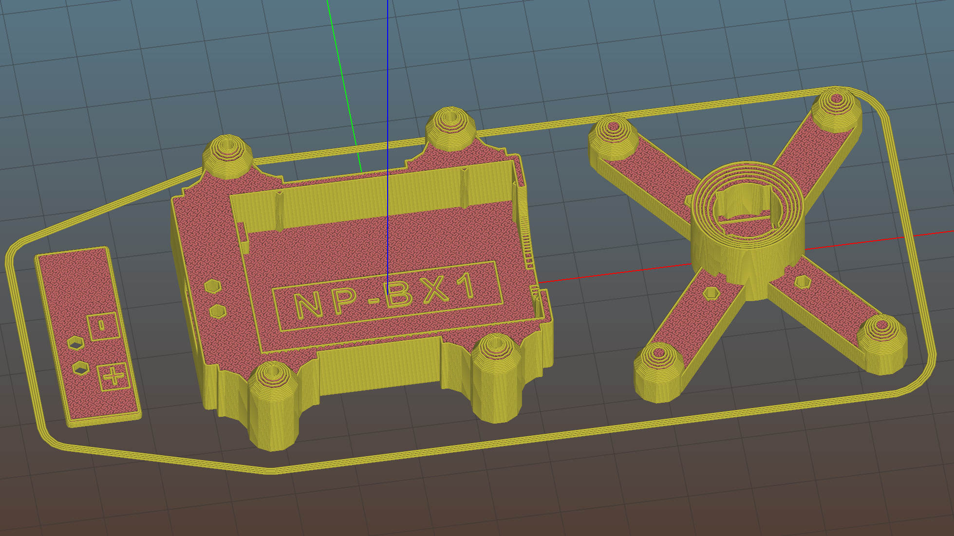
    Adapting the NP-BX1 battery holder to use SMT pogo pins worked well:

    NP-BX1 Holder - SMT pogo pins
    NP-BX1 Holder – SMT pogo pins

    The next step is to add sockets for those 14 AWG wires:

    NP-BX1 Battery Holder - Wire Posts - solid model
    NP-BX1 Battery Holder – Wire Posts – solid model

    Start by reaming / hand-drilling all the holes to their nominal size and cleaning out the pogo pin pocket.

    Solder wires to the pogo pins and thread them through the holder and lid:

    Astable - NP-BX1 holder - pogo pin soldering
    Astable – NP-BX1 holder – pogo pin soldering

    That’s nice, floppy silicone-insulated 24 AWG wire, which may be a bit too thick for this purpose.

    The pogo pins will, ideally, seat with the end of the body flush at the holder wall. Make it so:

    Astable - NP-BX1 holder - pogo pin protrusion
    Astable – NP-BX1 holder – pogo pin protrusion

    Dress the wires neatly into their pocket:

    Astable - NP-BX1 holder - pogo pin wiring
    Astable – NP-BX1 holder – pogo pin wiring

    Butter the bottom of the lid with epoxy, clamp in place, set it up for curing, then fill the recess:

    Astable - NP-BX1 base - curing
    Astable – NP-BX1 base – curing

    While it’s curing, make a soldering fixture for the 14 AWG wires:

    Astable - drilling strut soldering fixture
    Astable – drilling strut soldering fixture

    The holes are on 5 mm centers, in the expectation other battery holders will need different spacing.

    Solder it up and stick the wires into the base:

    Astable - NP-BX1 base - detail
    Astable – NP-BX1 base – detail

    Jam a battery in and It Just Works™:

    Astable - NP-BX1 3.8V - 20ma-div - cap V
    Astable – NP-BX1 3.8V – 20ma-div – cap V

    The traces:

    • Green = supply current at 20 mA/div
    • Yellow = LED driver transistor base voltage
    • Purple = other transistor collector voltage
    • White = base – collector voltage = capacitor voltage

    The measurement setup was a bit of a hairball:

    Astable - NP-BX1 base - current probe
    Astable – NP-BX1 base – current probe

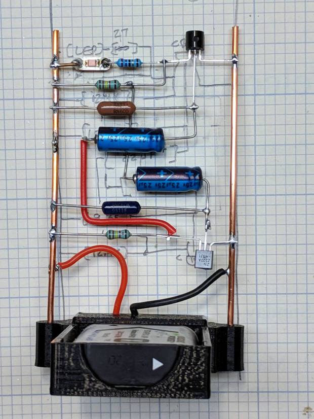
    For completeness, here’s the schematic-and-layout diagram behind the circuitry:

    Astable - NP-BX1 base - schematic
    Astable – NP-BX1 base – schematic

    I love it when a plan comes together!

    The OpenSCAD source code as a GitHub Gist:

    // Holder for Sony NP-BX1 Li-Ion battery
    // Ed Nisley KE4ZNU January 2013
    // 2018-11-15 Adapted for wire leads from 1.5 mm test pins, added upright wire bases
    // Layout options
    Layout = "Fit"; // Show Build Fit Case Lid Pins
    //- Extrusion parameters – must match reality!
    // Print with +2 shells and 3 solid layers
    ThreadThick = 0.25;
    ThreadWidth = 0.35;
    HoleWindage = 0.2;
    function IntegerMultiple(Size,Unit) = Unit * ceil(Size / Unit);
    Protrusion = 0.1; // make holes end cleanly
    inch = 25.4;
    BuildOffset = 3.0; // clearance for build layout
    Gap = 2.0; // separation for Fit parts
    //- Basic dimensions
    WallThick = 4*ThreadWidth; // holder sidewalls
    BaseThick = 6*ThreadThick; // bottom of holder to bottom of battery
    TopThick = 6*ThreadThick; // top of battery to top of holder
    //- Battery dimensions – rationalized from several samples
    // Coordinate origin at battery contact face with key openings below contacts
    Battery = [43.0,30.0,9.5]; // X = length, Y = width, Z = thickness
    Contacts = [[-0.75,6.0,6.2],[-0.75,16.0,6.2]]; // relative to battery edge, front, and bottom
    ContactOC = Contacts[1].y – Contacts[0].y;
    ContactCenter = Contacts[0].y + ContactOC/2;
    KeyBlocks = [[1.75,3.70,2.90],[1.75,3.60,2.90]]; // recesses in battery face set X position
    //- Pin dimensions
    ID = 0;
    OD = 1;
    LENGTH = 2;
    PinShank = [1.5,2.0,6.5]; // shank, flange, compressed length
    PinFlange = [1.5,2.0,0.5]; // flange, length included in PinShank
    PinTip = [0.9,0.9,2.5]; // extended spring-loaded tip
    PinChannel = PinFlange[LENGTH] + 0.5; // cut behind flange for solder overflow
    PinRecess = 3.0; // recess behind pin flange end for epoxy fill
    echo(str("Contact tip dia: ",PinTip[OD]));
    echo(str(" .. shank dia: ",PinShank[ID]));
    OverTravel = 0.5; // space beyond battery face at X origin
    //- Holder dimensions
    GuideRadius = ThreadWidth; // friction fit ridges
    GuideOffset = 7; // from compartment corners
    ThumbRadius = 10.0; // thumb opening at end of battery
    CornerRadius = 3*ThreadThick; // nice corner rounding
    CaseSize = [Battery.x + PinShank[LENGTH] + OverTravel + PinRecess + GuideRadius + WallThick,
    Battery.y + 2*WallThick + 2*GuideRadius,
    Battery.z + BaseThick + TopThick];
    CaseOffset = [-(PinShank[LENGTH] + OverTravel + PinRecess),-(WallThick + GuideRadius),0]; // position around battery
    LidOverhang = 2.0; // over top of battery for retention
    LidSize = [-CaseOffset.x + LidOverhang,CaseSize.y,TopThick];
    LidOffset = [0.0,CaseOffset.y,0];
    //- Wire struts
    StrutDia = 1.6; // AWG 14 = 1.6 mm
    StrutOC = 45;
    StrutSides = 3*4;
    StrutBase = [StrutDia,StrutDia + 4*WallThick,CaseSize.z – TopThick]; // ID = wire, OD=buildable
    //———————-
    // Useful routines
    module PolyCyl(Dia,Height,ForceSides=0) { // based on nophead's polyholes
    Sides = (ForceSides != 0) ? ForceSides : (ceil(Dia) + 2);
    FixDia = Dia / cos(180/Sides);
    cylinder(r=(FixDia + HoleWindage)/2,h=Height,$fn=Sides);
    }
    //——————-
    //– Guides for tighter friction fit
    module Guides() {
    translate([GuideOffset,-GuideRadius,0])
    PolyCyl(2*GuideRadius,(Battery.z – Protrusion),4);
    translate([GuideOffset,(Battery.y + GuideRadius),0])
    PolyCyl(2*GuideRadius,(Battery.z – Protrusion),4);
    translate([(Battery.x – GuideOffset),-GuideRadius,0])
    PolyCyl(2*GuideRadius,(Battery.z – Protrusion),4);
    translate([(Battery.x – GuideOffset),(Battery.y + GuideRadius),0])
    PolyCyl(2*GuideRadius,(Battery.z – Protrusion),4);
    translate([(Battery.x + GuideRadius),GuideOffset/2,0])
    PolyCyl(2*GuideRadius,(Battery.z – Protrusion),4);
    translate([(Battery.x + GuideRadius),(Battery.y – GuideOffset/2),0])
    PolyCyl(2*GuideRadius,(Battery.z – Protrusion),4);
    }
    //– Contact pins
    // Rotated to put them in their natural oriention
    // Aligned to put tip base / end of shank at Overtravel limit
    module PinShape() {
    translate([-(PinShank[LENGTH] + OverTravel),0,0])
    rotate([0,90,0])
    rotate(180/6)
    union() {
    PolyCyl(PinTip[OD],PinShank[LENGTH] + PinTip[LENGTH],6);
    PolyCyl(PinShank[ID],PinShank[LENGTH] + Protrusion,6); // slight extension for clean cuts
    PolyCyl(PinFlange[OD],PinFlange[LENGTH],6);
    }
    }
    // Position pins to put end of shank at battery face
    // Does not include recess access into case
    module PinAssembly() {
    union() {
    for (p = Contacts)
    translate([0,p.y,p.z])
    PinShape();
    translate([-(PinShank[LENGTH] + OverTravel) + PinChannel/2, // solder space
    ContactCenter,
    Contacts[0].z])
    cube([PinChannel,(Contacts[1].y – Contacts[0].y),PinFlange[OD]],center=true);
    for (j=[-1,1]) // wire channels
    translate([-(PinShank[LENGTH] + OverTravel – PinChannel/2),
    j*ContactOC/4 + ContactCenter,
    Contacts[0].z – PinFlange[OD]/2])
    rotate(180/6)
    PolyCyl(PinFlange[OD],CaseSize.z,6);
    }
    }
    //– Case with origin at battery corner
    module Case() {
    difference() {
    union() {
    difference() {
    union() {
    translate([(CaseSize.x/2 + CaseOffset.x), // basic case shape
    (CaseSize.y/2 + CaseOffset.y),
    (CaseSize.z/2 – BaseThick)])
    hull()
    for (i=[-1,1], j=[-1,1], k=[-1,1])
    translate([i*(CaseSize.x/2 – CornerRadius),
    j*(CaseSize.y/2 – CornerRadius),
    k*(CaseSize.z/2 – CornerRadius)])
    sphere(r=CornerRadius/cos(180/8),$fn=8); // cos() fixes undersize spheres!
    hull() // wire strut bases
    for (j=[-1,1])
    translate([0,j*StrutOC/2 + Battery.y/2,-BaseThick])
    rotate(180/StrutSides)
    cylinder(d=StrutBase[OD],h=StrutBase[LENGTH],$fn=StrutSides);
    translate([0,Battery.y/2,StrutBase[LENGTH]/2 – BaseThick])
    cube([2*StrutBase[OD],StrutOC,StrutBase[LENGTH]],center=true);
    }
    translate([-OverTravel,-GuideRadius,0])
    cube([(Battery.x + GuideRadius + OverTravel),
    (Battery.y + 2*GuideRadius),
    (Battery.z + Protrusion)]); // battery space
    }
    Guides(); // improve friction fit
    translate([-OverTravel,-GuideRadius,0]) // battery keying blocks
    cube(KeyBlocks[0] + [OverTravel,GuideRadius,0],center=false);
    translate([-OverTravel,(Battery.y – KeyBlocks[1].y),0])
    cube(KeyBlocks[1] + [OverTravel,GuideRadius,0],center=false);
    }
    translate([2*CaseOffset.x, // battery top access
    (CaseOffset.y – Protrusion),
    Battery.z])
    cube([2*CaseSize.x,(CaseSize.y + 2*Protrusion),(TopThick + Protrusion)]);
    if (false)
    translate([(CaseOffset.x – Protrusion), // battery insertion allowance
    (CaseOffset.y – Protrusion),
    Battery.z])
    cube([(CaseSize.x + 2*Protrusion),(CaseSize.y + 2*Protrusion),(TopThick + Protrusion)]);
    for (j=[-1,1]) // strut wires
    translate([0,j*StrutOC/2 + Battery.y/2,-(BaseThick + Protrusion)])
    PolyCyl(StrutBase[ID],StrutBase[LENGTH] + 2*Protrusion,6);
    for (i=[-1,1], j=[-1,1])
    translate([i*StrutBase[OD],j*StrutOC/2 + Battery.y/2,-(BaseThick + Protrusion)])
    rotate(180/StrutSides)
    PolyCyl(StrutBase[OD],StrutBase[LENGTH] + 2*Protrusion,StrutSides);
    translate([(Battery.x – Protrusion), // remove thumb notch
    (CaseSize.y/2 + CaseOffset.y),
    (ThumbRadius)])
    rotate([90,0,0])
    rotate([0,90,0])
    cylinder(r=ThumbRadius,
    h=(WallThick + GuideRadius + 2*Protrusion),
    $fn=22);
    PinAssembly();
    translate([CaseOffset.x + PinRecess + Protrusion,(Contacts[1].y + Contacts[0].y)/2,Contacts[0].z])
    translate([-PinRecess,0,0])
    cube([2*PinRecess,
    (Contacts[1].y – Contacts[0].y + PinFlange[OD]),
    2*PinFlange[OD]],center=true);
    }
    }
    // Lid position offset to match case
    module Lid() {
    difference() {
    translate([-LidSize.x/2 + LidOffset.x + LidOverhang,LidSize.y/2 + LidOffset.y,0])
    difference() {
    hull()
    for (i=[-1,1], j=[-1,1], k=[-1,1])
    translate([i*(LidSize.x/2 – CornerRadius),
    j*(LidSize.y/2 – CornerRadius),
    k*(LidSize.z – CornerRadius)]) // double thickness for flat bottom
    sphere(r=CornerRadius,$fn=8);
    translate([0,0,-LidSize.z/2]) // remove bottom
    cube([(LidSize.x + 2*Protrusion),(LidSize.y + 2*Protrusion),LidSize.z],center=true);
    translate([LidSize.x/8,0,0])
    cube([LidSize.x/4,0.75*LidSize.y,4*ThreadThick],center=true); // epoxy recess
    }
    translate([0,0,-(Contacts[0].z + PinFlange[OD])]) // punch wire holes
    PinAssembly();
    }
    }
    //——————-
    // Build it!
    if (Layout == "Case")
    Case();
    if (Layout == "Lid")
    Lid();
    if (Layout == "Pins") {
    color("Silver",0.5)
    PinShape();
    PinAssembly();
    }
    if (Layout == "Show") { // reveal pin assembly
    difference() {
    Case();
    translate([(CaseOffset.x – Protrusion),
    Contacts[1].y,
    Contacts[1].z])
    cube([(-CaseOffset.x + Protrusion),
    CaseSize.y,
    (CaseSize.z – Contacts[0].z + Protrusion)]);
    translate([(CaseOffset.x – Protrusion),
    (CaseOffset.y – Protrusion),
    0])
    cube([(-CaseOffset.x + Protrusion),
    Contacts[0].y + Protrusion – CaseOffset.y,
    CaseSize.z]);
    }
    translate([0,0,Battery.z + Gap])
    Lid();
    color("Silver",0.15)
    PinAssembly();
    }
    if (Layout == "Build") {
    translate([-(CaseSize.x/2 + CaseOffset.x),-(CaseOffset.y – BuildOffset),BaseThick])
    Case();
    translate([CaseSize.x/2,-LidSize.x/2,0])
    rotate(90)
    Lid();
    }
    if (Layout == "Fit") {
    Case();
    translate([0,0,(Battery.z + Gap)])
    Lid();
    color("Silver",0.25)
    PinAssembly();
    }
  • Six Gallon Can Lid Adapter to Platform Bird Feeder

    A House Finch suffering from Finch Eye Disease prompted me to sterilize our feeder, which meant providing a temporary feeder to keep the birds flying. Having an abundance of lids from six gallon plastic cans / buckets, this made sense:

    Can Lid Feeder - installed
    Can Lid Feeder – installed

    Which required an adapter betwixt pole and lid:

    Can Lid Feeder - assembled
    Can Lid Feeder – assembled

    Which requires a bit of solid modeling:

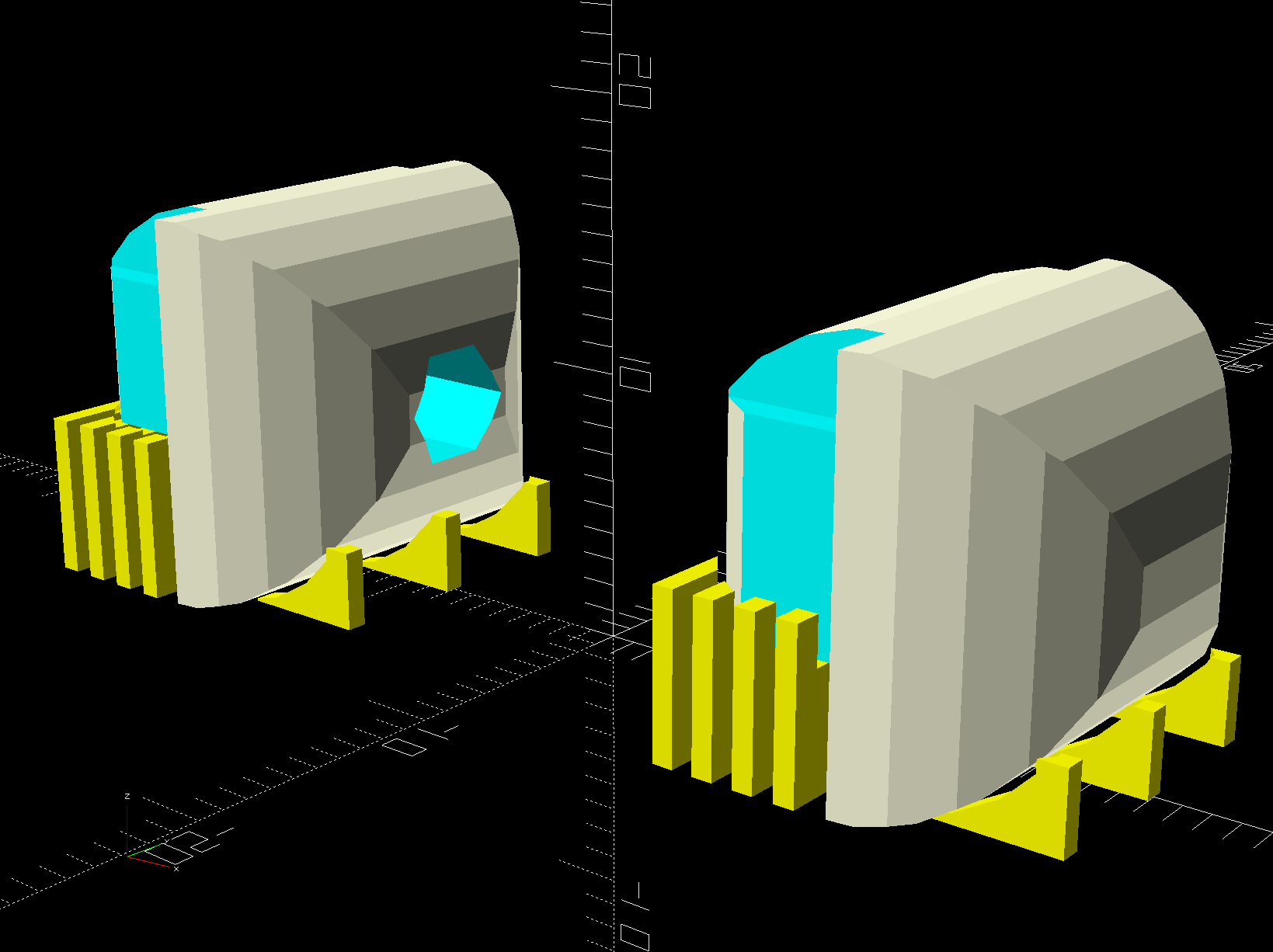
    Can Lid Platform Feeder Mount - solid model - bottom
    Can Lid Platform Feeder Mount – solid model – bottom

    The lids have a central boss, presumably for stiffening, so the model includes a suitable recess:

    Can Lid Platform Feeder Mount - solid model - support structure
    Can Lid Platform Feeder Mount – solid model – support structure

    As usual, automatically generated support fills the entire recess, so I designed a minimal support structure into the model and cracked it out with very little effort:

    Can Lid Feeder - support structure
    Can Lid Feeder – support structure

    The tangle off to the right comes from a bridge layer with a hole in the middle, which never works well even with support:

    Can Lid Platform Feeder Mount - Slic3r - bridge layer
    Can Lid Platform Feeder Mount – Slic3r – bridge layer

    Didn’t bother the birds in the least, though, so it’s all good.

    I loves me my 3D printer …

    The OpenSCAD source code as a GitHub Gist:

    // Adapter from steel pole to 5 gallon plastic can lid
    // Turns the lid into a improvised platform feeder
    // Ed Nisley – KE4ZNU – 2018-11
    Layout = "Build"; // Show Build
    ThreadThick = 0.25;
    ThreadWidth = 0.40;
    HoleWindage = 0.2;
    function IntegerMultiple(Size,Unit) = Unit * ceil(Size / Unit);
    Protrusion = 0.1; // make holes end cleanly
    // Sizes
    ID = 0;
    OD = 1;
    LENGTH = 2;
    Wall = 10; // minimum thickness or width for anything
    Boss = [15,50,9]; // central boss on lie
    Flange = [50,110,Boss[LENGTH] + Wall];
    echo(Boss);
    echo(Flange);
    Pole = [(23.5 + 4*HoleWindage),26,45]; // small end of steel pole
    Screw = [5.0,8.0,25.0]; // 5 mm or 10-32
    ScrewOC = 80; // lid mounting screws
    NumScrews = 3;
    NumSides = NumScrews*2*4;
    $fn = NumSides;
    //———————-
    // Useful routines
    module PolyCyl(Dia,Height,ForceSides=0) { // based on nophead's polyholes
    Sides = (ForceSides != 0) ? ForceSides : (ceil(Dia) + 2);
    FixDia = Dia / cos(180/Sides);
    cylinder(r=(FixDia + HoleWindage)/2,h=Height,$fn=Sides);
    }
    //———————-
    // Build it
    module Bracket() {
    difference() {
    union() {
    rotate(180/(NumSides/2)) {
    cylinder(d=Flange[OD],h=Flange[LENGTH],$fn=NumSides/2); // fewer sides is OK
    cylinder(d=Pole[OD] + 2*Wall,h=Pole[LENGTH] + Flange[LENGTH],$fn=NumSides/2);
    }
    }
    translate([0,0,-Protrusion])
    rotate(180/NumSides)
    cylinder(d=Boss[OD],h=Boss[LENGTH] + Protrusion,$fn=NumSides);
    translate([0,0,-Protrusion])
    rotate(180/NumSides)
    cylinder(d=Pole[ID],h=2*(Pole[LENGTH] + Flange[LENGTH]),$fn=NumSides);
    for (i=[0:NumScrews-1])
    rotate(i*(360/NumScrews))
    translate([ScrewOC/2,0,-Protrusion])
    PolyCyl(Screw[ID],2*Flange[LENGTH],6);
    }
    }
    module Support() {
    NumRibs = NumSides/2;
    Rib = [0.95*(Boss[OD] – Pole[ID])/2,2*ThreadWidth,Boss[LENGTH] – ThreadThick];
    color("Yellow") {
    for (i=[0:NumRibs-1]) {
    a = i*360/NumRibs;
    rotate(a)
    translate([Pole[ID]/2 + Rib.x/2,0,Rib.z/2])
    cube(Rib,center=true);
    }
    rotate(180/NumSides)
    difference() {
    cylinder(d=Pole[ID] + 10*ThreadWidth,h=1*ThreadThick,$fn=NumSides);
    translate([0,0,-Protrusion])
    cylinder(d=Pole[ID],h=Rib.z + 2*Protrusion,$fn=NumSides);
    }
    }
    }
    if (Layout == "Show")
    Bracket();
    if (Layout == "Build") {
    Bracket();
    Support();
    }