|
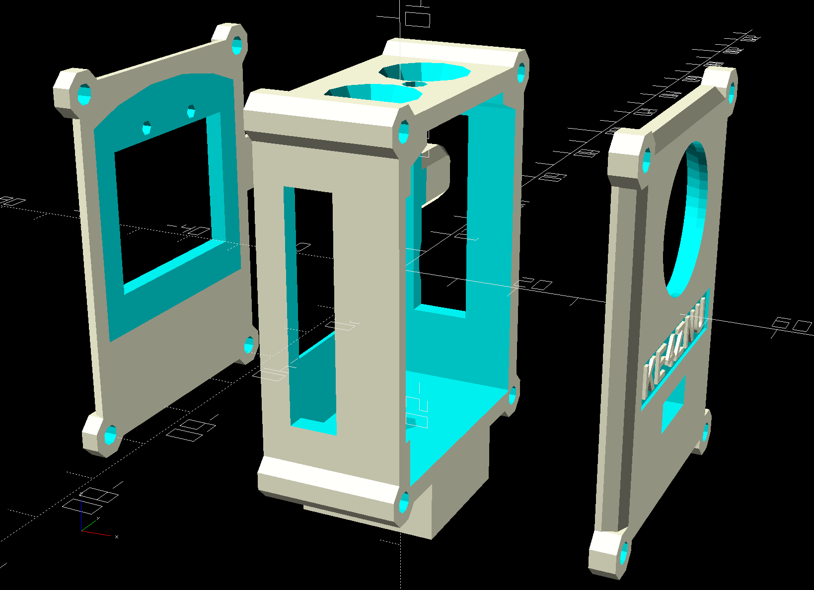
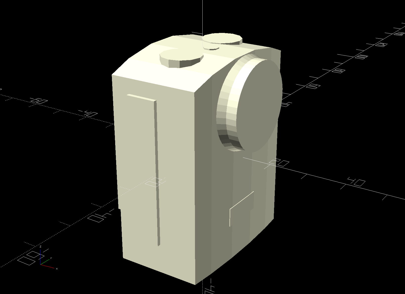
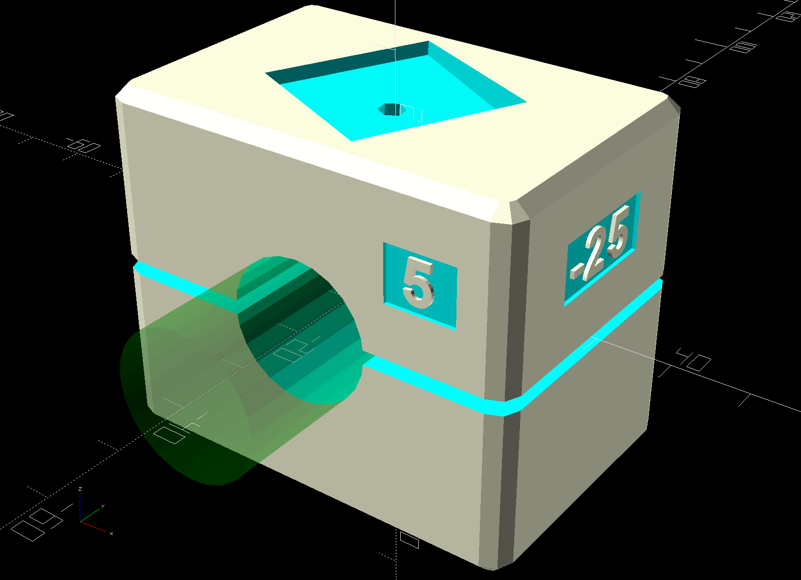
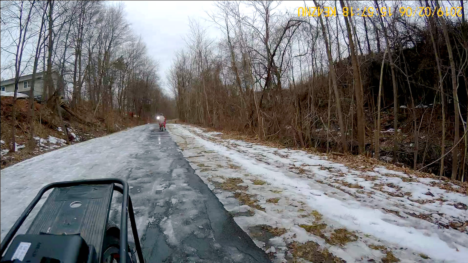
// SJCAM M20 Camera Mount for Tour Easy seat back rail |
|
// Ed Nisley – KE4ZNU |
|
// 2019-02 |
|
|
|
/* [Layout Options] */ |
|
|
|
Layout = "Fit"; // [Show,Fit,Build] |
|
|
|
Part = "Shell"; // [Cradle,Shell,Clamp,ShellSections,M20,Interposer,Battery,Buttons] |
|
|
|
LookAngle = [0,5,-25]; // camera angle, looking backwards |
|
|
|
|
|
/* [Extrusion Parameters] */ |
|
|
|
ThreadWidth = 0.40; |
|
ThreadThick = 0.25; |
|
|
|
HoleWindage = 0.2; |
|
|
|
Protrusion = 0.1; |
|
|
|
//—– |
|
// Dimensions |
|
|
|
/* [Hidden] */ |
|
|
|
ID = 0; |
|
OD = 1; |
|
LENGTH = 2; |
|
|
|
ClampScrew = [5.0,10.0,50.0]; // ID=thread OD=washer LENGTH=total |
|
ClampInsert = [5.0,7.5,10.5]; // brass insert |
|
|
|
MountScrew = [3.0,7.0,23]; // ID=thread OD=washer LENGTH=tune to fit clamp arch |
|
MountInsert = [3.0,4.95,8.0]; // ID=screw OD, OD=knurl dia |
|
|
|
EmbossDepth = 2*ThreadThick + Protrusion; // recess depth + Protrusion beyond surface |
|
|
|
DebossHeight = EmbossDepth; // text height + Protrusion into part |
|
|
|
Projection = 10; // stick-out to punch through shell sides & suchlike |
|
|
|
SupportColor = "Yellow"; |
|
FadeColor = "Green"; |
|
FadeAlpha = 0.25; |
|
|
|
//—– |
|
// Useful routines |
|
|
|
function IntegerMultiple(Size,Unit) = Unit * ceil(Size / Unit); |
|
|
|
module PolyCyl(Dia,Height,ForceSides=0) { // based on nophead's polyholes |
|
|
|
Sides = (ForceSides != 0) ? ForceSides : (ceil(Dia) + 2); |
|
|
|
FixDia = Dia / cos(180/Sides); |
|
|
|
cylinder(r=(FixDia + HoleWindage)/2, |
|
h=Height, |
|
$fn=Sides); |
|
} |
|
|
|
//—– |
|
// M20 Camera |
|
// Looks backwards from seat = usual right-hand coordinates work fine |
|
// X parallel to bike frame, Y parallel to seat strut, Z true vertical |
|
|
|
M20 = [24.5,40.5,54.0]; |
|
|
|
M20tm = 4.0; // chord height at top of case |
|
M20tr = (pow(M20tm,2) + pow(M20.y,2)/4) / (2*M20tm); // … radius |
|
echo(str("Top radius: ",M20tr)); |
|
|
|
M20TopSides = 3*3*4; |
|
echo(str(" … sides: ",M20TopSides)); |
|
|
|
M20fm = 1.0; // chord height at front of case |
|
M20fr = (pow(M20fm,2) + pow(M20.y,2)/4) / (2*M20fm); // … radius |
|
echo(str("Front radius: ",M20fr)); |
|
|
|
M20FrontSides = ceil(M20fr / M20tr * M20TopSides); // make arc sides match up |
|
echo(str(" … sides: ",M20FrontSides)); |
|
|
|
Lens = [19.0,22.5,5.5]; // ID=optical element, OD=tube |
|
LensBezel = [23.0,24.5,2.5]; // ID=lens tube, OD=bezel |
|
LensOffset = [-M20fm,0,41.5]; // bottom of case to lens centerline |
|
|
|
LensCap = [Lens[OD],24.5,4.5]; // silicone lens cap |
|
|
|
Spkr = [0.75,M20.y,14.3]; // speaker recess below LCD |
|
|
|
Switch = [8.0,1.0,38.0]; // selection switches |
|
SwitchOffset = [9.0,0,0]; // from rear to center of switches |
|
|
|
Jack = [10.0,0.1,36.0]; // jack and MicroSD card access, slightly enlarged |
|
JackOffset = [10.0,0,30.0]; // rear, bottom to center of jack block |
|
|
|
USB = [JackOffset.x – Jack.x/2,20.0,10.0]; // strut under USB plug |
|
USBOffset = [0,0,33.5]; // bottom to center of jack |
|
|
|
SDCard = [2.0,0.1,12.0]; // SD Card slot |
|
SDOffset = [9.0,0,20.0]; // bottom, rear to center of slot |
|
|
|
Button = [8.5,10.5,M20tm]; // ID = button, OD = bezel |
|
ButtonOC = 18.0; // on-center Y separation, assume X centered |
|
|
|
Screen = [0.1,31,24]; // LCD on rear face |
|
ScreenOffset = [0,0,33]; |
|
|
|
BarLEDs = [0.1 + M20fm,12.0,5.0]; // Bar LEDs on front face |
|
BarLEDsOffset = [-M20fm,0,12.5]; |
|
|
|
PwrLED = [3.5,3.5,0.1 + M20tm]; // power LED on top |
|
PwrLEDOffset = [2.5,0,0]; |
|
|
|
RearLEDs = [1.0,2.0,0.1]; // charge and power LED openings above LCD |
|
RearLEDsOffset = [0,13.0/2,M20tm + 3.0]; // .. from top center of case |
|
|
|
module Buttons(KO) { |
|
for (j = [-1,1]) |
|
translate([0,j*ButtonOC/2,0]) { |
|
cylinder(d=Button[OD],h=Button[LENGTH],$fn=12); |
|
if (KO) |
|
translate([0,0,M20tm]) |
|
cylinder(d1=Button[OD],d2=1.5*Button[OD],h=Button.z,$fn=12); |
|
} |
|
} |
|
|
|
module M20Shape(Knockout = false) { |
|
|
|
difference() { |
|
intersection() { |
|
translate([0,0,M20.z/2 – M20tr]) // top curve |
|
rotate([0,90,0]) rotate(180/M20TopSides) |
|
cylinder(r=M20tr,h=2*(M20.x + Protrusion),$fn=M20TopSides,center=true); |
|
translate([M20.x/2 – M20fr,0,0]) |
|
rotate(180/M20FrontSides) |
|
cylinder(r=M20fr,h=2*M20.z,$fn=M20FrontSides,center=true); |
|
cube(M20,center=true); |
|
} |
|
translate([Spkr.x/2 – M20.x/2 – Protrusion,0,Spkr.z/2 – Protrusion/2 – M20.z/2]) |
|
cube(Spkr + [Protrusion,2*Protrusion,Protrusion],center=true); |
|
} |
|
|
|
translate([M20.x/2,0,-M20.z/2] + LensOffset) |
|
rotate([0,90,0]) |
|
cylinder(d=Lens[OD] + HoleWindage,h=(Knockout ? Projection : Lens[LENGTH]),$fn=4*4*3,center=false); |
|
|
|
translate([M20.x/2 + M20fm/2,0,-M20.z/2] + LensOffset) // lens bezel |
|
rotate([0,90,0]) |
|
cylinder(d1=LensBezel[OD],d2=Lens[OD],h=LensBezel[LENGTH],$fn=4*4*3,center=false); |
|
|
|
translate([-M20.x/2 + SwitchOffset.x, // side switches |
|
-(Switch.y + M20.y – Protrusion)/2, |
|
0]) |
|
cube(Switch + [0,Protrusion,0] + (Knockout ? [0,Projection,0] : [0,0,0]),center=true); |
|
|
|
if (Knockout) |
|
translate([(M20.x/2 – M20fm)/2,-M20.y/2,0]) // side switch slide-in clearance |
|
cube([M20.x/2 – M20fm,2*Switch.y,Switch.z],center=true); |
|
|
|
translate([-M20.x/2 + JackOffset.x, |
|
(Jack.y + M20.y – Protrusion)/2, |
|
JackOffset.z – M20.z/2]) |
|
cube(Jack + [0,Protrusion,0] + (Knockout ? [0,Projection,0] : [0,0,0]),center=true); |
|
|
|
translate([0,0,M20.z/2 – M20tm]) // top control buttons |
|
Buttons(Knockout); |
|
|
|
if (Knockout) |
|
translate([(M20.x – M20fm)/4,0,M20.z/2 – M20tm + Button[LENGTH]/2]) // slide-in button clearance |
|
cube([(M20.x – M20fm)/2,ButtonOC + Button[OD],Button[LENGTH]],center=true); |
|
|
|
translate([-(M20.x + Screen.x – Protrusion)/2,0,-M20.z/2] + ScreenOffset) |
|
cube(Screen + [Protrusion,0,0] + (Knockout ? [Projection,0,0] : [0,0,0]),center=true); |
|
|
|
for (j = [-1,1]) |
|
translate([-M20.x/2 + Protrusion,j*RearLEDsOffset.y,M20.z/2 – RearLEDsOffset.z]) |
|
rotate([0,-90,0]) rotate(180/6) |
|
PolyCyl(RearLEDs[OD],Knockout ? Projection : RearLEDs[LENGTH],6); |
|
|
|
translate([M20.x/2 + BarLEDs.x/2,0,-M20.z/2] + BarLEDsOffset) |
|
cube(BarLEDs + (Knockout ? [Projection,0,0] : [0,0,0]),center=true); |
|
|
|
translate([0,0,M20.z/2 – M20tm] + PwrLEDOffset) |
|
rotate(180/8) |
|
PolyCyl(PwrLED[OD],(Knockout ? Projection : PwrLED[LENGTH]),8); |
|
|
|
if (Knockout) { |
|
translate([0,0,-M20.z/2]) |
|
rotate([180,0,0]) { // mounting screw |
|
PolyCyl(MountScrew[ID],MountScrew[LENGTH],6); |
|
translate([0,0,MountScrew[LENGTH] – Protrusion]) |
|
PolyCyl(MountScrew[OD],MountScrew[ID] + 4*ThreadThick,6); // SHCS head is about 1 ID long |
|
} |
|
|
|
translate([0,0,-(M20.z/2 + MountInsert[LENGTH] + 4*ThreadWidth – Protrusion)]) |
|
PolyCyl(MountInsert[OD],MountInsert[LENGTH] + 4*ThreadWidth,6); // insert inside Interposer |
|
} |
|
|
|
} |
|
|
|
//—– |
|
// Shell |
|
// Wraps around camera |
|
|
|
NomWall = 3.0; |
|
|
|
ShellWall = [IntegerMultiple(NomWall,ThreadThick), |
|
IntegerMultiple(NomWall,ThreadWidth), |
|
IntegerMultiple(NomWall,ThreadWidth)]; |
|
ShellRadius = ShellWall.x; |
|
ShellSides = 8; |
|
|
|
ShellOA = M20 + 2*ShellWall; |
|
echo(str("Shell OA: ",ShellOA)); |
|
|
|
Interposer = [M20.x – M20fm,M20.x – M20fm,10.0]; // if you can't be smart, be square |
|
|
|
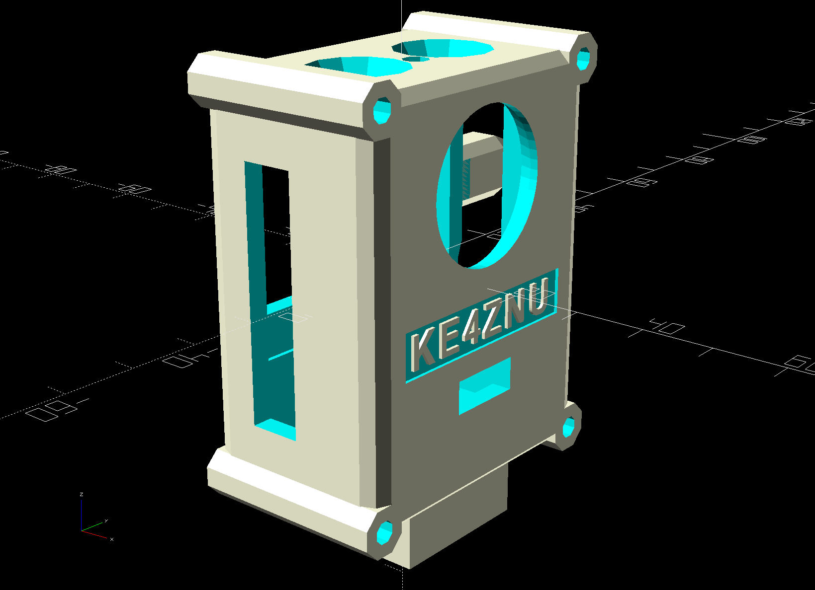
module Shell() { |
|
|
|
Screw = [3.0,6.75,30]; // ID=thread OD=washer LENGTH |
|
ScrewClear = 1.0; // additional washer clearance |
|
ScrewSides = 8; |
|
|
|
ScrewOC = M20 + [0,Screw[ID]/cos(180/ScrewSides),Screw[ID]/cos(180/ScrewSides)]; // use PolyCyl hole dia, ignore .x value |
|
|
|
difference() { |
|
union() { |
|
hull() |
|
for (i=[-1,1], j=[-1,1], k=[-1,1]) |
|
translate([i*(ShellOA.x – 2*ShellRadius)/2, |
|
j*(ShellOA.y – 2*ShellRadius)/2, |
|
k*(ShellOA.z – 2*ShellRadius)/2]) |
|
sphere(r=ShellRadius/cos(180/ShellSides),$fn=ShellSides); // fix low-poly approx radius |
|
|
|
for (j=[-1,1], k=[-1,1]) // screw bosses, full length |
|
translate([0,j*ScrewOC.y/2,k*ScrewOC.z/2]) |
|
rotate([0,90,0]) rotate(180/ScrewSides) |
|
cylinder(d=Screw[OD] + ScrewClear,h=ShellOA.x,center=true,$fn=ScrewSides); |
|
|
|
translate([-(ShellOA.x – USB.x – ShellWall.x)/2, // USB plug support strut |
|
(M20.y + USB.y)/2 – ShellRadius, |
|
-M20.z/2] + USBOffset) |
|
hull() |
|
for (i=[-1,1], j=[-1,1], k=[-1,1]) |
|
translate([i*(USB.x + ShellWall.x – 2*ShellRadius)/2, |
|
j*(USB.y – 2*ShellRadius)/2, |
|
k*(USB.z – 2*ShellRadius)/2]) |
|
rotate(0*180/ShellSides) rotate([90,0,90]) |
|
sphere(r=ShellRadius/cos(180/ShellSides),$fn=ShellSides); |
|
|
|
translate([-M20fm/2,0,-ShellOA.z/2 – Interposer.z + Protrusion/2]) |
|
InterposerShape(Embiggen = false); |
|
} |
|
|
|
render(convexity=4) // remove camera shape from interior |
|
M20Shape(Knockout = true); |
|
|
|
for (j=[-1,1], k=[-1,1]) // screw bores |
|
translate([-ShellOA.x,j*ScrewOC.y/2,k*ScrewOC.z/2]) |
|
rotate([0,90,0]) rotate(180/ScrewSides) |
|
PolyCyl(Screw[ID],2*ShellOA.x,ScrewSides); |
|
|
|
translate([ShellOA.x/2 – ThreadThick + Protrusion/2,0,-5]) // recess for legend |
|
cube([EmbossDepth,ShellOA.y – 12,7],center=true); |
|
|
|
translate([0,(M20.y + 1.5*SDCard.z)/2 + ThreadWidth,-M20.z/2 + SDOffset.z]) |
|
resize([M20.x,0,0]) |
|
sphere(d=1.5*SDCard.z,$fn=24); |
|
|
|
} |
|
|
|
translate([ShellOA.x/2 – DebossHeight,0,-5]) |
|
rotate([90,0,90]) |
|
linear_extrude(height=DebossHeight,convexity=20) |
|
text(text="KE4ZNU",size=5,spacing=1.20,font="Arial:style:Bold",halign="center",valign="center"); |
|
|
|
|
|
// Totally ad-hoc support structures |
|
|
|
if (false) |
|
color(SupportColor) { |
|
for (j=[-1,1], k=[0,1]) |
|
translate([-ShellOA.x/2 + Screw[LENGTH],j*ShellOA.y/2,k*ShellOA.z]) |
|
rotate([0,90,0]) |
|
SupportScrew(Dia=Screw[OD] + ScrewClear,Length=ShellOA.x – Screw[LENGTH],Num=ScrewSides); |
|
} |
|
} |
|
|
|
// Generate support structure for screw boss |
|
|
|
module SupportScrew(Dia,Length,Num = 6) { |
|
for (a=[0 : 360/Num : 360/2]) |
|
rotate(a) |
|
translate([0,0,(Length + ThreadThick)/2]) |
|
cube([Dia – 2*ThreadWidth,2*ThreadWidth,Length – ThreadThick],center=true); |
|
} |
|
|
|
// Generate interposer block |
|
// Origin at center bottom surface for E-Z rotation |
|
|
|
module InterposerShape(Embiggen = false) { |
|
|
|
translate([0,0,Interposer.z/2]) |
|
if (Embiggen) { |
|
minkowski() { |
|
cube(Interposer,center=true); |
|
cube(HoleWindage,center=true); |
|
} |
|
} |
|
else |
|
cube(Interposer + [-Protrusion,0,Protrusion],center=true); // avoid slivers, merge with shell |
|
} |
|
|
|
// Cut shell sections for printing |
|
// "Front" = lens end, toward +X direction |
|
// origin centered on M20.xyz and ShellOA.xyz |
|
|
|
module ShellSection(Section="Front") { |
|
|
|
if (Section == "Front") // include front curve |
|
intersection() { |
|
Shell(); |
|
translate([ShellOA.x – (M20fm + ShellWall.x),0,0]) |
|
cube([ShellOA.x,2*ShellOA.y,2*ShellOA.z],center=true); |
|
} |
|
else if (Section == "Center") // exclude front curve for E-Z printing |
|
intersection() { |
|
Shell(); |
|
translate([-M20fm/2,0,0]) |
|
cube([M20.x – M20fm,2*ShellOA.y,2*ShellOA.z],center=true); |
|
} |
|
else if (Section == "Back") // flush with LCD on rear face |
|
intersection() { |
|
Shell(); |
|
translate([-ShellOA.x + (ShellWall.x),0,0]) |
|
cube([ShellOA.x,2*ShellOA.y,2*ShellOA.z],center=true); |
|
} |
|
|
|
} |
|
|
|
//—– |
|
// Clamp |
|
// Grips seat frame rail |
|
// Uses shell rounding values for tidiness |
|
// Adjust MountScrew[LENGTH] to put head more-or-less flush with clamp arch |
|
|
|
RailOD = 20.0; // slightly elliptical in bent section |
|
RailSides = 2*3*4; |
|
|
|
ClampOA = [60.0,40.0,ClampScrew[LENGTH]]; // set clamp size to avoid weird screw spacing |
|
echo(str("Clamp OA: ",ClampOA)); |
|
|
|
ClampOffset = 0.0; // raise clamp to allow more room for mount |
|
|
|
ClampTop = ClampOA.z/2 + ClampOffset; |
|
InsertCap = 6*ThreadThick; // fill layers atop inserts |
|
|
|
Kerf = 2.0; |
|
|
|
module Clamp(Support = false) { |
|
|
|
RibThick = 2*ThreadWidth; |
|
NumRibs = IntegerMultiple(ceil(ClampOA.y / 4.0),2); // space ribs roughly 4 mm apart |
|
RibSpace = ClampOA.y / NumRibs; |
|
echo(str("Ribs: ",NumRibs," spaced: ",RibSpace)); |
|
|
|
ClampScrewOC = IntegerMultiple(ClampOA.x – ClampScrew[OD] – 10*ThreadWidth,1.0); |
|
echo(str("ClampScrew OC: ",ClampScrewOC)); |
|
|
|
difference() { |
|
hull() |
|
for (i=[-1,1], j=[-1,1], k=[-1,1]) |
|
translate([i*(ClampOA.x – 2*ShellRadius)/2, |
|
j*(ClampOA.y – 2*ShellRadius)/2, |
|
k*(ClampOA.z – 2*ShellRadius)/2 + ClampOffset]) |
|
sphere(r=ShellRadius/cos(180/ShellSides),$fn=ShellSides); |
|
|
|
cube([2*ClampOA.x,2*ClampOA.y,Kerf],center=true); // split across middle |
|
|
|
rotate([90,0,0]) // seat rail |
|
cylinder(d=RailOD,h=2*ClampOA.y,$fn=RailSides,center=true); |
|
|
|
for (i=[-1,1]) // clamp inserts |
|
translate([i*ClampScrewOC/2,0,0]) |
|
rotate(180/6) |
|
PolyCyl(ClampInsert[OD],ClampTop – InsertCap,6); |
|
|
|
for (i=[-1,1]) // clamp screw clearance |
|
translate([i*ClampScrewOC/2,0,-(ClampOA.z/2 – ClampOffset) – InsertCap]) |
|
rotate(180/6) |
|
PolyCyl(ClampScrew[ID],ClampOA.z,6); |
|
|
|
translate([0,0,ClampTop + 0.7*Interposer.z]) // mounting bolt hole |
|
rotate(LookAngle) |
|
translate([0,0,ShellOA.z/2]) { |
|
M20Shape(Knockout = true); |
|
translate([0,0,-ShellOA.z/2 – Interposer.z]) |
|
InterposerShape(Embiggen = true); |
|
} |
|
|
|
translate([ClampOA.x/2 – (EmbossDepth – Protrusion)/2, // recess for LookAngle.z |
|
0, |
|
ClampOA.z/4 + ClampOffset]) |
|
cube([EmbossDepth,17,8],center=true); |
|
|
|
translate([0.3*ClampOA.x, // recess for LookAngle.z |
|
-(ClampOA.y/2 – (EmbossDepth – Protrusion)/2), |
|
ClampOA.z/4 + ClampOffset]) |
|
cube([10,EmbossDepth,8],center=true); |
|
|
|
translate([0,0,-ClampOA.z/2 + (EmbossDepth – Protrusion)/2]) // recess bottom legend |
|
cube([35,10,EmbossDepth],center=true); |
|
} |
|
|
|
translate([ClampOA.x/2 – DebossHeight,0,ClampOA.z/4 + ClampOffset]) // LookAngle.z legend |
|
rotate([90,0,90]) |
|
linear_extrude(height=DebossHeight,convexity=20) |
|
text(text=str(LookAngle.z),size=6,spacing=1.20, |
|
font="Arial:style:Bold",halign="center",valign="center"); |
|
|
|
translate([0.3*ClampOA.x,-ClampOA.y/2 + DebossHeight + Protrusion/2,ClampOA.z/4 + ClampOffset]) // LookAngle.y legend |
|
rotate([90,0,00]) |
|
linear_extrude(height=DebossHeight,convexity=20) |
|
text(text=str(LookAngle.y),size=6,spacing=1.20, |
|
font="Arial:style:Bold",halign="center",valign="center"); |
|
|
|
translate([0,0,-ClampOA.z/2]) |
|
linear_extrude(height=DebossHeight,convexity=20) |
|
mirror([0,1,0]) |
|
text(text="KE4ZNU",size=5,spacing=1.20, |
|
font="Arial:style:Bold",halign="center",valign="center"); |
|
|
|
|
|
if (Support) { |
|
difference() { |
|
color(SupportColor) |
|
union() { |
|
for (j=[-NumRibs/2:NumRibs/2]) |
|
translate([0,j*RibSpace,0]) |
|
rotate([90,0,0]) |
|
cylinder(d=RailOD – 2*ThreadThick,h=RibThick,$fn=2*3*4,center=true); |
|
cube([RailOD – 4*ThreadWidth,NumRibs*RibSpace,Kerf + 2*ThreadThick],center=true); |
|
} |
|
cube([2*ClampOA.x,2*ClampOA.y,Kerf],center=true); // split across middle |
|
} |
|
} |
|
|
|
} |
|
|
|
|
|
//—– |
|
// Battery |
|
// Based on Anker PowerCore, simplified shapes |
|
// Includes port & button punchouts |
|
|
|
Battery = [97.5,80.0,22.5]; // X=length, Y includes rounded edges, Z = Y dia |
|
|
|
module BatteryShape() { |
|
|
|
USB = [Projection,38,10]; // clearance around USB output ports |
|
USBOffset = [0,25.5,0]; // from -Y edge to center of USB block |
|
|
|
ChargeBtn = [11.0 + 5.0,10,5.0 + 5.0]; // charge level check button, enlarged |
|
Btnc = ChargeBtn.z; // figure button recess into battery curve |
|
Btnr = Battery.z/2; |
|
Btnm = Btnr – sqrt(pow(Btnr,2) – pow(Btnc,2)/4); |
|
ChargeBtnOffset = [17.0,0,0]; // from +X edge to center, centered on Z |
|
|
|
BatterySides = 2*3*4; |
|
|
|
hull() |
|
for (j=[-1,1]) |
|
translate([0,j*(Battery.y – Battery.z)/2,0]) |
|
rotate([0,90,0]) |
|
cylinder(d=Battery.z,h=Battery.x,$fn=BatterySides,center=true); |
|
translate([(Battery.x + USB.x)/2 – Protrusion,-Battery.y/2 + USBOffset.y,0]) |
|
cube(USB,center=true); |
|
translate([Battery.x/2 – ChargeBtnOffset.x,Battery.y/2 + ChargeBtn.y/2 – 2*Btnm,0]) |
|
cube(ChargeBtn,center=true); |
|
} |
|
|
|
//—– |
|
// Battery cradle |
|
|
|
RackWidth = 89.0; // flat width between rack rails |
|
|
|
CradleWall = [4.0,4.0,3.0]; // wall thickness |
|
CradleRadius = 2.0; // corner rounding |
|
|
|
CradlePad = 0.5; // cushion around battery |
|
BatteryBase = CradleWall.z + CradlePad; // actual bottom surface of battery |
|
|
|
CradleOA = [Battery.x + 2*CradleWall.x, |
|
min((Battery.y + 2*CradleWall.y),RackWidth), |
|
BatteryBase + Battery.z/3]; |
|
echo(str("Cradle OA: ",CradleOA)); |
|
|
|
module Cradle() { |
|
|
|
difference() { |
|
hull() |
|
for (i=[-1,1], j=[-1,1]) { // box with tidy rounded corners |
|
translate([i*(CradleOA.x/2 – CradleRadius), |
|
j*(CradleOA.y/2 – CradleRadius), |
|
1*(CradleOA.z – CradleRadius)]) |
|
sphere(r=CradleRadius,$fn=6); |
|
translate([i*(CradleOA.x/2 – CradleRadius), |
|
j*(CradleOA.y/2 – CradleRadius), |
|
0*(CradleOA.z/2 – CradleRadius)]) |
|
cylinder(r=CradleRadius,h=CradleOA.z/2,$fn=6); |
|
} |
|
|
|
translate([0,0,Battery.z/2 + BatteryBase]) // minus the battery |
|
minkowski(convexity=3) { // … slightly embiggened |
|
BatteryShape(); |
|
cube(2*CradlePad,center=true); |
|
} |
|
|
|
if (false) // reveal insets for debug |
|
translate([0,0,-Protrusion]) |
|
cube(CradleOA + [0,0,CradleOA.z],center=false); |
|
|
|
translate([0,0,CradleWall.z – ThreadThick + Protrusion/2]) // recess top legend |
|
cube([55,20,EmbossDepth],center=true); |
|
translate([0,0,(EmbossDepth – Protrusion)/2]) // recess bottom legend |
|
cube([70,15,EmbossDepth],center=true); |
|
} |
|
|
|
translate([0,4.0,CradleWall.z – DebossHeight – Protrusion]) |
|
linear_extrude(height=DebossHeight,convexity=20) |
|
text(text="PowerCore",size=6,spacing=1.20, |
|
font="Arial:style:Bold",halign="center",valign="center"); |
|
|
|
translate([0,-4.0,CradleWall.z – DebossHeight – Protrusion]) |
|
linear_extrude(height=DebossHeight,convexity=20) |
|
text(text="13000",size=6,spacing=1.20, |
|
font="Arial:style:Bold",halign="center",valign="center"); |
|
|
|
linear_extrude(height=DebossHeight,convexity=20) |
|
mirror([0,1,0]) |
|
text(text="KE4ZNU",size=10,spacing=1.20, |
|
font="Arial:style:Bold",halign="center",valign="center"); |
|
|
|
|
|
} |
|
|
|
|
|
//—– |
|
// Build things |
|
|
|
// Layouts for design & tweaking |
|
|
|
if (Layout == "Show") |
|
|
|
if (Part == "Battery") |
|
BatteryShape(); |
|
|
|
else if (Part == "Buttons") |
|
Buttons(); |
|
|
|
else if (Part == "Interposer") |
|
InterposerShape(Embiggen = false); |
|
|
|
else if (Part == "Shell") |
|
Shell(); |
|
|
|
else if (Part == "M20") |
|
M20Shape(Knockout = false); |
|
|
|
else if (Part == "ShellSections") { |
|
translate([ShellOA.x,0,0]) |
|
ShellSection(Section="Front"); |
|
translate([0,0,0]) |
|
ShellSection(Section="Center"); |
|
translate([-ShellOA.x,0,0]) |
|
ShellSection(Section="Back"); |
|
} |
|
|
|
else if (Part == "Clamp") { |
|
Clamp(Support = false); |
|
color(FadeColor,FadeAlpha) |
|
rotate([90,0,0]) |
|
cylinder(d=RailOD,h=2*ClampOA.y,$fn=RailSides,center=true); |
|
} |
|
|
|
else if (Part == "Cradle") { |
|
Cradle(); |
|
translate([0,0,Battery.z/2 + CradleWall.z]) |
|
color(FadeColor,FadeAlpha) |
|
BatteryShape(); |
|
} |
|
|
|
// Build layouts for top-level parts |
|
|
|
if (Layout == "Build") |
|
|
|
if (Part == "Cradle") |
|
Cradle(); |
|
|
|
else if (Part == "Clamp") { |
|
translate([0,0.7*ClampOA.y,0]) |
|
difference() { |
|
translate([0,0,-Kerf/2]) |
|
Clamp(Support = true); |
|
translate([0,0,-ClampOA.z]) |
|
cube(2*ClampOA,center=true); |
|
} |
|
translate([0,-0.7*ClampOA.y,-0]) |
|
difference() { |
|
translate([0,0,-Kerf/2]) |
|
rotate([0,180,0]) |
|
Clamp(Support = true); |
|
translate([0,0,-ClampOA.z]) |
|
cube(2*ClampOA,center=true); |
|
} |
|
} |
|
|
|
else if (Part == "Shell") { |
|
translate([0,-1.2*ShellOA.y,ShellOA.x/2]) |
|
rotate([0,90,180]) |
|
ShellSection(Section="Front"); |
|
translate([0,0,M20.x/2]) |
|
rotate([0,-90,0]) |
|
ShellSection(Section="Center"); |
|
translate([0,1.4*ShellOA.y,ShellOA.x/2]) |
|
rotate([0,-90,180]) |
|
ShellSection(Section="Back"); |
|
} |
|
|
|
// Ad-hoc arrangement to see how it all goes together |
|
|
|
if (Layout == "Fit") { |
|
rotate(180) { |
|
Cradle(); |
|
translate([0,0,Battery.z/2 + CradleWall.z]) |
|
color(FadeColor,FadeAlpha) |
|
BatteryShape(); |
|
} |
|
translate([0,-100,0]) { |
|
Clamp(); |
|
color(FadeColor,FadeAlpha) |
|
rotate([90,0,0]) |
|
cylinder(d=RailOD,h=2*ClampOA.y,$fn=RailSides,center=true); |
|
} |
|
|
|
translate([0,-100,(ClampOA.z + ShellOA.z)/2 + Interposer.z]) |
|
translate([0,0,-ShellOA.z/2 + Interposer.z]) |
|
rotate(LookAngle) |
|
translate([0,0,ShellOA.z/2]) { |
|
Shell(); |
|
color(FadeColor,FadeAlpha) |
|
M20Shape(Knockout = false); |
|
} |
|
} |
|
|