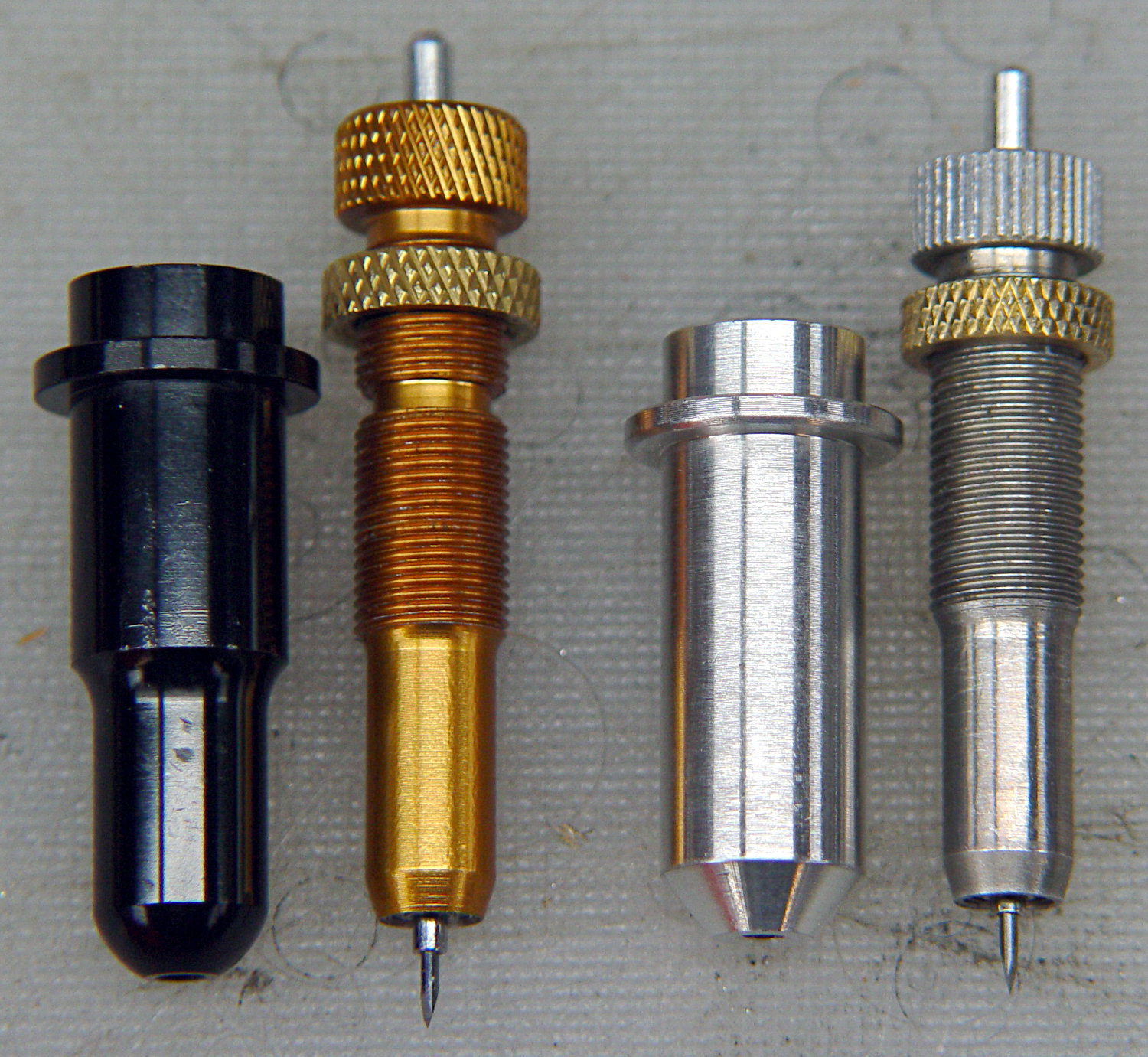
Having reasonable success using a 12 mm hole bored in a 3D printed mount for the nice drag knife holder on the left, I thought I’d try the same trick for the raw aluminum holder on the right side:
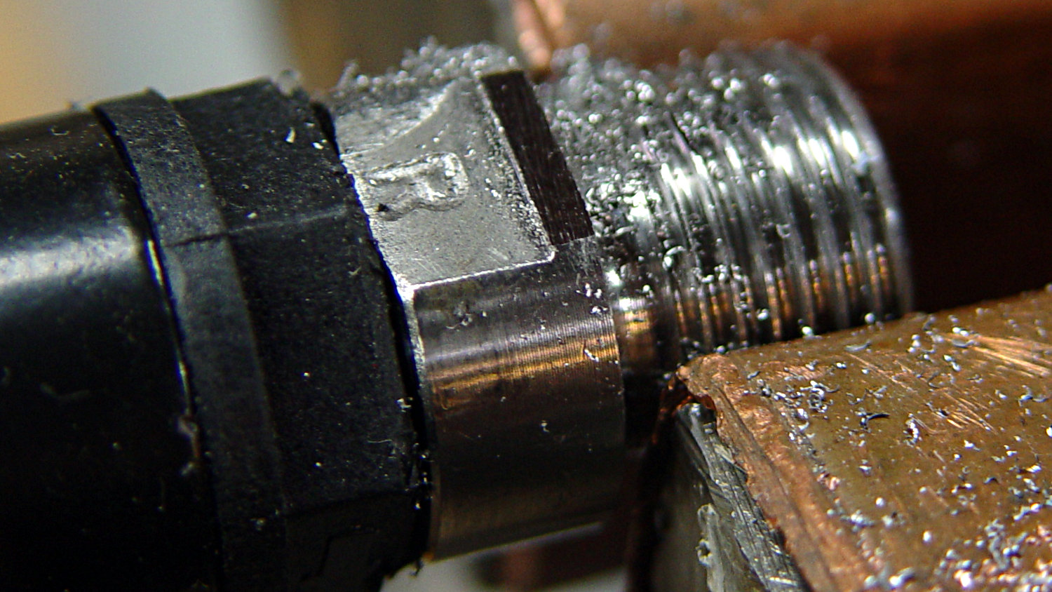
The 11.5 mm body is long enough to justify making a longer holder with more bearing surface:

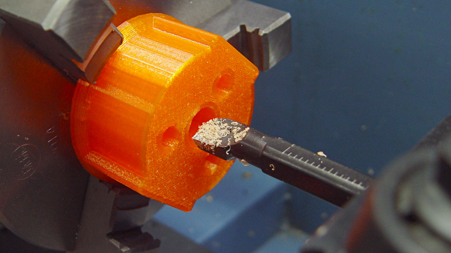
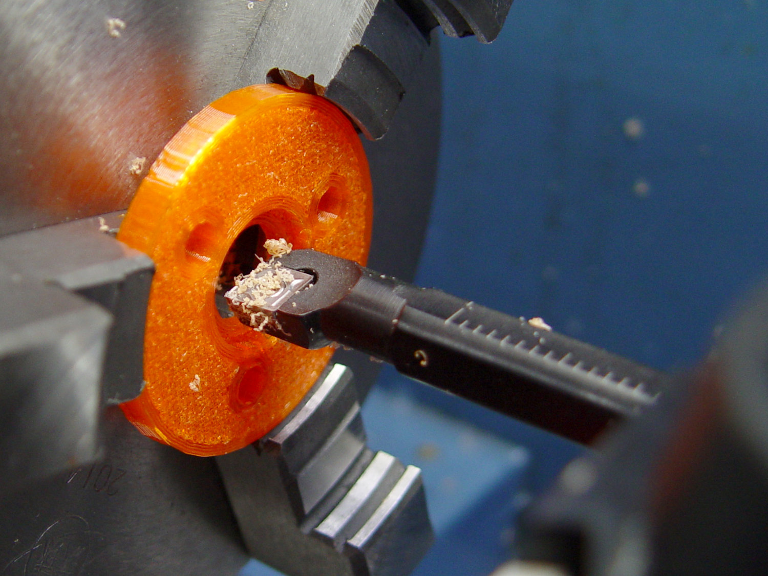
Slicing with four perimeter threads lays down enough reasonably solid plastic to bore the central hole to a nice sliding fit:
The top disk gets bored to a snug press fit around the flange and upper body:
Assemble with springs and it pretty much works:

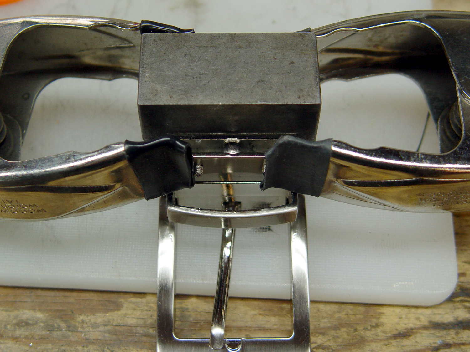
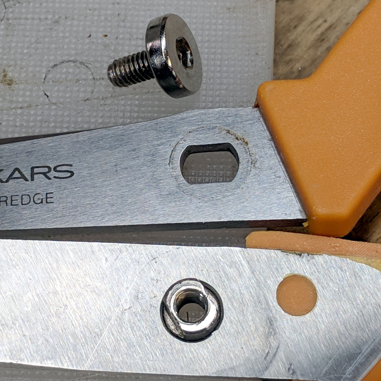
Unfortunately, it doesn’t work particularly well, because the two screws tightening the MPCNC’s DW660 tool holder (the black band) can apply enough force to deform the PETG mount and lock the drag knife body in the bore, while not being quite tight enough to prevent the mount from moving.
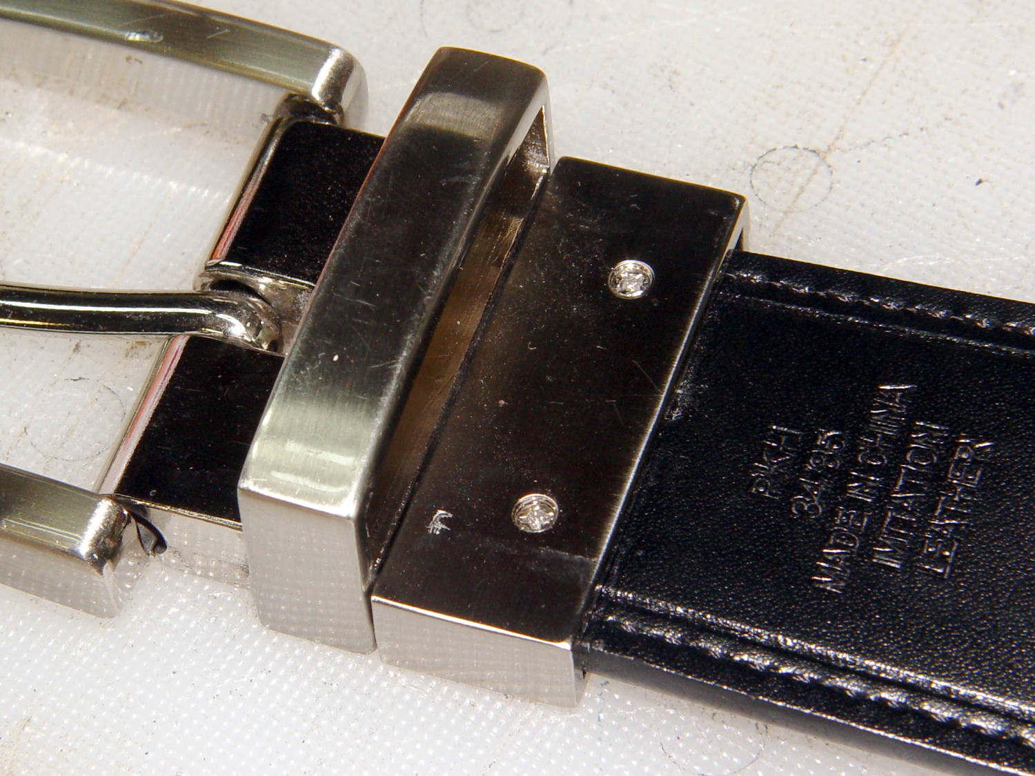
I think the holder for the black knife (on the left) worked better, because:
- The anodized surface is much smoother & slipperier
- The body is shorter, so less friction
In any event, I reached a sufficiently happy compromise for some heavy paper / light cardboard test shapes, but a PETG bearing won’t suffice for dependable drag knife cuttery.
Back to the laboratory …