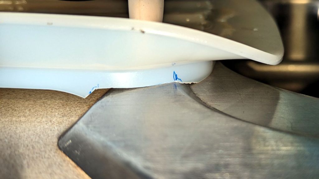
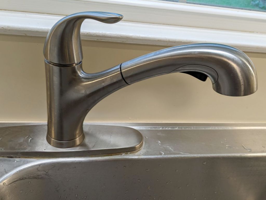
It seems all the drain boards under dish drainers are now intended for contemporary under-counter sinks without a rim, which is not the Old School drop-in sink we have in the kitchen. After considerable faffing about, I hacked a fix to make the drain board & drainer fit the sink:

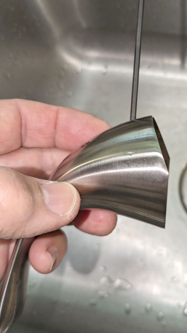
The crude notch not only lowers the front edge by a few millimeters, it also encourages the lip to stay over the sink, rather than sliding back over the counter and slobbering water everywhere.
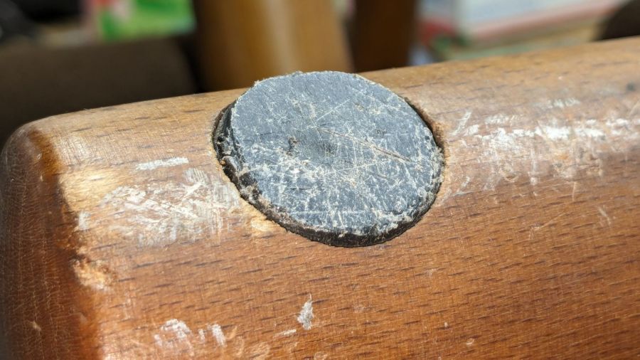
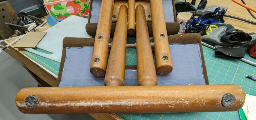
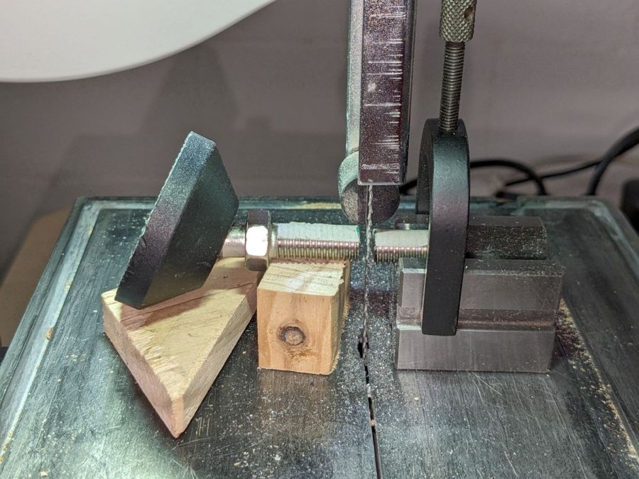
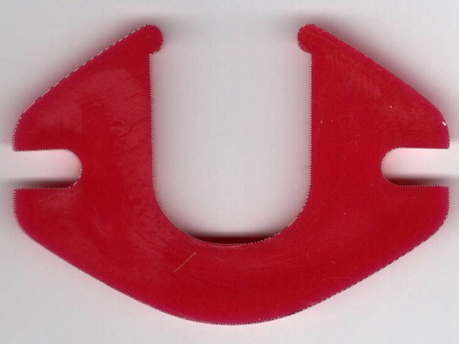
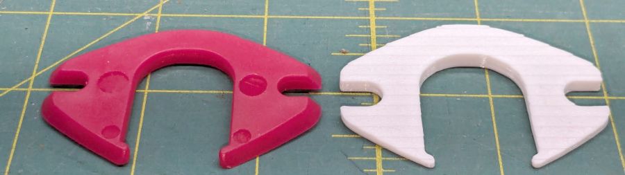
The drain board has stiffening ribs under the center section, cleverly arranged so they do not actually touch the counter. I measured the shape of the board near the ribs:
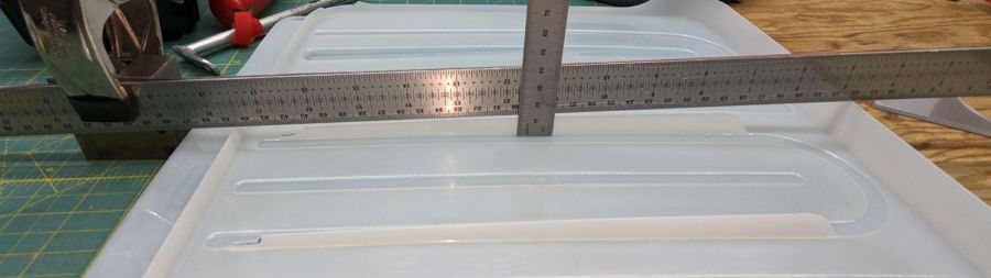
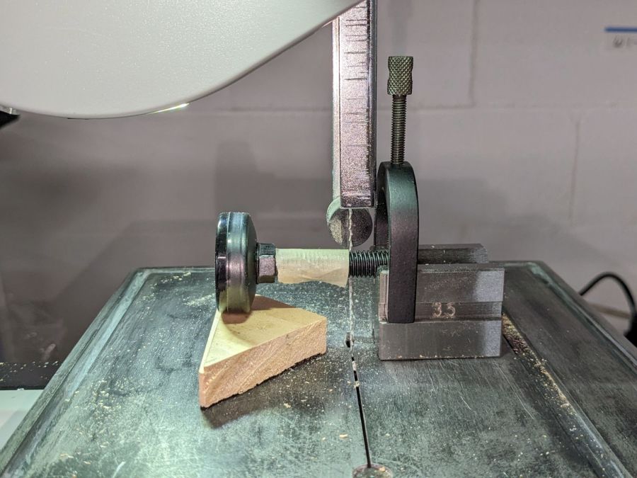
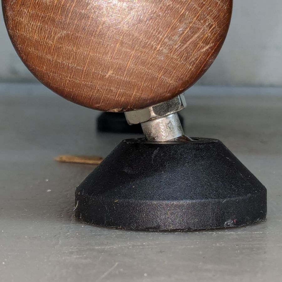
And then cut shapes to both support the board and rest on the counter:
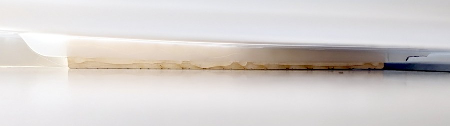
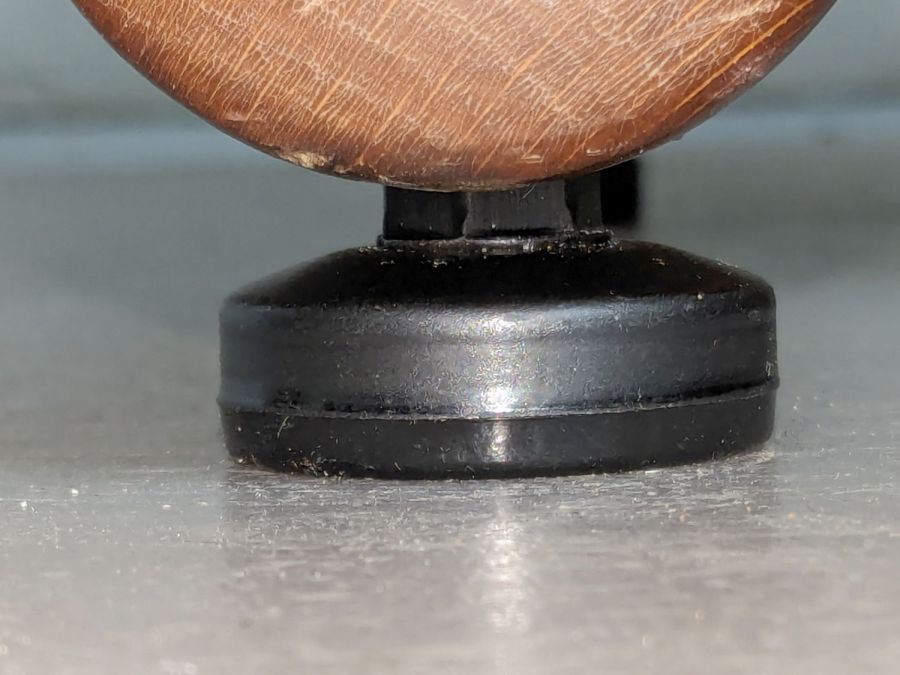
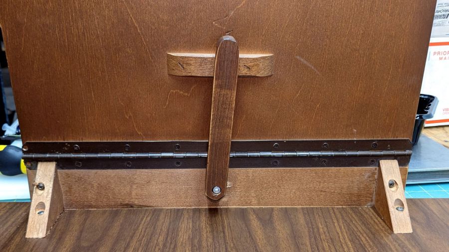
The board has a swale in the middle, directly over those ribs, requiring more tilt for proper drainage:
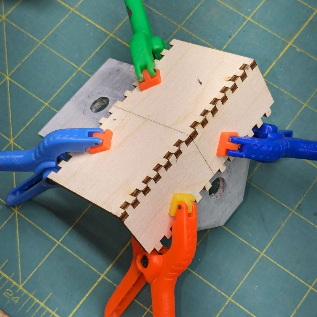
Getting all of that flying in formation required several iterations and we’re still not entirely satisfied, but at least the water flows into the sink and does not puddle in the drain board or on the counter.
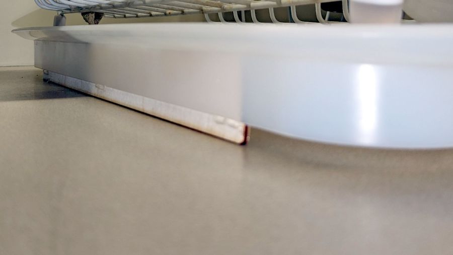
Stipulated: wood is the wrong material for the job, hot melt glue is breathtakingly ugly, and you want no part of this.
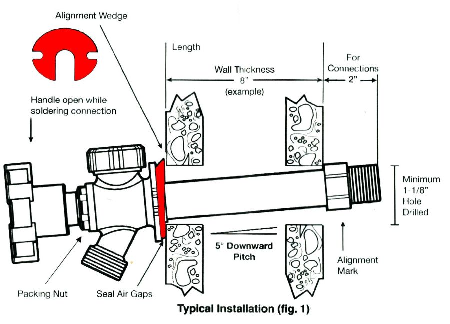
You can buy fancier drain boards, some with cute spouts leading into the sink, but the fine print suggests most expect to work with rimless under-counter sinks.


