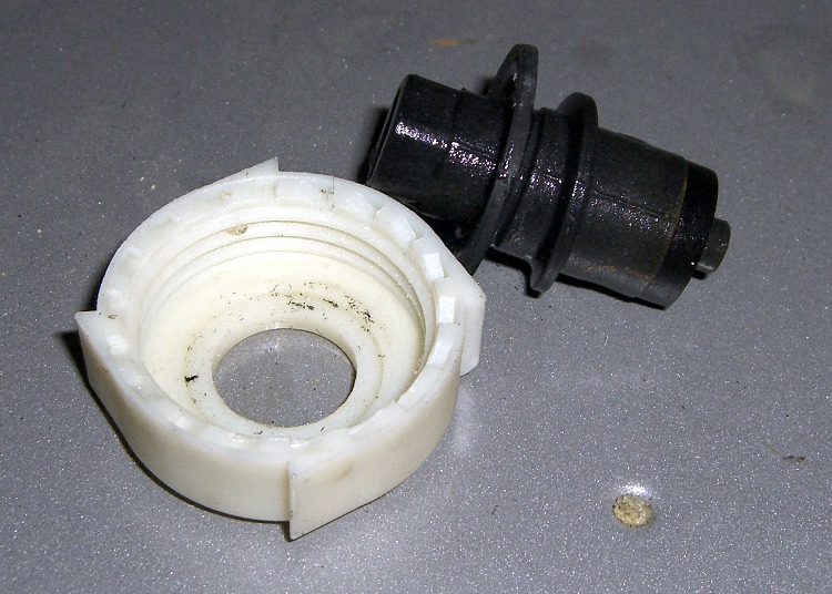
The Smell of Molten Projects in the Morning

Ed Nisley's Blog: Shop notes, electronics, firmware, machinery, 3D printing, laser cuttery, and curiosities. Contents: 100% human thinking, 0% AI slop.

Category: Home Ec

Things around the home & hearth

  • Sony DSC-H1 Shutter Button Repair: Putting It Together

    The story so far: Damage Assessment and Button Milling.

    Some key distances:

    • Bezel bottom 3.3 mm thick, excluding depression on bottom surface
    • Screw head sticks out of depression 0.9 mm

    Some deft work on the bezel installed in the camera, using the blunt end of a transfer punch, a pin vise, and a calculator reveals these protrusions:

    • 1.4 mm does not trigger anything
    • 2.1 mm triggers the half-pushed focus action
    • 2.4 mm reliably triggers the shutter

    So the new stem can stick out about 1.4 mm when the button is released and must not stick out more than 2.4 mm with the button fully depressed: a whopping 1 mm of travel!

    Eyeballing the shutter release on my DSC-H5, that seems to be about right. I think it has more travel between “released” and “half pressed” than those measurements indicate, but it’s close. And sloppy, too: the H5’s button has a lot of side-to-side wobble, indicating that the stem is not a close fit in the bezel hole.

    The screw head is 3 mm dia after being turned down and that’s about the right size for the nut that will adjust the travel distance, as it must fit into the recess in the bezel. The nut sets the protrusion when the shutter button is released: 1.4 mm.

    The distance from the shutter button’s bottom to the bezel sets the travel from “released” to “click”: 1 mm, more or less. They’re held apart by the spring, so that’s the default state.

    Circular Milling the Nut
    Circular Milling the Nut

    I re-centered the 3-jaw chuck under the spindle, put a 1-72 nut on the turned-down screw, and applied some gentle manual CNC to convert the nut from a hex to a disk. The trick is to approach the nut from the right side (the +X side) and go clockwise around it (climb milling), so that the cutting force tends to jam the nut against the screw head. Do it the other way and the nut will zip downward away from the cutter

    Surprisingly, I got that right the first time.

    Using a 2 mm end mill and figuring a 2.9 mm final diameter, the radius of the circle to move the end mill around the nut is:
    R = (2.9 + 2.0) / 2
    So the G-code for one pass looks like:

    #<R>=[[2.9+2.0]/2]
    G1 X#<R> F150
    G2 I[0-#<R>]
    
    Shutter Button Parts
    Shutter Button Parts

    Now, given the fragility of that setup, you don’t cut it all at once. You start from a diameter of maybe 4 mm and go down by 0.2 mm until you hit 3.0, then make a final pass at 2.9 mm. EMC2’s AXIS MDI mode makes this easy enough: type in the commands for a pass at 4.0 mm, then click on the previous command, change 4.0 to 3.8, and then just clickety-click.

    Spindle far too slow at 3000 RPM, feed at 150 mm/min seemed fine. Sissy cuts worked out OK.

    After the first few passes, my dim consciousness became aware of the fact that this is how I should have turned down the screw head…

    Button Assembly - Top
    Button Assembly – Top

    I cleaned up the bezel by putting it in an ultrasonic cleaner to shake the crud off, put it on a warm firewall router overnight to dry it out, then slobbered some Plastruct solvent adhesive into the cracks and clamped it for another night. The bezel was slightly out-of-round from the damage, so I hand-trimmed the bent plastic using a “high speed cutter” (#193, basically an end mill) in a Dremel flexible shaft at about 1/3 max speed until the shutter button bottomed out smoothly within the inner recess. Not a bit of CNC to be seen: hand held all the way.

    Button Assembly - Bottom
    Button Assembly – Bottom

    Then loosen the nut a bit, poke the screw through the bezel, put the spring on, and screw the shutter button in place. Adjust the nut so the screw head is 1.4 – 1.5 mm from the bottom of the bezel with the nut resting in the recess.

    Button Assembly - Pressed
    Button Assembly – Pressed

    Twiddle the shutter button until the screw head protrudes 2.4 mm from the bezel with the button pressed down.

    That’s measured with the hole-depth tang of a caliper, sitting atop the screw head. I don’t believe there’s 0.1 mm accuracy in the measurements, but they’re close enough. I did file off a few mold flash bumps from the shutter button & bezel during this adventure.

    Mark the screw threads above the button, unscrew it, chop the screw off with a stout diagonal cutter (it’s brass and not very thick, it’s OK), file the end flat, clean up the threads.

    The trick seems to be that the button must rest just below the inner ring of the bezel, so that it bottoms out smoothly when pressed. If it’s above the ring, then one side will hang up. The ring depth thus seems to limit the maximum travel, although I can’t say whether this is the way it’s supposed to work or not.

    I iterated & filed until the screw was flush with the top of the button with it screwed down to the proper position. It helped to figure out that one turn of the shutter button on the screw changed the “pressed” protrusion by 1/72″ = 0.35 mm.

    Urge some low-strength Loctite under the nut and into the shutter button’s hole, reassemble everything, and you’re done.

    Urethane Adhesive on Body Socket
    Urethane Adhesive on Body Socket

    The fall bent the bezel tabs so they no longer latch firmly in the camera body. I put two dabs of urethane adhesive on the socket in the body. The adhesive expands (foams!) as it cures; I hope it will lock the bezel in place while still allowing it to be removed if needed.

    I dabbed off most of the adhesive you see in the picture before installing the bezel; it’s not as awful as it looks!

    The final result has slightly less travel than the (undamaged, original) shutter button in my DSC-H5, but it works perfectly: half-press to focus, full press to trigger the shutter.

    Repaired Shutter Button
    Repaired Shutter Button
  • Sony DSC-H1 Shutter Button Repair: Damage Assessment

    Camera Body Damage
    Camera Body Damage

    My brother-in-law Tee dropped his Sony DSC-H1 camera, which landed atop its shutter button on the pavement.

    Bad news…

    • the shutter button broke off
    • the bezel popped out
    • the teeny little snap ring that held the shutter button stem in the bezel vanished, because…
    • the stem broke and the end vanished, too

    Good news…

    • apart from some scuffs, the camera still works
    • he managed to find the shutter button
    • and the button bezel
    • and the spring!
    Shutter Button - Spring - Bezel
    Shutter Button – Spring – Bezel

    A bit of browsing reveals that many, many Sony DSC-Hx (where x is an integer from 1 through 9, inclusive) owners have the same problem, minus the inconvenience & embarrassment of first dropping the camera. Turns out that the shutter button stem breaks at that notch in normal use.

    It seems the stem snaps while you’re taking pix, whereupon the spring launches itself and the button cap into the nearest river / drain grate / weedy area, never to be seen again. Tee is exceedingly fortunate to have found all the major pieces!

    Shutter Button Stem - End View
    Shutter Button Stem – End View.

    Here’s the broken end of the stem, with the button cap out of focus in the background. The stem is 1.5 mm in diameter, so the snap ring was surrounding, what, 0.75 mm of plastic? In what alternate universe did this design decision make sense?

    I think the snap ring contributed to the problem by eroding the stem in the notch; that little white stub isn’t half of the stem diameter; it may have stretched under impact, but surely not all that much.

    Yes, you can buy a replacement button for about 30 bucks direct from Sony, but it seems the new stem is subject to the same failure after a short while. They’re standing by the original design, marginal though it may be.

    Now, obviously, this stem failed from abuse, no argument there. Everybody else had their stem fail without provocation, though, so it really isn’t adequate to the task at hand.

    Bezel Socket View
    Bezel Socket View

    Anyhow, there’s also some damage at the bezel socket on the camera body, but nothing major. The dented silver areas on either side of the switch membrane are ESD shields, so that any static discharge from your finger will (most likely) dissipate on the external frame of the camera, rather than burrow into its guts via the switch.

    The bezel twist-locks into the camera body, which means that you can remove the bezel if you can get a good grip on it. It turns clockwise to remove.

    Shutter Switch Closeup
    Shutter Switch Closeup

    Peering closer at the membrane switch, it looks as though the button stem did some damage on its way out, although Tee admits to using various pointy objects to trigger the shutter while figuring out what to do with the camera.

    More good news: the switch still works correctly, including the focus function with the button half-pressed, That means the switch membrane and contacts are in good shape.

    Bezel - Top View
    Bezel – Top View

    The bezel itself is pretty well graunched, with a nest of cracks underneath that damaged arc to the left of the pictures. I think it’s in good enough condition that I can remove the bent plastic, ooze some solvent adhesive into the damage, and compress it enough to make everything stick together.

    Bezel - Side View
    Bezel – Side View

    Obviously, this calls for some Quality Shop Time!

    The overall plan is to remove the remaining stem from the button, drill-and-tap the button head for a miniature brass screw (1-72, I think), reshape the screw head into a membrane-friendly plunger (about 3 mm diameter and flat), then put it all back together with a nut in place of the snap ring.

    I should be able to install the bezel (without the button), then insert some drill rod through the hole to figure out how far the screw must protrude to trigger the focus & shutter switches. Perhaps a pin vise will grip the drill rod and bottom out on the bezel’s central ring, so I can do a trial-and-error fitting?

    Then I can adjust the screw to that overall length below the bezel with the button pressed, whack off anything that sticks out above the button, adjust the nut to limit the button’s outward travel, slobber Loctite over everything, and put it all together for the last time.

    That’s the plan, anyway. As the Yiddish proverb has it, “If you wish to hear G*d laugh, tell him your plans.”

    Some useful dimensions…

    Button Dimensions
    Button Dimensions

    The rest of the story…

    Rebuilding the button

    Putting it all back together again

  • Tour Easy Zzipper Fairing Wrappers: “Bubble Wrap”

    Tour Easy Zzipper Fairing Wrappers
    Tour Easy Zzipper Fairing Wrappers

    We spent four days biking along the Pine Creek Valley rail trail with a Rails-to-Trails Conservancy group ride on our Tour Easy recumbent bikes. Because a crushed-stone path creates a lot of noise that the fairings direct right into our ears and because we weren’t going very fast, we left the fairings at home. As a result, the bikes were wonderfully quiet.

    Some years ago, Mary sewed up “bubble wraps” to store our fairings on those rare occasions when they’re not on the bikes. She had some red flannel left over from another project and a hank of cheery Christmas-themed edging, so they turned out to be rather conspicuous.

    The trick is to get the size right when the fairing is rolled up. With the fairing in its natural bubble shape, the wrap is rather limp, so you need pockets on both ends to hold the wrap in place. The toes are, she admits, an affectation, but didn’t take much figuring to get right. The width is just slightly more than the fairing’s flat width; you find that by rolling it up and measuring the roll.

    She actually made a paper template first to sort out all the curves, then transferred that to the flannel for final cutting.

    Tuck in the fairing’s head & toes, roll it up toes first, tie the (attached) strap in a neat bow, and it’s done!

    We have three fairings and they roll up together, each in its own wrap, into one tidy, albeit rather heavy, package.

  • Bicycle Water Bottle Cap: Relaxed

    Water bottle cap
    Water bottle cap

    Being cyclists, we were doing the resuable-water-bottle thing long before it became trendy, but now that we use hydration packs, we just tote bottles along when we’re driving or on some other sort of outing. Eventually the bottles wear out / get lost and we page a new one in from the essentially infinite stash in the bottle cupboard.

    This one had a cap that simply couldn’t be pried open with bare hands, no how, no way. I eventually got it open by main force and the threat of high temperatures.

    Turns out there were two problems: the aperture in the pull-up ring is a wee bit small on the sealing nub and the ridge on the screw cap is about two wee bits large for the recess in the ring.

    The former succumbed to an O (letter Oh) drill, which I pulled & pushed through the hole by hand to enlarge the aperture from 0.320 to 0.332. It still seals reasonably well, although it’ll pee a thin stream under more pressure than you should apply to such a bottle, which means I put a slight scratch on the aperture.

    The latter required gently shaving the ridge with a box cutter (gasp). It’s still rather stiff, but entirely workable. That doesn’t affect the seal, because the ring’s skirt is a snug fit against the screw cap.

    Why not just throw the fool thing out? After all, it’s just a freebie water bottle…

    We run on the “Use it up, wear it out, fix it once, wear it out again, then put it on the shelf because maybe you can use the parts for something” principle.

    Now, that’s not the way things are done these days, but it works for us…

  • Pressure-washing the Gas Grill: Mind the Overspray

    The instructions for our Weber gas grill would have us lavish more care on it than we do on our car, which isn’t actually saying much. Nonetheless, once a year I gotta clean the crud out, whether it needs it or not, because not even I believe heat kills that stuff.

    Used to be, that was a thoroughly disgusting job of hand-scraping carbonized gunk and scrubbing gooey muck in cramped quarters. Having acquired a pressure washer, cleaning the grill is almost enough fun that I might do it more often. It even gets the mildew (or whatever that schmutz might be) off the wood handles & platforms, which I would have bet was impossible.

    Pressure washer side effects
    Pressure washer side effects

    However, if you’re even a teensy bit fussier than we are about the looks of your castle, you might want to not lay the grates & “flavorizer bars” on the driveway to blast ’em clean. Turns out that the overspray strips the grunge right out of the top layer of asphalt, leaving a white trail behind.

    Looks a lot like those Nasca peteroglyphs, doesn’t it?

    The pressure washer does a great job on the white resin plastic chairs, too, which go from really grubby to chalk-white in one pass.

    Can’t imagine how I got along without it…

    Memo to Self: Next time, use the sawhorses.

  • Batteries.com Alkaline AA Cells: Early Failures Thereof

    Swollen vs normal alkaline AA cells
    Swollen vs normal alkaline AA cells

    I’ve bought plenty of batteries from batteries.com over the years, but the alkaline AA cells I picked up last year have been a real disappointment: some had very short service lives. It took quite a while to figure this out, as I mentioned there, and when I finally got around to checking the rest of the package, most of them were dead… in Spring 2009 with a 12-2012 date code.

    One characteristic of the weak / dead cells is that the negative terminal is swollen, even on the deaders direct from the package. This picture shows four cells removed from service: the front two are used with some remaining charge, the rear two are dead.

    When I checked the package, most of the dead-on-delivery cells had swollen bottoms, so I suspect they had a manufacturing problem with at least one batch of cells.

    A query to batteries.com asking about this got no reply. Perhaps they were busy dealing with the aftermath of their security breach?

    A 48-pack of alkaline cells from the late Circuit City, bought about the same time, seems just fine.

    Memo to self: check the bottom!

  • LED Flashlight Lens Protector

    Inova X1 lens protector
    Inova X1 lens protector

    Some years ago, a friend convinced me I needed an Inova X1 LED flashlight. He was right; I’ve carried one in my belt pack ever since and, in fact, added a couple of X5s to the household armory.

    Perforce, this is an old X1 with a coated glass lens to make the best of the LED. Newer X1s don’t have (or, likely) need the lens, as LED technology has made great strides in the last few years.

    I couldn’t bear the thought of that lens rattling around in my belt pack, chewed upon by the assortment of other crap in there. So I made a lens protector: a length of heatshrink tubing with a polypropylene window. You might want to do the same for your flashlight to keep from grinding up the optical surfaces on its shiny end.

    This tubing has an internal thermoplastic glue, but ordinary tubing would likely work as well. Position the tubing over the end of the flashlight with a few millimeters sticking out. Cut a circle from the clamshell case around some piece of consumer electronics, drop it on top of the lens, and shrink the tubing around the flashlight: watch it wrap right over the end and hold the circle in place. A dot or three of urethane glue may help for glue-less tubing.

    It’s transparent enough for most purposes, but when you really need more light or a tighter beam, pull it off. That’s aided by dabbing a trace of oil on the X1, which you can get directly from the (outside) of your nose. Yeah, gross, but it’s a renewable natural resource…