Ed Nisley's Blog: Shop notes, electronics, firmware, machinery, 3D printing, laser cuttery, and curiosities. Contents: 100% human thinking, 0% AI slop.
While setting up the small table I conjured from scrap, I discovered one of the folding legs no longer had a latch to keep it from folding. Whether it never had one or the latch got lost along the way, there’s no time like the present:
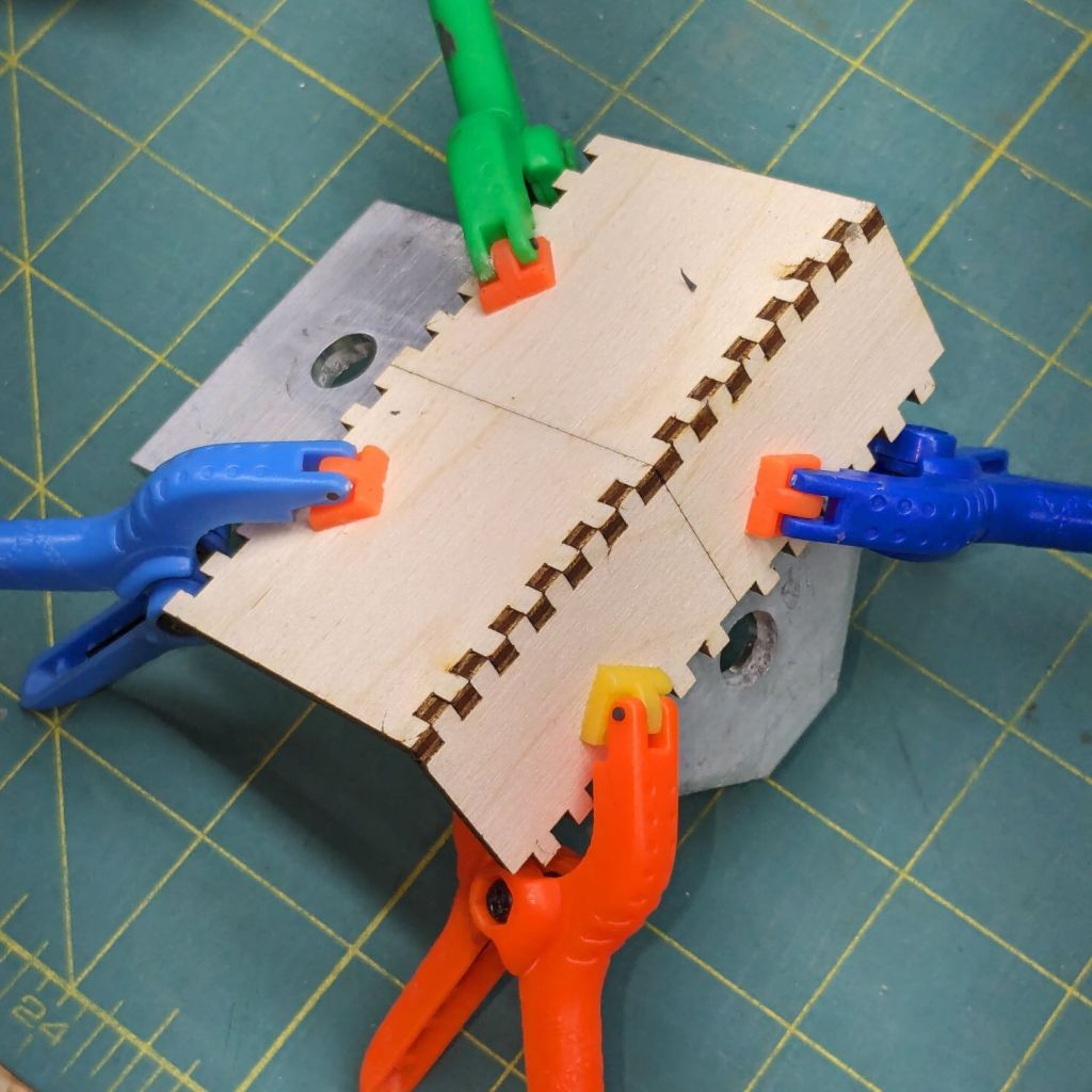
Table leg latch – installed
The bolt I put there in place of the joint rivet precludes a smaller latch along the lines of the simple steel loop on the other leg, so I figured I may as well go large and, with that much surface area, plywood will work just as well as steel for my simple needs.
When those set, I glued & clamped them together in situ, then wrapped the whole mess with what’s basically high-strength friction tape to encourage it to not come too far apart under the inevitable stress when the leg tries to fold with a pile of stuff on the table.
We’ll see how long this survives; if past experience is any guide, it’ll be a while.
The WordPress AI image generator has a shaky grasp of both human anatomy and the blog topic:
Woodwork design by Escher. What is that interesting tool? So many arms, all with nightmare fuel anatomy!
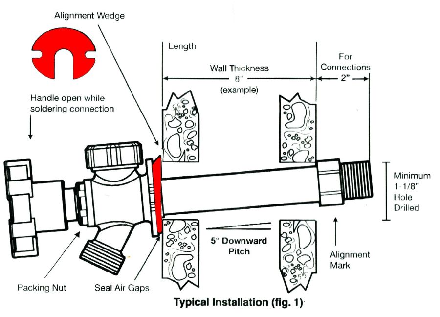
A pair of frost-free sillcock faucets arrived to replace the house’s leaky and un-repairable hose bibs. The faucet must be mounted at a 5° angle to let the water drain out when it’s closed:
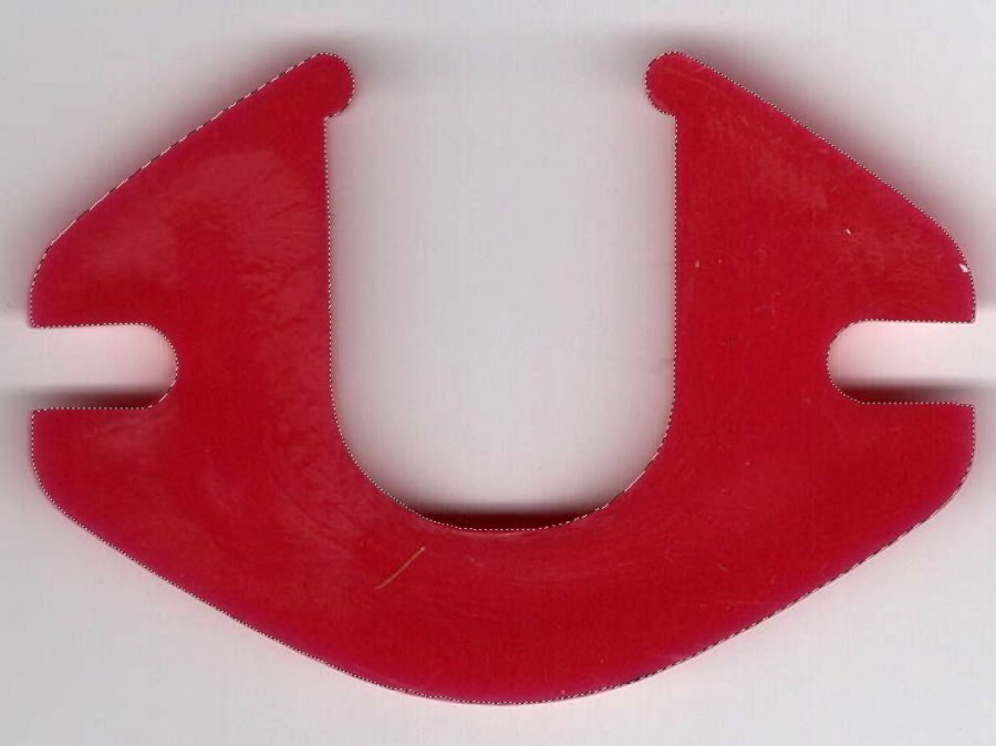
Sillcock faucet alignment wedge – GIMP color selection
After a little manual cleanup in Quick Mask mode, apply a 1 mm inset to ensure it snaps around the pipe, convert the selection to a path, export it as an SVG image, and import it into OpenSCAD to cut the angle:
And comes off the printer looking just about like you’d expect:
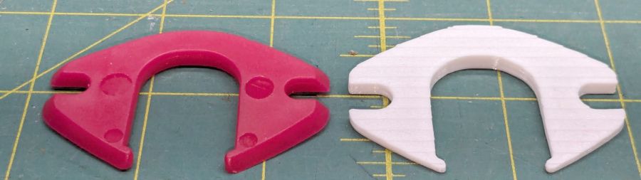
Sillcock faucet alignment wedge – OEM vs printed
The far side of both wedges are 5 mm tall, but you can see the difference four more degrees makes in the front.
It’s even more obvious from the edge:
Sillcock faucet alignment wedge – on pipe
The wood siding where these will fit is perfectly vertical, so getting the wedge angle right isn’t really optional.
I must drill the existing hole in the sill plate out to 1-1/8 inch to clear the pipe fittings, plus the wood around the screws holding the current bibs to the wall will surely need some buttressing, but all that’s in the nature of fine tuning.
FWIW, this was the first 3D print after the move and I’m happy to say the M2 had no any need of adjustments.
The WordPress AI image generator apparently ignored the post text and produced a stylin’ picture of an arched bathroom faucet over a rimless sink, which I shall leave to your imagination.
Long ago, I got Mary a cheap “desk calculator” with a vital function: it beeps cheerfully with each keypress. Nothing lasts forever and the aluminum dress panel around the keys has been gradually working its way loose.
So, we begin …
Gingerly remove the panel, un-bend and flatten it, lay it on the scanner, and cover with black paper:
C-Power calculator keyboard cover
Blow out the contrast, threshold the image, do a little touchup, and get a binary mask:
C-Power calculator keyboard cover – mask
Import into LightBurn, trace and discard the image, do some shape optimization, add 0.2 mm to the height & width of one key, propagate those dimensions to other keys (Make same width and Make same height FTW), cut a paper prototype to verify the fit, iterate until it drops neatly into place, cut an adhesive sheet, then peel & stick:
C-Power KK-800A keyboard – adhesive placed
The dress panel was held in place by what was once a quick-setting gooey glue that had long since fossilized. Although it gave up on the aluminum, it was not going to come off the calculator body without more struggle than seemed warranted.
So I stuck the new glue atop the old glue and hoped for the best. You can see traces of the old glue bead through the sheet:
C-Power KK-800A keyboard – adhesive ready
Lay the dress panel in place, burnish between the rows & columns, and it looks about as good as it ever did:
C-Power KK-800A keyboard – restored
If the adhesive sheet also gives up on the aluminum, I’ll try some fancy 3M 300LSE adhesive.
The WordPress AI image generator heard I like keys, so it spat out some keys for my keyboards:
The Sears sewing table (Model 853-9635, not that you have one) wrapped around Mary’s Kenmore machine has extension surfaces on both ends:
Sears Sewing Machine Table – overview
The foot panel is secured by a simple wood latch that fell off the left side:
Sears Sewing Machine Table – stripped hole
Having some recent experience with this sort of thing, but not wanting to work under there, I waited for a pause in the sewing, then tried to remove just the hinged piece under the top surface. It turns out the joint is glued-and-screwed, so removing the two obvious screws didn’t do anything.
Dismounting the top surface at its other hinge and hauling the whole assembly to the Basement Shop showed this wasn’t the first time the latch had pulled its pivot screw out of the wood:
Sears Sewing Machine Table – stripped hole detail
The reason the screw pulled out of the top hole / slot is obvious when seen from the edge:
Sears Sewing Machine Table – screw obstruction
That’s one of the screws holding the piano hinge in place, but AFAICT the original latch screw also went right across that hole with maybe three threads engaging the wood.
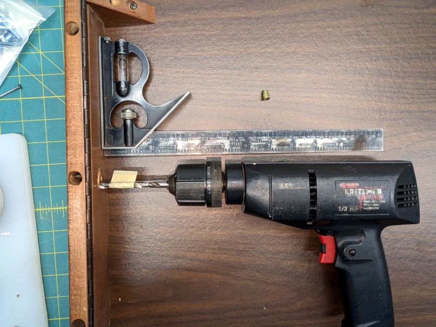
Moving the pivot half an inch to one side won’t make any difference, so I figured I could sink a threaded insert into the wood. I’d rather use the drill press, but sometimes you gotta do what you gotta do:
Sears Sewing Machine Table – insert drilling
The combination square gets the drill eyeballometrically perpendicular to the end piece and the drill lies flat on the (underside) of the table surface. Seeing the bit line up with where the hole had to be was confirmation this would be successful; all I had to do was proceed slow-n-steady with the brad-point bit and stop when the tape hit the wood.
The insert screwed in as expected, without any collisions:
Sears Sewing Machine Table – insert installed
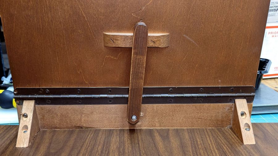
I drilled the wood latch to clear an M5 screw on the drill press, dabbed the screw with threadlocker, and reassembled everything on the bench for curing:
Sears Sewing Machine Table – latch installed
The extension surface on the right side of the table has an identical latch that hasn’t failed yet, but we agreed a preemptive repair is uncalled for.
The WordPress AI image generator is delivering much less jank, even if the result has little to do with the actual post:
Sears Sewing Table – WP AI image
Don’t think too much about the shadows, nor the lack of a treadle for what looks a lot like an early Singer Featherweight machine.
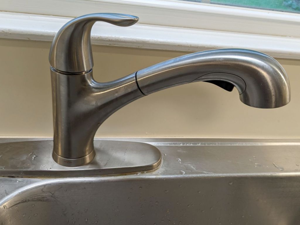
A “FastMount” push-and-turn nut secures the central pillar to the deck, although it had worked loose since it was installed some years ago. After retightening the nut, however, the faucet spout and handle remained loose, which I eventually figured out was due to the central pillar having worked loose from the plastic body inside the spout.
The solution involved releasing the FastMount nut, pulling the whole affair out of the deck, and tightening the threaded pillar into the body. After a few false starts, I applied a pair of grippy leather gloves and a firm grasp to twist the pillar another quarter turn into the body, after which it installed properly:
HD Glacier Bay kitchen faucet – realigned
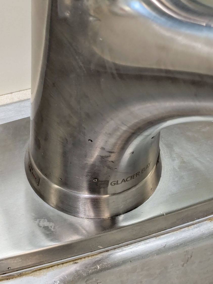
The mark on the far left shows how much I twisted the pillar:
HD Glacier Bay kitchen faucet – misaligned front mark
If I don’t tell anybody, they’ll never notice.
I fear this will not be permanent, in which case I must disconnect all the plumbing, take the faucet into the Basement Shop, and have my way with it. Most likely this will involve thread locking compound applied to parts that aren’t visible without a complete disassembly.
For the record, the setscrew securing the faucet handle to the valve fits a 2.5 mm hex wrench, aligned just about parallel to the handle rather than perpendicular to the rear surface:
HD Glacier Bay kitchen faucet – handle setscrew alignment
In comparison to the never-sufficiently-to-be-damned American Standard faucet in our previous kitchen, the spout does not depend on rotating O-ring seals, because the valve sends water to the integral sprayer through a flexible hose. Although the spout does have an O-ring at the bottom, it serves to keep casual splashes out, rather than pressurized water in.
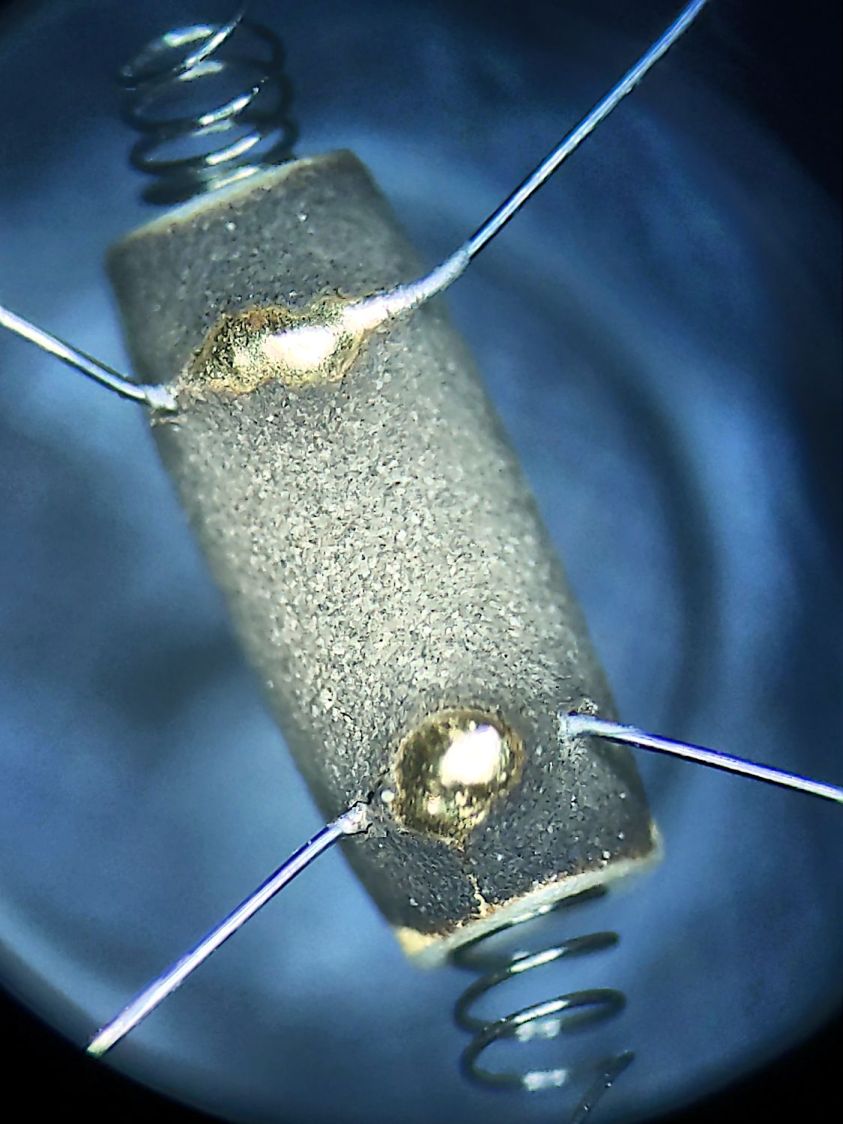
The granular surface does not get along well with the 5× digital zoom required to fill the phone’s sensor, but you get the general idea:
Figaro TGS880 – element detail
The heater measured 30 Ω on the dot and the sensor was an open circuit on the 100 MΩ range. Connecting the heater to a 5 V supply dropped the sensor resistance to 800 kΩ @ 50 %RH and a warm breath punched it to about 2 MΩ. That’s with an ohmmeter because I haven’t yet unpacked the Electronics Bench, but seems far above the spec of 20-70 kΩ in air.
So it’s still a sensor, even if it’s not within spec.
The WordPress AI-generated image for this post is … SFnal:
Figaro TGS-880 Gas Sensor – AI generated image
My pictures apparently aren’t up to contemporary blog standards …
The Samsung over-the-range microwave (ME18H704SFS, should you care) that Came With The House™ coughed up a C-11 error code resolving to “replace the gas / humidity sensor”. Replacement DE32-60013A sensors are readily available, although if you’re expecting a Genuine Samsung Part from Amazon, that is not the universe I live in.
You can remove the upper front bezel from the microwave to reveal the slotted front cover of the compartment containing the sensor, but you cannot replace the sensor without extracting the microwave from above the stove and removing its shell. The bottom of the microwave sits about 18 inches above the stove, so I put a 16 inch cubical moving box (of which we have a near-infinite supply) on the stove to reduce the risk of dropping the mumble thing while removing it.
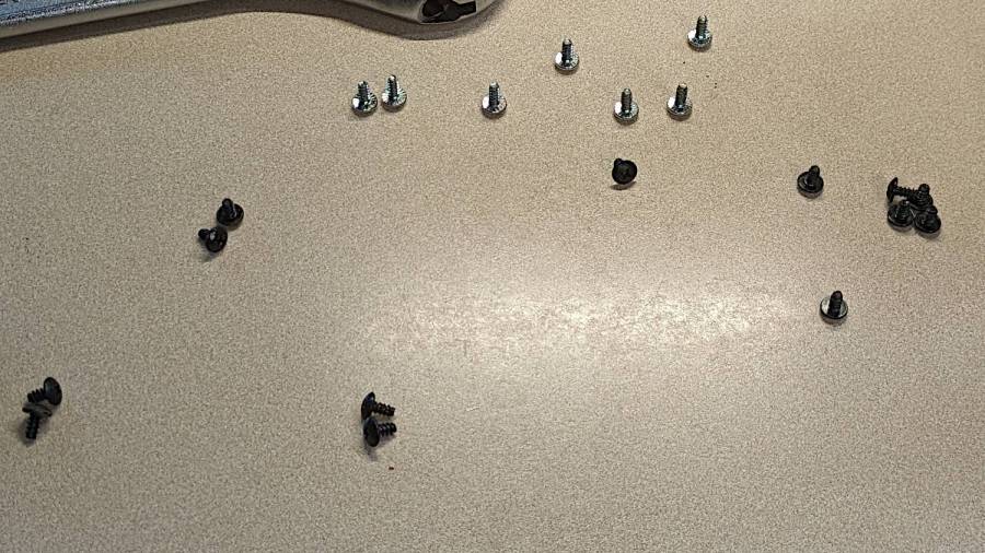
A total of 20 screws, here laid out in roughly geographic order, hold the shell to the inner frame:
Samsung microwave – cabinet screws
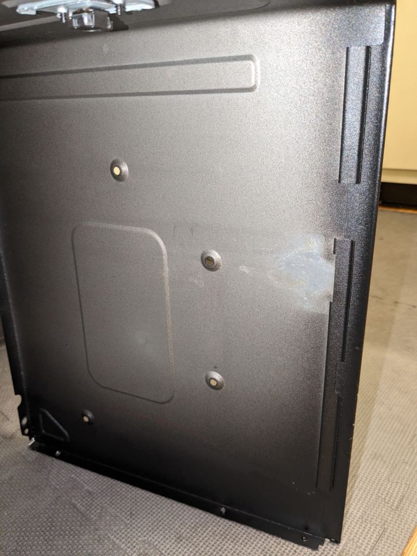
With all the screws out, slide the shell toward the rear by more than you might think to clear the latches along both sides. The latches along the front of the right side look like this:
Samsung microwave – shell side latches
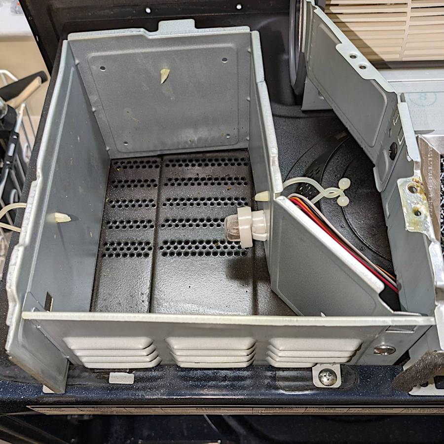
With the shell off, the sensor compartment on the top of the microwave enclosure is revealed:
Samsung microwave – TGS880 enclosure
Although you might think removing those two screws would grant access to the sensor compartment and let you replace the sensor (if you have very long fingers), that is not the case: the small tab toward the left side of the louvered front plate prevents you from sliding it and the plate is not hinged along its left side.
The sensor is held into the socket by a clip snapping into the arms that, in turn, hold the socket into the side wall:
Samsung microwave – TGS880 mount detail
A small screwdriver will assist in releasing the latches on the clip arms; squeezing them in the obvious way didn’t get the job done.
The old sensor then unplugs and the new one plugs in the obvious manner; it is not polarized and either orientation works.
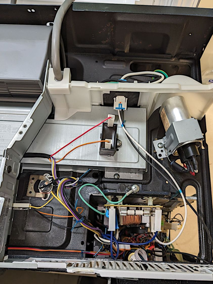
For completeness, the top of the electronics bay:
Samsung microwave – top interior
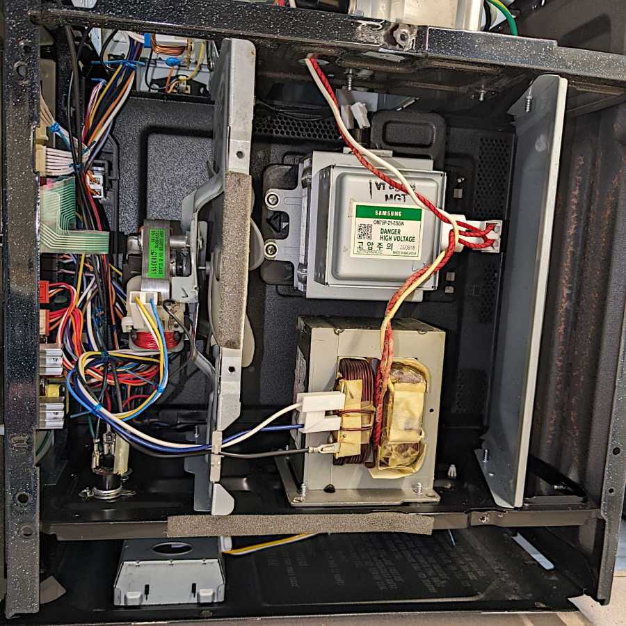
The magnetron and HV transformer live on the right side:
Samsung microwave – left interior
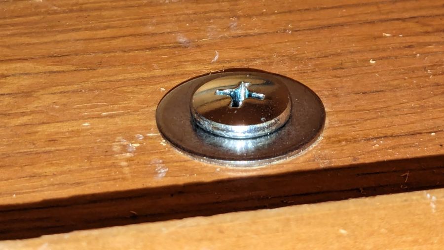
Then you reassemble in reverse order, heave the microwave atop the 16 inch cubical box, hoist it onto the rail along the back, and install the two loooong screws from the top while holding the front upward with one knee. I took the liberty of replacing the janky steel plates pretending to be washers with actual fender washers:
Samsung microwave – mounting screw
And now it works the way it should.
Of course, the microwave’s “beverage” mode assumes you’re drinking a piddly 8 ounces, rather than sipping from a manly 20 ounce mug:
Magnetic stirrer – vinyl surface
It heats 9 ounces of milk + cocoa just fine, but those 18 ounces of water for tea become just barely tepid.
WordPress has gone full-frontal AI and suggested I use this AI creation as the Featured Image:
The WordPress AI generated this evaluation of my writing:
The content provides a detailed guide on replacing the gas/humidity sensor in a Samsung over-the-range microwave. Consider adding subheadings to break down the process for easier reading. Additionally, including a brief introduction and a conclusion summarizing the key points would enhance the post. The technical details and images greatly support the instructions. Great job!


