The Smell of Molten Projects in the Morning

Ed Nisley's Blog: Shop notes, electronics, firmware, machinery, 3D printing, laser cuttery, and curiosities. Contents: 100% human thinking, 0% AI slop.

Category: Home Ec

Things around the home & hearth

  • Storm Door Brace: Now, With Inserts!

    The mid-1950s wood doors on our house have wood storm doors with interchangeable wood-framed glass and screen panels. Twice a year, the diligent homeowner will swap the panels to match the season; during the last 60+ years, the glass panels remain undropped.

    The back door has a diagonal tension brace to hold the door in shape; the door may be slightly distorted or the frame slightly out of square. In any event, the brace obstructs the panel, so the semiannual ritual includes loosening the brace and removing four screws. During the last 60+ years, the screw holes have required repair / filling several times; about five years ago, I plugged them with epoxy putty and drilled them to fit the screws.

    That repair having aged out, I was about to renew the epoxy when I realized that I now have brass inserts that would work even better, if I replaced the original wood screws with 10-32 machine screws.

    I cut the screws to the exact length using the brace and brass insert as a fixture:

    Storm door - screw cutting
    Storm door – screw cutting

    The vacuum cleaner nozzle to the lower right inhales the debris from the Dremel cutoff wheel that would otherwise fill the shop; I used up the last half of a wheel on four stainless steel screws.

    Because each end of the brace has two screws, I knew that I couldn’t just drill out the four holes, plant four inserts, and be done with the job: the first insert on each end could go pretty nearly anywhere, but the second insert must match the brace hole spacing. The only way I know how to do that is to epoxy the first two inserts in place and let them cure, drill the other two holes slightly oversize, mount those inserts on the brace, butter them with epoxy, put the brace in place, tighten the first two screws, snug the brace, and hope I didn’t epoxy the brace to the door or the screws to the inserts.

    Slips of waxed paper between the brace and the door prevented the first problem and oiling the screws prevented the second. It’s not the best-looking job I’ve ever done, but nobody will ever see the inserts behind the brace:

    Storm door - inserts
    Storm door – inserts

    Now, we’re ready for winter and I’m ready for spring!

    Most likely, the new owners (whoever and whenever they may be) will never use these inserts, as they’ll replace all the windows & doors, plus sand & refinish the hardwood floors, before moving in …

  • Kitchen Spatula Search

    A long long time ago, we bought a kitchen spatula that’s served us well ever since:

    Spatula Search - original
    Spatula Search – original

    To give you an idea of how old that poor thing is, the back of the handle bears a Japan stamp. I’ve re-set the rivets several times, the blade has rusted as badly as you think, and we recently, very reluctantly, decided it has passed its best-used-by date.

    The 3 x 4.5 inch blade is 19 mil = 0.45 mm plated carbon steel, stiff enough to remain flat and springy enough to bend a little, with a 9 inch = 230 mm steel handle ending in a plastic overmold.

    These days, it’s essential to the cutting, flipping, and serving of the morning’s omelet-like substance, made of eggs, bacon, veggies, green leafy things, plus this-and-that, in the cast-iron pan. Mary chops the disk into quarters with the reasonably sharp edge, maneuvers the reasonably bendy blade under each quarter, flips them over, tops with bacon & cheese, pauses for consolidation & melting, then pops them onto plates. Yum!

    Omelet in cast-iron pan
    Omelet in cast-iron pan

    So we set out to buy a replacement.

    Here’s what we’ve tried and rejected so far:

    Spatula Search - overview
    Spatula Search – overview

    I’ve used this one for many years to flip pancakes on a succession of non-stick griddles, a service at which it excels. The edge isn’t sharp enough to cut the green-and-leafy and the completely inflexible blade cannot be maneuvered under the omelet quarters:

    Spatula Search - heavy solid plastic
    Spatula Search – heavy solid plastic

    This one gets deployed for burgers and their ilk, also in the cast-iron pan. The blade, although sharp enough, is completely rigid:

    Spatula Search - heavy slotted metal
    Spatula Search – heavy slotted metal

    On the other paw, a slightly concave 7 mil = 0.18 mm spring steel blade is much too thin and, well, springy. Although very sharp, you cannot apply enough cutting force without suddenly bending the blade and, if the omelet quarter isn’t positioned exactly right, the blade will bend underneath it and dump breakfast on the stovetop. The alert reader will notice a missing weld between the blade and the bottom wire handle:

    Spatula Search - thin spring steel
    Spatula Search – thin spring steel

    This very thin plastic blade has similar problems with poor cut-ability and excessive flexibility:

    Spatula Search - thin springy plastic
    Spatula Search – thin springy plastic

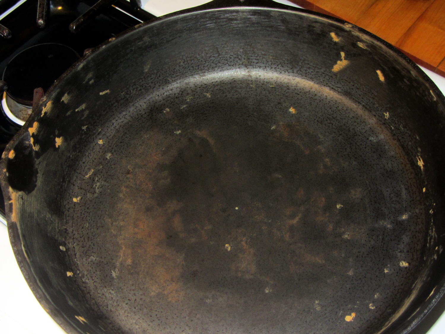
    This one looked really promising and worked almost perfectly. Regrettably, its nylon blade bears a 400 °F rating and the bottom of the omelet reaches nearly 450 °F. You can see what happens to the reasonably sharp edge as it scrapes across the pan:

    Spatula Search - heavy slotted nylon
    Spatula Search – heavy slotted nylon

    The omelet cooks at the temperature it cooks at, which part of the specifications is not subject to further discussion.

    So, we’re stumped. Having trawled the usual online and big-box stores, we’ve been unable to find a replacement. Simple steel blades aren’t available. Trendy silicone-bonded stainless steel blades combine the worst of all worlds: won’t cut and won’t flip. Pretty nearly anything you don’t see above seems obviously unsuitable for our simple needs: too big, too small, or too melty.

    We’ll consider all recommendations and suggestions! Thanks …

  • Hand Sprayer Hose Kink Prevention

    Mary’s new half-gallon sprayer arrived with a kink in the hose just below the handle, which is about what you’d expect from a non-reinforced plastic tube jammed into the smallest possible box containing both the sprayer and its wand. Fortunately, the Box o’ Springs had one that just fit the hose and jammed firmly into the handle:

    Sprayer hose with kink-resisting spring
    Sprayer hose with kink-resisting spring

    The kink slowly worked its way out after being surrounded by the spring and shouldn’t come back.

    That was easy…

  • American Standard Kitchen Faucet: Ceramic Valve

    It seems everybody must disassemble an American Standard kitchen faucet to replace the spout seal O-rings, as my description of How It’s Done has remained in the top five most popular posts since I wrote it up in 2009.

    About two years ago, I replaced the valve cartridge with a (presumably) Genuine Replacement; unlike the O-rings, the original valve lasted for nigh onto a decade. A few weeks ago, the replacement valve began squeaking and dribbling: nothing lasts any more. Another (presumably) Genuine Replacement, this time from Amazon, seems visually identical to the previous one and we’ll see how long it lasts.

    I always wondered what was inside those faucets and, after breaking off the latching tabs in the big housing to the upper right, now I know:

    American Standard Faucet - disassembled
    American Standard Faucet – disassembled

    You get a bunch of stuff for twelve bucks! The stainless steel valve actuator is off to the right, still grabbed in the bench vise.

    The valve action comes from those two intricate ceramic blocks with a watertight sliding fit:

    American Standard Faucet - ceramic valve parts
    American Standard Faucet – ceramic valve parts

    In fact, you (well, I) can wring the slabs together, just like a pair of gauge blocks. That kind of ultra-smooth surface must be useful for some other purpose, even though I can’t imagine what it might be…

  • Reticle Guide for Ruler Quilting

    I made the pencil guides to help Mary design ruler quilting patterns, but sometimes she must line up the ruler with a feature on an existing pattern. To that end, we now have a reticle guide:

    Ruler Adapters - pencil guide and reticle
    Ruler Adapters – pencil guide and reticle

    The general idea is that it’s easier to see the pattern on paper through the crosshair than through a small hole. You put the button over a feature, align the reticle, put the ruler against the button, replace it with pencil guide, and away you go.

    The solid model looks much more lively than you’d expect:

    Ruler Adapter - reticle - Slic3r preview
    Ruler Adapter – reticle – Slic3r preview

    Printing up a pair of each button produces the same surface finish as before; life is good!

    The OpenSCAD source code as a GitHub Gist:

    // Quilting Ruler Adapters
    // Ed Nisley KE4ZNU October 2016
    //- Extrusion parameters must match reality!
    ThreadThick = 0.25;
    ThreadWidth = 0.40;
    HoleWindage = 0.2;
    Protrusion = 0.1; // make holes end cleanly
    inch = 25.4;
    function IntegerMultiple(Size,Unit) = Unit * ceil(Size / Unit);
    //———-
    // Dimensions
    ID = 0;
    OD = 1;
    LENGTH = 2;
    Offset = 0.25 * inch;
    Template = [2.0,2*Offset,3.0];
    NumSides = 16*4;
    HoleSides = 8;
    //———————-
    // Useful routines
    module PolyCyl(Dia,Height,ForceSides=0) { // based on nophead's polyholes
    Sides = (ForceSides != 0) ? ForceSides : (ceil(Dia) + 2);
    FixDia = Dia / cos(180/Sides);
    cylinder(d=(FixDia + HoleWindage),h=Height,$fn=Sides);
    }
    //———-
    // Build them
    translate([-Template[OD],0,0])
    difference() {
    cylinder(d=Template[OD],h=Template[LENGTH],$fn=NumSides);
    translate([0,0,-Template[LENGTH]])
    PolyCyl(Template[ID],3*Template[LENGTH],HoleSides);
    translate([0,0,-Protrusion])
    cylinder(d1=2*Template[ID],d2=Template[ID],h=Template[LENGTH]/3 + Protrusion,$fn=HoleSides);
    translate([0,0,Template[LENGTH] + Protrusion])
    mirror([0,0,1])
    cylinder(d1=2*Template[ID],d2=Template[ID],h=Template[LENGTH]/3 + Protrusion,$fn=HoleSides);
    }
    translate([Template[OD],0,0])
    difference() {
    cylinder(d=Template[OD],h=Template[LENGTH],$fn=NumSides);
    for (a=[45,135])
    rotate(a)
    cube([0.70*Template[OD],0.15*Template[OD],3*Template[LENGTH]],center=true);
    }
  • Pencil Guides for Ruler Quilting

    Mary has been doing Ruler Quilting and wanted a pencil guide (similar to the machine’s ruler foot) to let her sketch layouts before committing stitches to fabric. The general idea is to offset the pencil by 1/4 inch from the edge of the ruler:

    Ruler Adapter - solid model
    Ruler Adapter – solid model

    That was easy.

    Print three to provide a bit of cooling time and let her pass ’em around at her next quilting bee:

    Ruler Adapter - Slic3r preview
    Ruler Adapter – Slic3r preview

    Her favorite doodling pencil shoves a 0.9 mm lead through a 2 mm ferrule, so ream the center hole with a #44 drill (86 mil = 2.1 mm) to suit:

    Ruler quilting pencil guides
    Ruler quilting pencil guides

    The outer perimeters have 64 facets, an unusually high number for my models, so they’re nice & smooth on the ruler. Even though I didn’t build them sequentially, they had zero perimeter zits and the OD came out 0.500 inch on the dot.

    The chamfers guide the pencil point into the hole and provide a bit of relief for the pencil’s snout.

    If I had a laser cutter, I could make special rulers for her, too …

    The OpenSCAD source code as a GitHub Gist:

    // Quilting Ruler Adapters
    // Ed Nisley KE4ZNU October 2016
    //- Extrusion parameters must match reality!
    ThreadThick = 0.25;
    ThreadWidth = 0.40;
    HoleWindage = 0.2;
    Protrusion = 0.1; // make holes end cleanly
    inch = 25.4;
    function IntegerMultiple(Size,Unit) = Unit * ceil(Size / Unit);
    //———-
    // Dimensions
    ID = 0;
    OD = 1;
    LENGTH = 2;
    Offset = 0.25 * inch;
    Template = [2.0,2*Offset,3.0];
    NumSides = 16*4;
    HoleSides = 8;
    //———————-
    // Useful routines
    module PolyCyl(Dia,Height,ForceSides=0) { // based on nophead's polyholes
    Sides = (ForceSides != 0) ? ForceSides : (ceil(Dia) + 2);
    FixDia = Dia / cos(180/Sides);
    cylinder(d=(FixDia + HoleWindage),h=Height,$fn=Sides);
    }
    //———-
    // Build it
    difference() {
    cylinder(d=Template[OD],h=Template[LENGTH],$fn=NumSides);
    translate([0,0,-Template[LENGTH]])
    PolyCyl(Template[ID],3*Template[LENGTH],HoleSides);
    translate([0,0,-Protrusion])
    cylinder(d1=2*Template[ID],d2=Template[ID],h=Template[LENGTH]/3 + Protrusion,$fn=HoleSides);
    translate([0,0,Template[LENGTH] + Protrusion])
    mirror([0,0,1])
    cylinder(d1=2*Template[ID],d2=Template[ID],h=Template[LENGTH]/3 + Protrusion,$fn=HoleSides);
    }
  • Miniblind Bottom Rail Caps

    A few days after installing the replacement cord caps, I bumped the bottom rail of the miniblind while opening the window and had one endcap disintegrate; apparently window hardware isn’t hardened against prolonged UV exposure. Who knew?

    Fortunately, I can fix that:

    Miniblind bottom rail caps
    Miniblind bottom rail caps

    Making the walls three threads wide provides enough room for a single solid infill thread:

    Miniblind Endcaps - Slic3r Preview
    Miniblind Endcaps – Slic3r Preview

    The exterior shape comes from a hull wrapped around six circles: four to define the corner radius and a pair that bump the center out by the calculated chord height. The interior shape comes from a pair of chord-radius polygonal circles (they only have three facets across the length of the inside wall) that fit the bottom rail almost perfectly.

    As always, natural PETG has a crystalline, slightly transparent, appearance:

    Miniblind bottom rail cap installed
    Miniblind bottom rail cap installed

    I should spring for some opaque white filament, but that way lies madness; I might start caring what these things look like.

    You can buy entire miniblinds for a few bucks a pop, but the last time we did that, they were different than the ones we had before. That wouldn’t matter if the standard miniblind mounting brackets fit our 1955 Anderson windows, but noooo they don’t: the custom adapters I machined for the first miniblind brackets, of course, didn’t fit the new miniblinds.

    Now I can just snap the replacement endcaps (and cord pulls) in place, declare victory, and move on.

    The OpenSCAD source code as a GitHub Gist:

    // Cap for miniblind cord and bottom rail endcaps
    // Ed Nisley KE4ZNU – September 2016
    Layout = "BaseEndCap"; // CordCap BaseEndCap
    //- Extrusion parameters – must match reality!
    ThreadThick = 0.25;
    ThreadWidth = 0.40;
    Protrusion = 0.1;
    HoleWindage = 0.2;
    //——
    // Dimensions
    OD1 = 0;
    OD2 = 1;
    LENGTH = 2;
    //———————-
    //- Build it
    if (Layout == "CordCap") {
    Cap = [9.0,16.0,25.0];
    Cord = [2.5,7.0,Cap[LENGTH] – 5];
    NumSides = 8;
    difference() {
    hull() { // overall shape
    translate([0,0,Cap[LENGTH] – Cap[OD1]/2])
    sphere(d=Cap[OD1],$fn=NumSides);
    translate([0,0,0.5*Cap[OD2]/2])
    sphere(d=Cap[OD2],$fn=2*NumSides); // round the bottom just a bit
    }
    translate([0,0,-Cap[LENGTH]/2]) // trim bottom
    cube([2*Cap[OD2],2*Cap[OD2],Cap[LENGTH]],center=true);
    translate([0,0,Cap[LENGTH] + 0.8*Cap[OD1]]) // trim top (arbitrarily)
    cube([2*Cap[OD1],2*Cap[OD1],2*Cap[OD1]],center=true);
    translate([0,0,-Protrusion])
    cylinder(d=Cord[OD1],h=(Cap[LENGTH] + 2*Protrusion),$fn=NumSides);
    translate([0,0,-Protrusion])
    cylinder(d1=Cord[OD2],d2=Cord[OD1],h=(Cord[LENGTH] + Protrusion),$fn=NumSides);
    }
    }
    if (Layout == "BaseEndCap") {
    Base = [25.2,9.0,12.2]; // base outside dimensions
    Edge = 8.0; // size of sqare ends
    CornerRadius = 0.75;
    Wall = 3; // wall thickness in threads
    ChordHeight = (Base[1] – Edge) / 2;
    ChordRadius = (pow(ChordHeight,2) + pow(Base[0],2)/4) / (2*ChordHeight);
    NumSides = 4*4;
    echo(str("Chord height: ",ChordHeight," radius: ",ChordRadius));
    difference() {
    linear_extrude(height=Base[2],convexity=2) {
    hull() {
    for (i=[-1,1], j=[-1,1])
    translate([i*(Base[0]/2 – CornerRadius + Wall*ThreadWidth),j*(Base[1]/2 – CornerRadius + Wall*ThreadWidth)])
    circle(r=CornerRadius,$fn=4*4,center=true);
    for (j=[-1,1])
    translate([0,j*(ChordHeight + Base[1]/2 – CornerRadius + Wall*ThreadWidth)])
    rotate(180/(2*4))
    circle(r=CornerRadius,$fn=2*4,center=true);
    }
    }
    translate([0,0,3*ThreadThick])
    linear_extrude(height=Base[2],convexity=2)
    intersection() {
    intersection_for (j=[-1,1])
    translate([0,j*(ChordHeight + Base[1]/2 – ChordRadius)])
    circle(r=ChordRadius,$fn=32*4,center=true);
    square([Base[0],2*Base[1]],center=true);
    }
    }
    }

    The original doodle with some dimensions that didn’t withstand careful measurements:

    Miniblind Endcap dimension doodle
    Miniblind Endcap dimension doodle