Ed Nisley's Blog: Shop notes, electronics, firmware, machinery, 3D printing, laser cuttery, and curiosities. Contents: 100% human thinking, 0% AI slop.
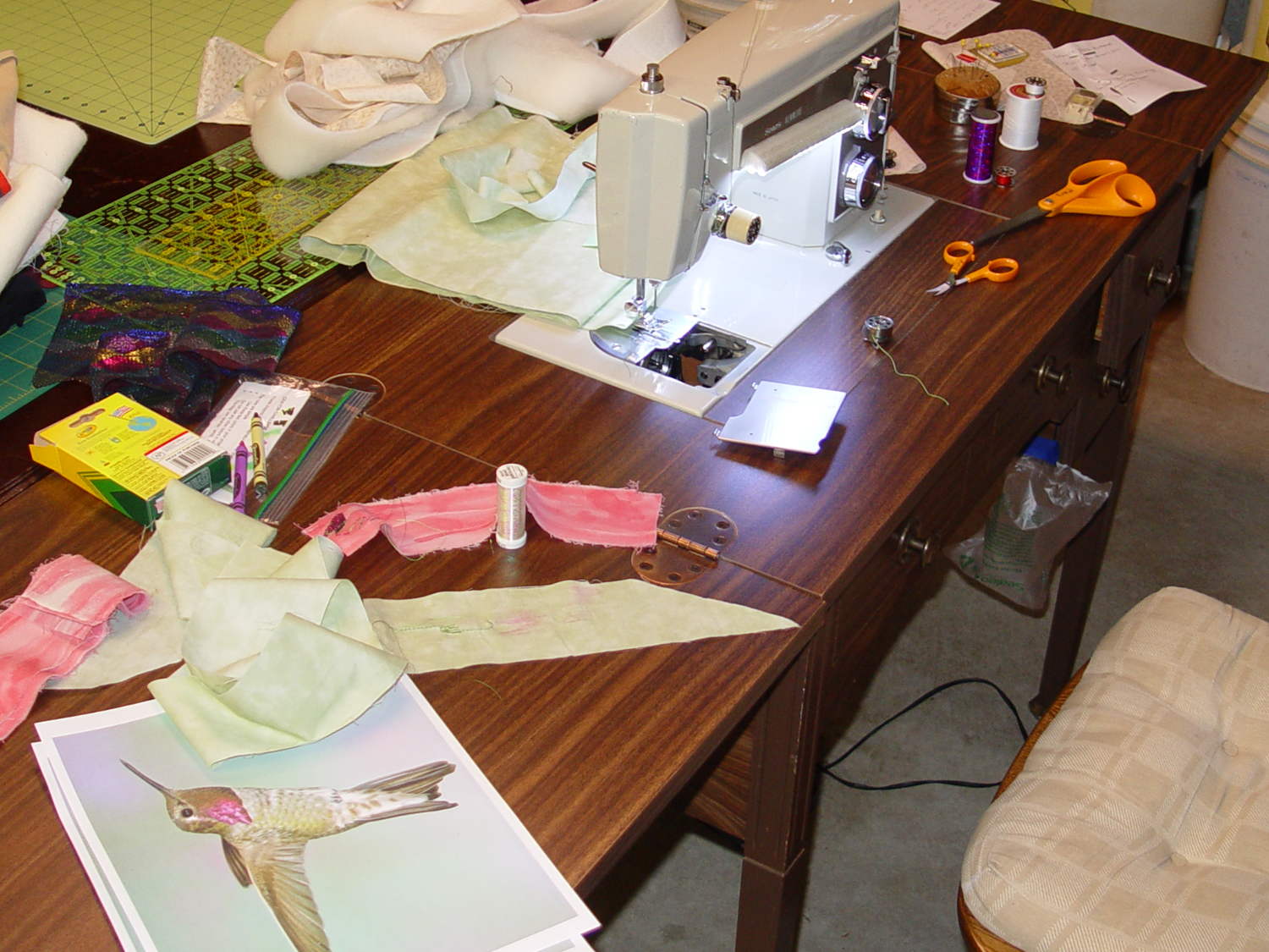
It has a number of shortcomings (notice the padding taped to the corner of the useless drawers), but the most pressing problem was that it didn’t quite line up with the table top in the Basement Sewing Room. After some pondering, we decided to shorten the legs and install leveling screws.
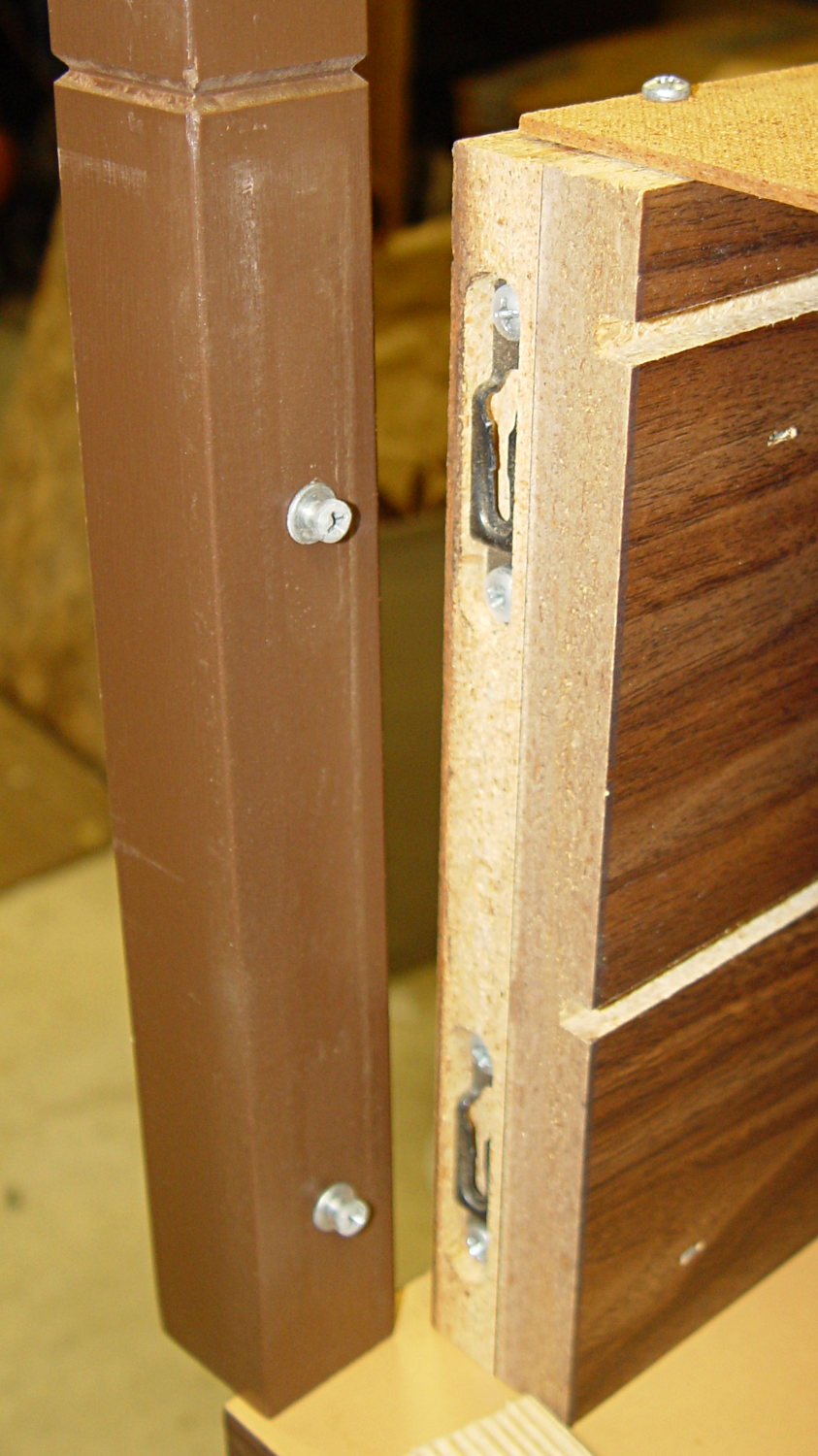
The first problem was figuring out how to dismantle the thing. It turns out the legs have completely hidden joint hardware:
Sears Sewing Table – leg joint hardware
They’re obviously intended as assemble-only fittings, but prying from the inside of the corners will put the tool marks where they can’t be seen:
Sears Sewing Table – leg removal
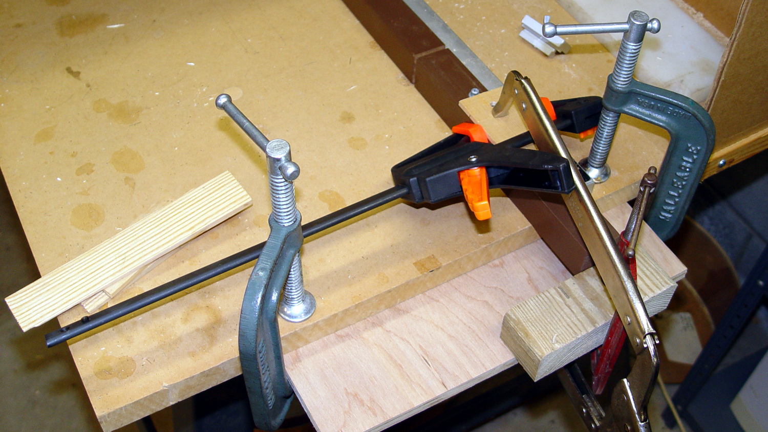
The legs taper below the fittings and require shims to prevent horrible saw accidents:
Sears Sewing Table – leg shortening
Another in my continuing series of Why You Can Never Have Too Many Clamps shows the square section of the leg aligned with the saw fence:
Sears Sewing Table – leg clamps
And when the cuttin’ were done, it turned out that the table had two different types of legs with (at least) two different lengths:
Sears Sewing Table – leg cutoffs
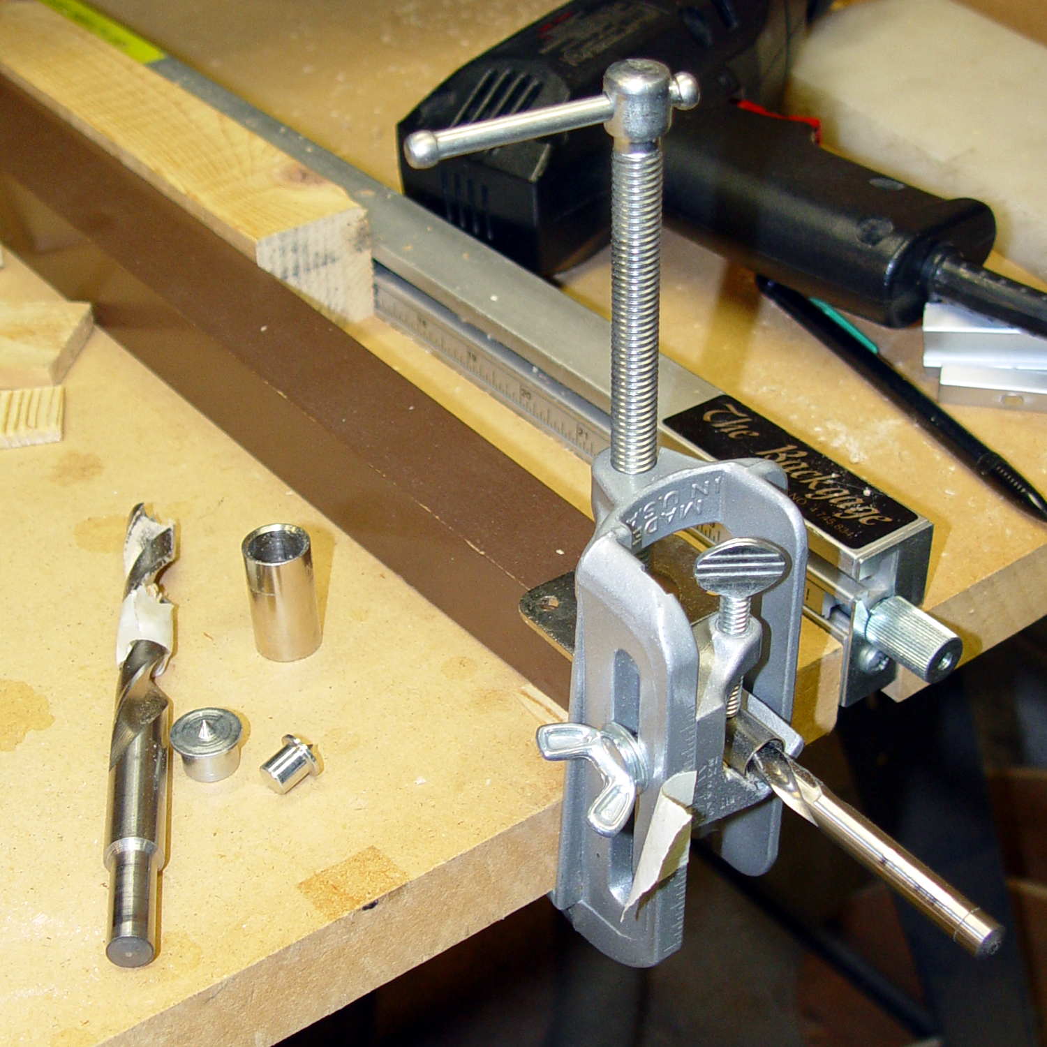
I have a bunch of 5/16 inch feet from some random industrial hardware, so I drilled a 5/16 inch hole into the legs, using a doweling jig and more shims:
Sears Sewing Table – leg drilling setup – overview
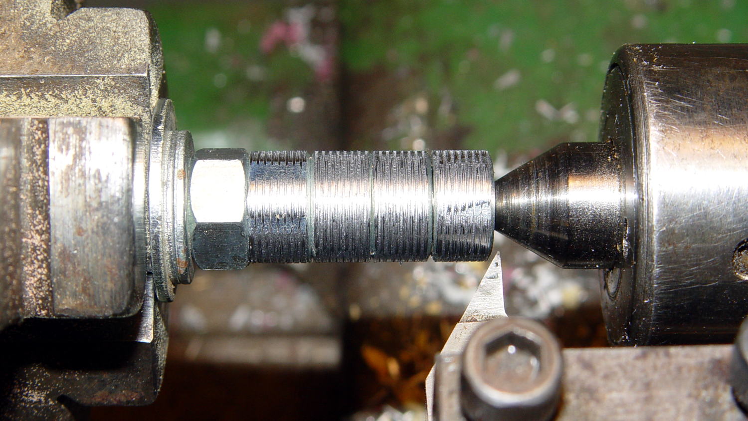
Normally, you’d bang a T-nut into each leg, but I thought those spikes would split the minimal wood remaining around the hole, so I turned the corners off a quartet of ordinary hex nuts and laid a coarse groove along their length:
Sears Sewing Table – preparing nut inserts
The modified nuts are 1/2 inch OD and you should drill that hole before the longer 5/16 inch clearance hole. I’ll eventually dab some epoxy in the holes, seat the nuts, and that’ll be a permanent installation with no risk of cracking the legs.
The snippet of tape on the doweling jig remembers the drill guide position, but the legs were sufficiently different that each one required different shims and some hand-tuning:
Sears Sewing Table – leg drilling setup – detail
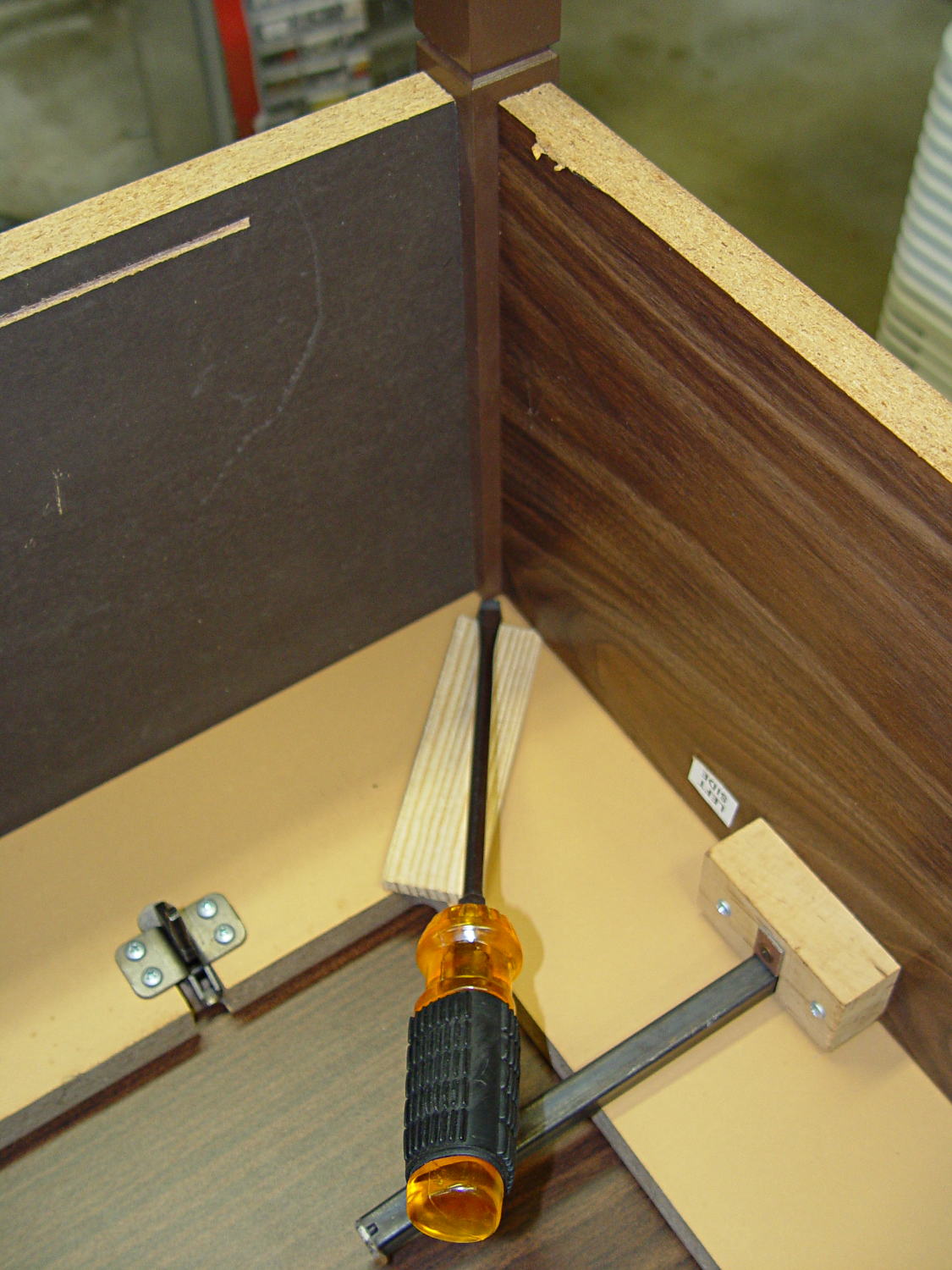
I dry-assembled the table in anticipation of more modifications. Basically, you wiggle-jiggle the leg studs into their latches, then whack the end of the leg with a rubber mallet to seat it against the underside of the tabletop.
Slicing another half inch off the legs seems like a Good Idea that should better match the upstairs table. Mary also wants to round off the drawers and remove a bit of the front panel, which will require dismantling the entire table, but that can wait for a pause in the quilting.
The burner in our oven failed in December 2006, probably because the charred remains of an insect produced a hotspot:
Burned Oven Tube Overview
That replacement burner came with its own igniter that failed after 8.5 years, with symptoms of slow oven ignition and the occasional smell of propane.
In normal operation, the igniter element glows yellow-hot for a minute or so before the valve opens, gas flows over the igniter, there’s a muffled whoomf, and the oven begins heating. The igniter remains powered as long as the oven is on, emitting a baleful yellow glare through the slots in the oven’s lower cover.
It consists of a ceramic base holding a stout resistance heater that apparently suffers from increasing resistance as it ages, reducing the current to the point where it won’t activate the gas valve.
I didn’t know that, either, but Google sees all, knows all, and tells most.
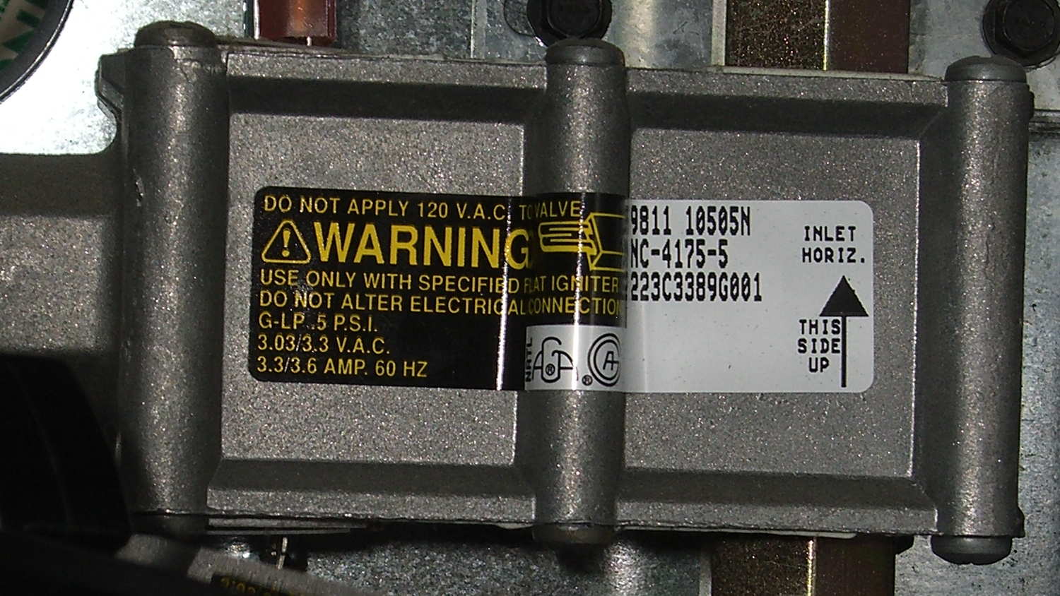
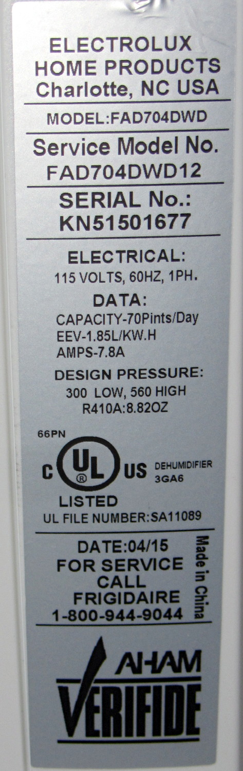
The gas valve label says it requires 3.3 to 3.6 A from the heater to turn on the gas:
Kenmore range oven gas valve – data plate
But the old heater was good for barely 2.6 A (there’s a bit of parallax in this view):
Kenmore range oven gas valve – weak igniter current
Igniters range from $18 to upwards of $60 on Amazon, so I picked the cheapest one, waited two days, installed it, and measured 3.5 A at First Light, down to a bit over 3.0 A at running temperature. That’s on the low side of the valve’s spec, but it seems happier with an extra half amp.
We’ll see how long this igniter lasts; maybe next time I’ll double my spend…
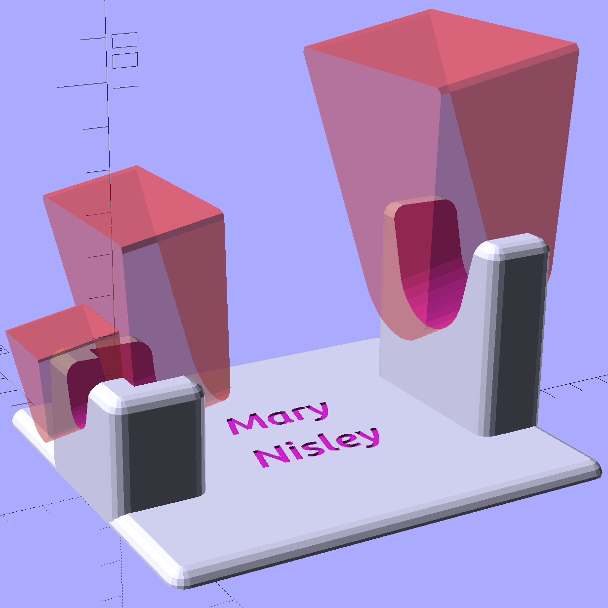
Mary flattens seam allowances and prepares appliqué pieces with a Clover MCI-900 Mini Iron. The stand resembles the wire gadgets that came with soldering irons, back in the day:
Clover MCI-900 Mini Iron – Clover holder
That stand may be suitable on a workbench, but it’s perilously unstable on an ironing board. After fiddling around for a while and becoming increasingly frustrated with it, she asked for a secure holder that wouldn’t fall over and perhaps had a heat shield around the hot end.
I ran off a quick prototype to verify my measurements and provide a basis for further discussion:
Clover MCI-900 Mini Iron – Level holder
I proposed screwing that holder to a rectangle of leftover countertop extending under the hot end, with a U-shaped heat shield extending upward to keep fingers and fabric away from the blade. She decided the countertop might be entirely too heavy and the heat shield might be too confining, so she suggested just angling the iron upward and adding a flat platform to stabilize it.
Her wish being my command:
Clover MCI-900 Mini Iron – Angled holder
I’m still not convinced that having the hot end up in the air is a Good Thing, but she thinks it’s worth trying as-is. A pair of 10-32 screw holes under each end will let it mount to a base board, should that becomes necessary.
I’ll stick a foam sheet under the platform so it doesn’t slide around. The cord normally dangles downward off the side of the ironing board or work table, so the iron won’t get up and walk away, but it might pull the whole affair toward the edge.
I should fill the letters with JB Weld epoxy darkened with laser printer toner (who knew?) to make them stand out. They’re more conspicuous in person than in the picture, so maybe it doesn’t matter.
The slots holding the iron have a semicircular bottom and straight-wall sides, created by extruding hulled 2D shapes, arranging them along the iron’s central axis, and tilting the “iron” at the appropriate angle:
Clover Mini Iron Holder – solid model showing iron
That’s a 10° tilt, chosen because it looked right. The model recomputes itself around the key dimensions, so we can raise / lower the iron, change the angle, and so forth and so on, as needed.
Assuming that a hot end sticking out in mid-air isn’t too awful, this one looks like a keeper.
The OpenSCAD source code:
// Clover MCI-900 Mini Iron holder
// Ed Nisley KE4ZNU - August 2015

Layout = "Holder";					// Iron Holder

//- Extrusion parameters - must match reality!

ThreadThick = 0.25;
ThreadWidth = 0.40;

function IntegerMultiple(Size,Unit) = Unit * ceil(Size / Unit);

Protrusion = 0.1;

HoleWindage = 0.2;

inch = 25.4;

Tap10_32 = 0.159 * inch;
Clear10_32 = 0.190 * inch;
Head10_32 = 0.373 * inch;
Head10_32Thick = 0.110 * inch;
Nut10_32Dia = 0.433 * inch;
Nut10_32Thick = 0.130 * inch;
Washer10_32OD = 0.381 * inch;
Washer10_32ID = 0.204 * inch;

//------
// Dimensions

CornerRadius = 4.0;

CenterHeight = 25;							// center at cord inlet on body

BodyLength = 110;							// cord inlet to body curve at front flange

Incline = 10;								// central angle slope

FrontOD = 29;
FrontBlock = [20,1.5*FrontOD + 2*CornerRadius,FrontOD/2 + CenterHeight + BodyLength*sin(Incline)];

CordOD = 10;
CordLen = 10;

RearOD = 22;
RearBlock = [15 + CordLen,1.5*RearOD + 2*CornerRadius,RearOD/2 + CenterHeight];

PlateWidth = 2*FrontBlock[1];

TextDepth = 3*ThreadThick;

ScrewOC = BodyLength - FrontBlock[0]/2;
ScrewDepth = CenterHeight - FrontOD/2 - 5;

echo(str("Screw OC: ",ScrewOC));

BuildSize = [200,250,200];					// largest possible thing

module PolyCyl(Dia,Height,ForceSides=0) {			// based on nophead's polyholes

  Sides = (ForceSides != 0) ? ForceSides : (ceil(Dia) + 2);

  FixDia = Dia / cos(180/Sides);

  cylinder(r=(FixDia + HoleWindage)/2,
           h=Height,
	   $fn=Sides);
}

// Trim bottom from child object

module TrimBottom(BlockSize=BuildSize,Slice=CornerRadius) {

	intersection() {
		translate([0,0,BlockSize[2]/2])
			cube(BlockSize,center=true);
		translate([0,0,-Slice])
			children();
	}
}

// Build a rounded block-like thing

module RoundBlock(Size=[20,25,30],Radius=CornerRadius,Center=false) {

	HS = Size/2 - [Radius,Radius,Radius];
	translate([0,0,Center ? 0 : (HS[2] + Radius)])
	hull() {
		for (i=[-1,1], j=[-1,1], k=[-1,1]) {
			translate([i*HS[0],j*HS[1],k*HS[2]])
				sphere(r=Radius,$fn=4*4);
		}
	}
}

// Create a channel to hold something
// This will eventually be subtracted from a block
// The offsets are specialized for this application...

module Channel(Dia,Length) {

	rotate([0,90,0])
		linear_extrude(height=Length)
			rotate(90)
				hull() {
					for (i=[-1,1])
						translate([i*Dia,2*Dia])
							circle(d=Dia/8);
					circle(d=Dia,$fn=8*4);
				}
}

// Iron-shaped series of channels to be removed from blocks

module IronCutout() {

	union() {
		translate([-2*CordLen,0,0])
			Channel(CordOD,2*CordLen + Protrusion);
		Channel(RearOD,RearBlock[0] + Protrusion);
		translate([BodyLength - FrontBlock[0]/2 - FrontBlock[0],0,0])
			Channel(FrontOD,2*FrontBlock[0]);

	}

}

//- Build it

if (Layout == "Iron")
	IronCutout();

if (Layout == "Holder")
	difference() {
		union() {
			translate([(BodyLength + CordLen)/2 - CordLen,0,0])
				TrimBottom()
					RoundBlock(Size=[(CordLen + BodyLength),PlateWidth,CornerRadius]);

			translate([(RearBlock[0]/2 - CordLen),0,0])
				TrimBottom()
					RoundBlock(Size=RearBlock);

			translate([BodyLength - FrontBlock[0]/2,0,0]) {
				TrimBottom()
					RoundBlock(Size=FrontBlock);
			}
		}

		translate([0,0,CenterHeight])
			rotate([0,-Incline,0])
				IronCutout();

		translate([0,0,-Protrusion])
			PolyCyl(Tap10_32,ScrewDepth + Protrusion,6);

		translate([ScrewOC,0,-Protrusion])
			PolyCyl(Tap10_32,ScrewDepth + Protrusion,6);

		translate([(RearBlock[0] - CordLen) + BodyLength/2 - FrontBlock[0],0,CornerRadius - TextDepth]) {

			translate([0,10,0])
				linear_extrude(height=TextDepth + Protrusion,convexity=1)		// rendering glitches for convexity > 1
					text("Mary",font="Ubuntu:style=Bold Italic",halign="center",valign="center");

			translate([0,-10,0])
				linear_extrude(height=TextDepth + Protrusion,convexity=1)		// rendering glitches for convexity > 1
				text("Nisley",font="Ubuntu:style=Bold Italic",halign="center",valign="center");
		}

	}
The M2 buzzed away for four hours on that puppy, with the first 2½ hours devoted to building the platform. That’s the downside of applying Hilbert Curve infill to two big flat surfaces, but the texture looks really good.
Plotters date back to the days before companies started using DRM to protect their monopoly positions, so refilling plotter pens requires little more than prying out the plug and squirting in more ink. Refilling the disposable liquid ink pens and the green ceramic pen suggested this would work.
I shaved down the side of a Genuine HP pen to find out why the plug didn’t pop out. It turns out the plug has a long and aggressively ribbed profile to ensure a gas-tight fit:
HP Plotter Pen – exposed plug
The easiest way to refill those is to drill an off-center 1/16 inch hole in the plug, then inject ink into the sponge with a syringe and blunt needle (and bulk ink!) from an inkjet cartridge refill kit. Angling the needle through the sponge close to the pen wall, then filling slowly, loads the sponge from the bottom up and expels the air along the way.
Inmac pens have a shallow plug, more of a flat cap, that pries out with zero drama:
Inmac Plotter Pen – removed plug
Dripping the ink atop the sponge seems to work well, although that sponge is definitely over-filled.
Inmac caps push back in place with zero drama.
The pens have fiber nibs with vent channels along their sides that allow air into the reservoir, so overfilling the sponge nets you a mess when you take the cap off the nib: those same channels allow excess ink to run from the reservoir around the nib, without (much to my surprise) wetting the fiber tip.
About 0.2 ml of ink fills the reservoir to saturation, 0.1 ml leaves it wet, and 0.05 ml seems to work well. The 1.0 ml syringes I’m using require about 0.05 ml to fill the (blunt!) needle shaft & hub, plus the syringe tip below the 0.0 ml index, so measuring the ink by drops might make practical sense.
The old physician’s trick of expelling that air by inverting the syringe and pressing the plunger until liquid squirts from the needle is so not happening…
I’ve had zero success refilling fossilized pens, probably because the OEM ink slowly evaporating from the nib clogs all the gaps between the fibers with pigment or coagulated solvent. Preemptively refilling good pens when they first show signs of running dry generally works well.
Given the number of New Old Stock pens I have that are still in their original wrappers, this is more of a “Does it work?” exercise than a necessity.
But, y’know, maybe becoming the last plotter pen refiller on the planet will be my ticket to fame & fortune! For sure, we’ve all seen over-hyped Internet startups with worse business plans and (the admittedly few) typewriter repair shops occupy a stable niche.
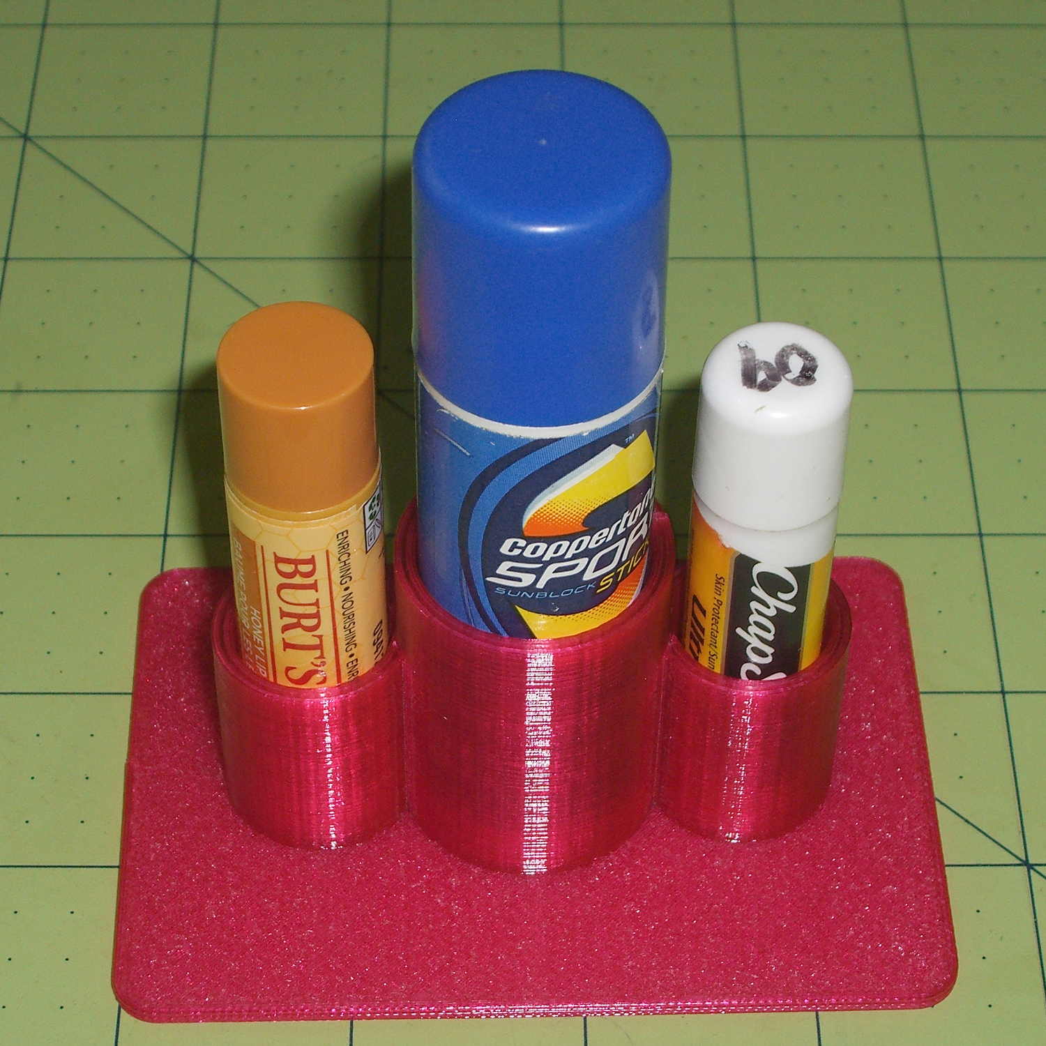
A bit of tinkering with the OpenSCAD code that produced the DeoxIT bottle holder delivered a place for the cylindrical objects we use just before cycling:
Lip Balm Holder
The tubes are 1.5 diameters tall, minus a skosh, so the cylinders stand neatly inside and don’t want to fall over. I added about 1 mm clearance and you could taper the cylinder openings for E-Z insertion, although we can eke out a miserable existence with this thing as-is.
It works exactly as you’d expect:
Lip Balm Holder – in action
That big stick in the middle is actually skin sunscreen, not lip balm; let’s not get all pedantic. The intent is to keep those cylinders from rolling off the shelf and falling into awkward locations, which this will do.
The OpenSCAD source code is strictly from empirical:
The step change in Week 22 shows when the replacement took over. After some poking around, Amazon Prime FTW.
The square-ish pulse starting in Week 26 marks a change from 55% RH to 60%RH and back again, to see how the front panel meter compares with the low end lab-grade hygrometer in the other side of the basement near the Hobo datalogger on the water inlet; they’re all off by a bit, but well within their expected tolerances. The 5% RH height of the step suggests a good match between their incremental calibrations.
It seems dehumidifiers last a few years, no matter which Brand Name you’ve decided to trust, so there’s not much point in developing a deep emotional attachment.
For the record, the old dehumidifier sported a GE label:
As it turns out, Electrolux bought Frigidaire a while ago, then absorbed GE’s appliances in 2014, so they’re all one big happy family now.
The various names notwithstanding, a recall notice suggests Gree Electric actually makes all the dehumidifiers badged with Brand Names you might think represent something significant.
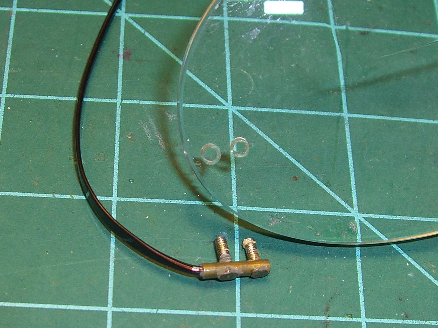
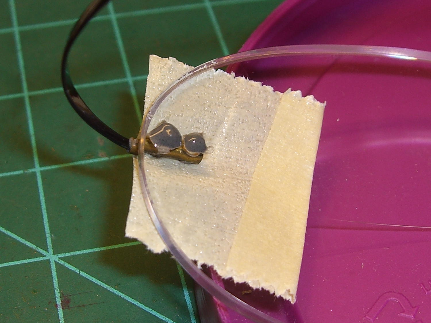
As failures go, that one’s survivable; slightly larger epoxy dots should do the trick:
Silhouette temple – re-repair
The other temple worked loose inside the brass tube and rotated freely, so I yanked it out, bashed the tip slightly flatter, and epoxied it back in place, along with overcoating the epoxy dots on the lens to forestall another failure.
This has obviously blown right by the point of absurdity, but …