The Smell of Molten Projects in the Morning

Ed Nisley's Blog: Shop notes, electronics, firmware, machinery, 3D printing, laser cuttery, and curiosities. Contents: 100% human thinking, 0% AI slop.

Category: Electronics Workbench

Electrical & Electronic gadgets

  • MPCNC: 12 V Supply vs. Stepper Current vs. Axis Speed

    The default MPCNC configuration wires the two stepper motors on each axis in series, doubling the total resistance and inductance of a single motor. The stock Automation Technology motor presents 2.8 Ω and 4.8 mH in each winding to the driver, for an L/R time constant of τ = 1.7 ms. Doubling both doesn’t change the ratio, but including the harness wiring resistance gives 1.6 ms = 9.6 mH / 6 Ω.

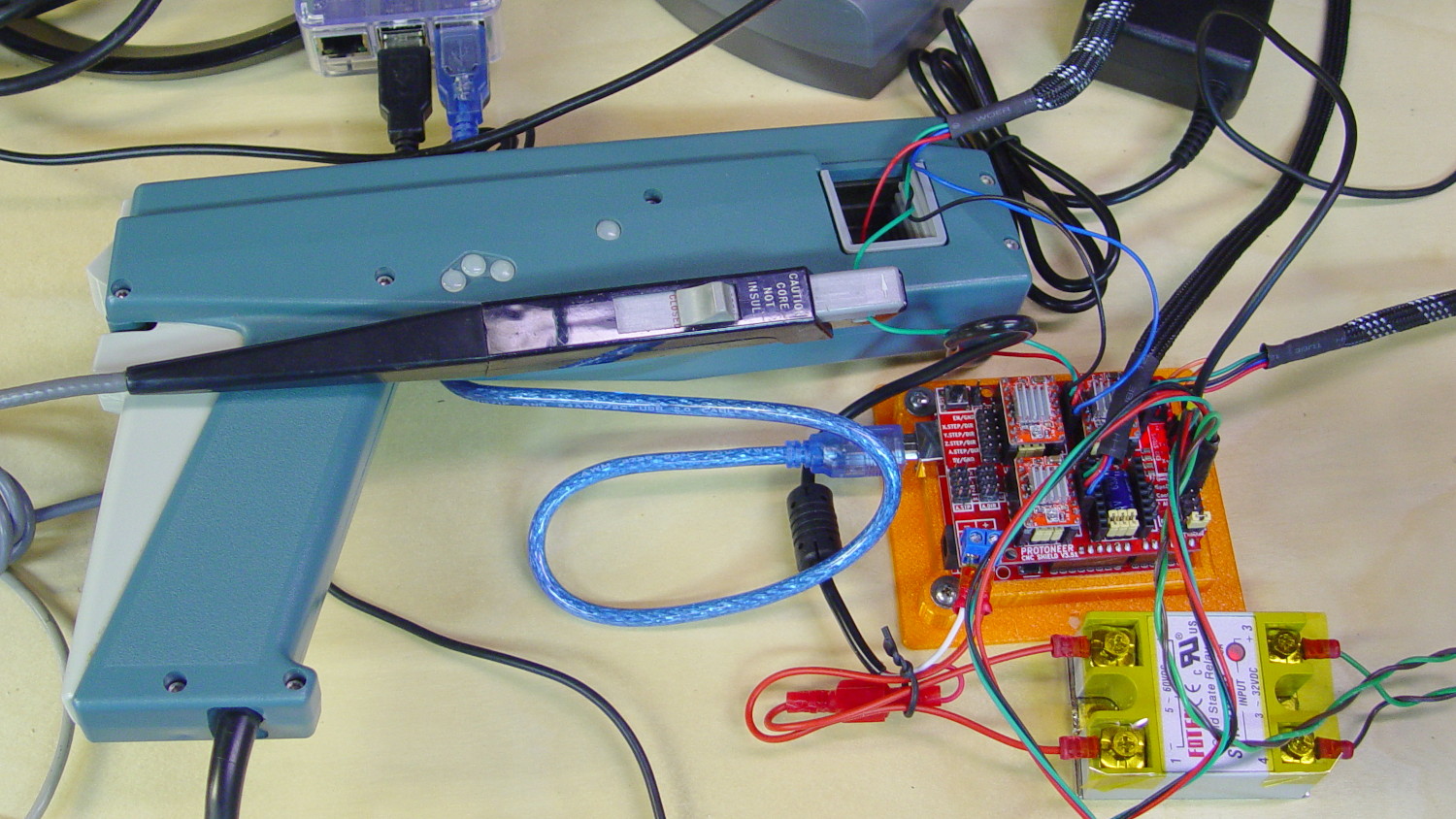
    The default DRV8825 driver configuration uses 1:32 microstepping, which I thought was excessive. I replaced the stock RAMPS setup with a Protoneer / GRBL setup using A4988 drivers in 1:16 microstepping mode, got it configured, and made a few measurements:

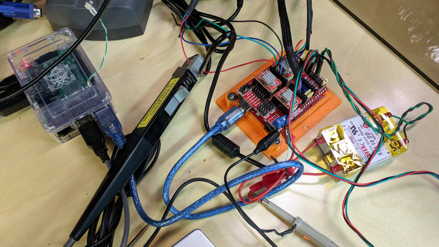
    MPCNC CNC Shield - Current Measurement Setup
    MPCNC CNC Shield – Current Measurement Setup

    The current probe measures the winding current in the red wire. The voltage probe at the bottom isn’t doing anything, because I ran out of hands.

    Here’s a 10 mm X axis move at 3600 mm/min = 60 mm/s:

    MPCNC X 10mm 60mm-s 500mA-div
    MPCNC X 10mm 60mm-s 500mA-div

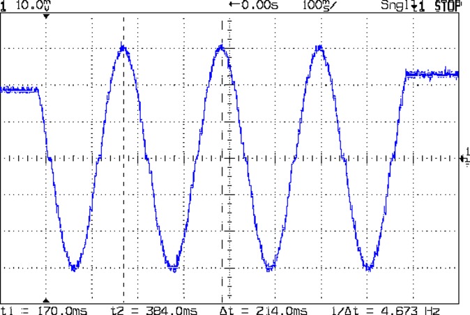
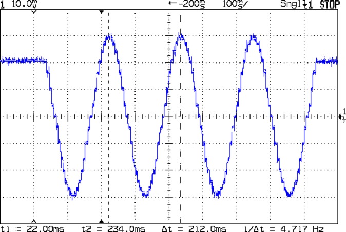
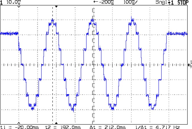
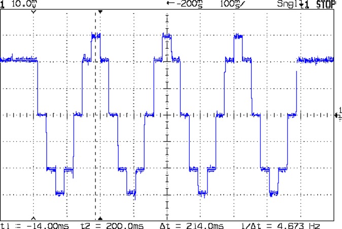
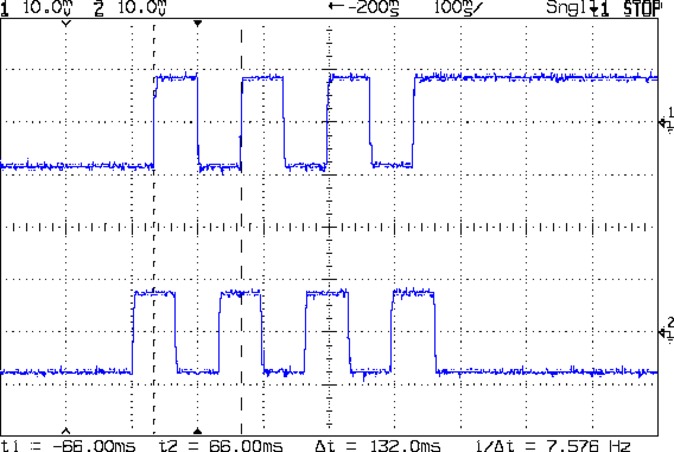
    The top trace shows the winding current at 500 mA/div. The bottom trace shows the voltage applied to the winding at the A4988 driver pin.

    Basically, the +12 V supply doesn’t provide enough headroom to let the driver force the required current into the winding at full speed, which is why the peak current decreases as the step rate increases and the sinusoid becomes a square(-ish) wave. The applied voltage switches rapidly to maintain the proper winding current when the axis is stationary or moving slowly (where the driver’s PWM current control works fine), but turns into a square (well, rectangular) wave as the pace picks up (and the driver loses control of the current).

    The motor drives a 16 tooth pulley with a 2 mm belt pitch, so each revolution moves 32 mm of belt. With 1:16 microstepping, each revolution requires 3200 = 200 full step × 16 microstep/step pulses, which works out to 100 step/mm = (3200 step/rev) / (32 mm/rev). At the commanded speed near the middle of the trace, the driver must produce 6000 step/s = 60 mm/s × 100 step/mm, so each step lasts 167 μs, about τ/10.

    In round numbers, the first full cycle on the left has a 20 ms period. Each full cycle = 4 full steps = 64 microsteps, so the belt moved (60 step) / (100 step/mm) = 0.6 mm, at an (average) speed of 30 mm/s = 1800 mm/min. The current begins to fall off by the third cycle with a 12 ms period, a pace of 50 mm/s = 3000 mm/s, and pretty much falls off a cliff by 60 mm/s in the middle.

    To be fair, those are aggressive speeds for milling, but lasers and 3D printers tick along pretty quickly, so they’re not unreasonable.

    More study is indicated, as the saying goes …

  • Sandisk 32 GB High Endurance Video Monitoring Card

    Despite my misgivings, “Ships from and sold by Amazon.com” suggests I could return a Sandisk 32 GB High Endurance MicroSD card if things turned out badly:

    MicroSD 32 GB - Samsung EVO and SanDisk High Endurance
    MicroSD 32 GB – Samsung EVO and SanDisk High Endurance

    Unlike the Samsung cards, Sandisk charges a substantial premium for not buying through Amazon.

    Verifying the card using f3probe produced the same results as with the earlier 64 GB card and copying the existing files from the Fly6 card (on the left) went smoothly:

    
    rsync -rtv /mnt/Fly6/ /mnt/part


    “High Endurance” means it’s rated for 5000 hours of “Full HD” recording, which they think occurs at 26 Mb/s. The Fly6 records video in 10 minutes chunks, each weighing about 500 MB, call it 1 MB/s = 8 Mb/s, a third of their nominal pace. One might reasonably expect this card to outlive the camera.

    As with the AS30V, we shall see …

  • Compact Fluorescent Bulb Autopsy

    I fished the failed CFL bulb from the recycling box:

    Failed CFL - case damage
    Failed CFL – case damage

    The straight-ish crack between the tube ends looks like it happened as the (yellowed) plastic ruptured and hardened.

    Not wanting to get a face full of glass fragments spiced with metallic mercury, I wrapped a blast shield around the spiral tube:

    Failed CFL - tube wrap - shattered base
    Failed CFL – tube wrap – shattered base

    The terminal ends fit loosely in the crumbling base at the start of this operation, leaving the tube wobbling above the base. The plastic cracked as I wrapped the tube, so, for lack of anything smarter, I applied a pin punch to break away the rest of the upper base.

    The tube doesn’t fit into a socket, of course, and terminates in four wire connections:

    Failed CFL - tube terminals
    Failed CFL – tube terminals

    Those wires pass through notches on the edge of the PCB, bend around the board, pass through vias, and get soldered to pads. The solder side faces the tube, with all the components nestled into the base toward the screw terminals:

    Failed CFL - PCB solder side faces upward
    Failed CFL – PCB solder side faces upward

    The component side sports a surprising number of parts:

    Failed CFL - PCB components - 2
    Failed CFL – PCB components – 2

    A view from the other direction, where you can see the tube wires curling around the edge:

    Failed CFL - PCB components - 1
    Failed CFL – PCB components – 1

    I generally harvest inductors & suchlike, but it got really really hot in there and, methinks, cooked the life out of the parts:

    Failed CFL - overheated capacitor
    Failed CFL – overheated capacitor

    The PCB date code stamp could be “730”, suggesting either 1997 or 2007. In any event, it’s been a while.

    I hope LED bulbs outlast these things, but I have my doubts …


  • Samsung EVO Plus 32 GB MicroSD Cards: Verification

    A pair of known-good MicroSD cards arrived direct from Samsung at a surprisingly slight premium over the junk available on Amazon:

    Samsung EVO Plus MicroSD - 32 GB
    Samsung EVO Plus MicroSD – 32 GB

    f3probe reported they’re OK, which is no surprise:

    sudo f3probe --time-ops /dev/sdc
    F3 probe 6.0
    Copyright (C) 2010 Digirati Internet LTDA.
    This is free software; see the source for copying conditions.
    
    WARNING: Probing normally takes from a few seconds to 15 minutes, but
             it can take longer. Please be patient.
    
    Probe finished, recovering blocks... Done
    
    Good news: The device `/dev/sdc' is the real thing
    
    Device geometry:
    	         *Usable* size: 29.81 GB (62521344 blocks)
    	        Announced size: 29.81 GB (62521344 blocks)
    	                Module: 32.00 GB (2^35 Bytes)
    	Approximate cache size: 0.00 Byte (0 blocks), need-reset=no
    	   Physical block size: 512.00 Byte (2^9 Bytes)
    
    Probe time: 2'04"
     Operation: total time / count = avg time
          Read: 51.79s / 4197134 = 12us
         Write: 1'10" / 4192321 = 16us
         Reset: 1.41s / 1 = 1.41s
    

    These will go into Raspberry Pi projects, where their huge capacity won’t produce any benefit. It seems one can’t get known-good, small cards these days.

    I don’t see much point in buying known-crap counterfeits on Amazon, given their commingled-storage problem as pointed out by their helpful FBA advice:

    Use the manufacturer barcode to track inventory

    By default, your seller account is set to use the manufacturer barcode to track your eligible inventory throughout the Amazon fulfillment process. You can change this default barcode preference at any time. You have the option to change your barcode preference for each offer you create. You can also change your barcode preference for a product when you change a listing from Fulfilled by Merchant to Fulfilled by Amazon.

    Important: Items in your inventory that are identified and tracked using manufacturer barcodes are commingled with items of the same products from other sellers who also use manufacturer barcodes for those items.

    If you choose to use manufacturer barcodes, when customers purchase a product from you, Amazon can send the item that is closest to them, even if you didn’t send it to the fulfillment center. When that happens, you get the credit for the sale, and we transfer an item from your inventory to the seller whose inventory was used to fulfill the order. In addition, if you use the manufacturer barcode, you don’t have to apply an Amazon barcode to each item yourself.

    Even though inventory tracked using the manufacturer barcode is commingled within the network, the source of the inventory is tracked by our fulfillment systems and is taken into consideration if inventory problems arise.

  • Makerbot-style Endstop Power Adapter for Protoneer Arduino CNC Shield

    The Protoneer Arduino CNC shield (*) has a row of 2-pin headers for bare endstop switches. Being a big fan of LED Blinkiness, I have a stock of 3-pin Makerbot-style mechanical endstops that require a +5 V connection in addition to ground and the output.

    A crude-but-effective adapter consists of half a dozen header pins soldered to a length of stout copper wire, with a pigtail to a +5 V pin elsewhere on the board:

    3-pin to 2-pin Endstop Power Adapter
    3-pin to 2-pin Endstop Power Adapter

    A closer look:

    3-pin to 2-pin Endstop Power Adapter - detail
    3-pin to 2-pin Endstop Power Adapter – detail

    The pins get trimmed on the other side of the bus wire, because they don’t go through the PCB.

    Installed on the board, it doesn’t look like much:

    3-pin endstop adapter on Prontoneer board
    3-pin endstop adapter on Prontoneer board

    Looks like it needs either Kapton tape or epoxy, doesn’t it?

    Three more endstops at the far end of the MPCNC rails (for hard limits) will fill the unused header pins.

    (*) It’s significantly more expensive than the Chinese knockoffs, but in this case I cheerfully pay to support the guy: good stuff, direct from the source.

  • Prototype Board Holder: Now With Mounting Holes and Common Board Sizes

    The folks I’ve been coaching through their plotter build project showed it off at the local MiniMakerFaire this past weekend. Next time around, I’ll insist they secure their circuit boards and use good wiring techniques, so as to avoid destroying more stepper drivers.

    To that end, adding mounting holes to my proto board holder seems in order:

    Proto Board Holder 90x70 - Flange mounting holes - Slic3r preview
    Proto Board Holder 90×70 – Flange mounting holes – Slic3r preview

    The board dimensions now live in an associative array, so you just pick the board name from a Configurator drop-down list:

    /* [Options] */
    
    PCBSelect = "ArdUno"; // ["20x80","40x60","30x70","50x70","70x90","80x120","ArdDuemil","ArdMega","ArdPro","ArdUno","ProtoneerCNC"]
    
    PCB_NAME = 0;
    PCB_DIMENSION = 1;
    
    PCBSizes = [
      ["40x60",[40,60,1.6]],
      ["30x70",[30,70,1.6]],
      ["50x70",[50,70,1.6]],
      ["20x80",[20,80,1.6]],
      ["70x90",[70,90,1.6]],
      ["80x120",[80,120,1.6]],
      ["ArdDuemil",[69,84,1.6]],
      ["ArdMega",[102,53.5,1.6]],
      ["ArdPro",[53,53.5,1.6]],
      ["ArdUno",[69,53.1,1.6]],
      ["ProtoneerCNC",[69,53.1,1.6]],
    ];
    

    Which seems easier than keeping track of the dimensions in comments.

    You can now put the PCB clamp screws and mounting holes on specific corners & sides, allowing oddball locations for Arduino boards with corner cutouts along the right edge:

    Proto Board Holder ArdUno - Slic3r preview
    Proto Board Holder ArdUno – Slic3r preview

    A “selector” notation separates the hole location from the board dimensions & coordinates:

    ScrewSites = [
    //  [-1,1],[1,1],[1,-1],[-1,-1],        // corners
    //  [-1,0],[1,0],[0,1],[0,-1]           // middles
      [-1,1],[-1,-1],[1,0]                  // Arduinos
    ];
    

    Might not be most obvious way, but it works for me. Most of the time, corner clamps seem just fine, so I’m not sure adding the clamp and mounting hole locations to the dimension array makes sense.

    The OpenSCAD source code as a GitHub Gist:

    // Test support frame for proto boards
    // Ed Nisley KE4ZNU – Jan 2017
    // June 2017 – Add side-mount bracket, inserts into bottom
    // 2017-11 – Selectable board sizes, chassis mounting holes
    /* [Options] */
    PCBSelect = "ArdUno"; // ["20×80","40×60","30×70","50×70","70×90","80×120","ArdDuemil","ArdMega","ArdPro","ArdUno","ProtoneerCNC"]
    Layout = "Frame"; // [Frame, Bracket]
    ClampFlange = true; // external flange
    Mounts = true; // frame to chassis screw holes
    Channel = false; // wiring channel cutout
    WasherRecess = false; // cutout around screw head
    /* [Extrusion parameters] */
    ThreadThick = 0.25; // [0.15, 0.20, 0.25]
    ThreadWidth = 0.40;
    function IntegerMultiple(Size,Unit) = Unit * ceil(Size / Unit);
    /* [Hidden] */
    Protrusion = 0.1;
    HoleWindage = 0.2;
    inch = 25.4;
    Tap4_40 = 0.089 * inch;
    Clear4_40 = 0.110 * inch;
    Head4_40 = 0.211 * inch;
    Head4_40Thick = 0.065 * inch;
    Nut4_40Dia = 0.228 * inch;
    Nut4_40Thick = 0.086 * inch;
    Washer4_40OD = 0.270 * inch;
    Washer4_40ID = 0.123 * inch;
    Tap6_32 = 0.106 * inch;
    Clear6_32 = 0.166 * inch;
    Head6_32 = 0.251 * inch;
    Head6_32Thick = 0.097 * inch;
    Nut6_32Dia = 0.312 * inch;
    Nut6_32Thick = 0.109 * inch;
    Washer6_32OD = 0.361 * inch;
    Washer6_32ID = 0.156 * inch;
    ID = 0;
    OD = 1;
    LENGTH = 2;
    //- PCB sizes
    // the list must contain all the selection names as above
    //* [Hidden] */
    PCB_NAME = 0;
    PCB_DIMENSION = 1;
    PCBSizes = [
    ["40×60",[40,60,1.6]],
    ["30×70",[30,70,1.6]],
    ["50×70",[50,70,1.6]],
    ["20×80",[20,80,1.6]],
    ["70×90",[70,90,1.6]],
    ["80×120",[80,120,1.6]],
    ["ArdDuemil",[69,84,1.6]],
    ["ArdMega",[102,53.5,1.6]],
    ["ArdPro",[53,53.5,1.6]],
    ["ArdUno",[69,53.1,1.6]],
    ["ProtoneerCNC",[69,53.1,1.6]],
    ];
    PCBIndex = search([PCBSelect],PCBSizes)[0];
    PCBSize = PCBSizes[PCBIndex][PCB_DIMENSION];
    //echo(str("PCB Size Table: ",PCBSizes));
    //echo(str("PCB Select: ",PCBSelect));
    //echo(str("PCB Index: ",PCBIndex));
    echo(str("PCB Size: ",PCBSize));
    /* [Sizes] */
    WallThick = 4.0; // basic frame structure
    FrameHeight = 10.0;
    /* [Hidden] */
    Insert = [3.9,4.6,5.8];
    PCBShelf = 1.0; // width of support rim under PCB
    Clearance = 1*[ThreadWidth,ThreadWidth,0]; // around PCB on all sides
    ScrewOffset = ThreadWidth + Insert[OD]/2; // beyond PCB edges
    echo(str("Screw offset: ",ScrewOffset));
    /* [Screw Selectors] */
    // ij selectors for PCB clamp screw holes: -1/0/1 = left/center/right , bottom/center/top
    ScrewSites = [
    // [-1,1],[1,1],[1,-1],[-1,-1], // corners
    // [-1,0],[1,0],[0,1],[0,-1] // middles
    [-1,1],[-1,-1],[1,0] // Arduinos
    ];
    // ij selectors for frame mounting holes
    MountSites = [
    [0,-1],[0,1],
    // [-1,0],[1,0]
    ];
    function ScrewAngle(ij) = (ij[0]*ij[1]) ? ij[0]*ij[1]*15 : ((!ij[1]) ? 30 : 0); // align screw sides
    OAHeight = FrameHeight + Clearance[2] + PCBSize[2]; // total frame height
    echo(str("OAH: ",OAHeight));
    BossOD = 2*Washer4_40OD; // make bosses oversized for washers
    FlangeExtension = 4.0 + Washer6_32OD/2 – WallThick; // beyond frame structure
    FlangeThick = IntegerMultiple(2.0,ThreadThick); // plate under frame
    Flange = PCBSize
    + 2*[ScrewOffset,ScrewOffset,0]
    + [BossOD,BossOD,0]
    + [2*FlangeExtension,2*FlangeExtension,(FlangeThick – PCBSize[2])]
    ;
    FlangeRadius = BossOD/4;
    echo(str("Flange: ",Flange));
    NumSides = 4*5;
    WireChannel = [Flange[0],15.0,3.0 + PCBSize[2]]; // ad-hoc wiring cutout
    WireChannelOffset = [
    Flange[0]/2,0,(FrameHeight + PCBSize[2] – WireChannel[2]/2)
    ];
    //- Adjust hole diameter to make the size come out right
    module PolyCyl(Dia,Height,ForceSides=0) { // based on nophead's polyholes
    Sides = (ForceSides != 0) ? ForceSides : (ceil(Dia) + 2);
    FiiDia = Dia / cos(180/Sides);
    cylinder(r=(FiiDia + HoleWindage)/2,h=Height,$fn=Sides);
    }
    //- Build things
    if (Layout == "Frame")
    difference() {
    union() { // body block
    translate([0,0,OAHeight/2])
    cube(PCBSize + Clearance + [2*WallThick,2*WallThick,FrameHeight],center=true);
    for (ij = ScrewSites) // screw bosses
    if (ij[0] != 0 || ij[1] != 0)
    translate([ij[0]*(PCBSize[0]/2 + ScrewOffset),
    ij[1]*(PCBSize[1]/2 + ScrewOffset),
    0])
    cylinder(d=BossOD,h=OAHeight,$fn=NumSides);
    if (ClampFlange) // flange for work holder & mounting screw holes
    linear_extrude(height=Flange[2])
    hull()
    for (i=[-1,1], j=[-1,1]) {
    translate([i*(Flange[0]/2 – FlangeRadius),j*(Flange[1]/2 – FlangeRadius)])
    circle(r=FlangeRadius,$fn=NumSides); // convenient rounding size
    }
    }
    for (ij = ScrewSites) { // screw position indeies
    if (ij[0] != 0 || ij[1] != 0) {
    translate([ij[0]*(PCBSize[0]/2 + ScrewOffset),
    ij[1]*(PCBSize[1]/2 + ScrewOffset),
    -Protrusion])
    rotate(ScrewAngle(ij))
    PolyCyl(Clear4_40,(OAHeight + 2*Protrusion),6); // screw clearance holes
    translate([ij[0]*(PCBSize[0]/2 + ScrewOffset),
    ij[1]*(PCBSize[1]/2 + ScrewOffset),
    -Protrusion])
    rotate(ScrewAngle(ij))
    PolyCyl(Insert[OD],OAHeight – PCBSize[2] – 3*ThreadThick + Protrusion,6); // inserts
    if (WasherRecess)
    translate([ij[0]*(PCBSize[0]/2 + ScrewOffset),
    ij[1]*(PCBSize[1]/2 + ScrewOffset),
    OAHeight – PCBSize[2]])
    PolyCyl(1.2*Washer4_40OD,(PCBSize[2] + Protrusion),NumSides); // optional washer recess
    }
    }
    if (Mounts)
    for (ij = MountSites)
    translate([ij[0]*(Flange[0]/2 – Washer6_32OD/2),ij[1]*(Flange[1]/2 – Washer6_32OD/2),-Protrusion])
    rotate(ScrewAngle(ij))
    PolyCyl(Clear6_32,(Flange[2] + 2*Protrusion),6);
    translate([0,0,OAHeight/2]) // through hole below PCB
    cube(PCBSize – 2*[PCBShelf,PCBShelf,0] + [0,0,2*OAHeight],center=true);
    translate([0,0,(OAHeight – (PCBSize[2] + Clearance[2])/2 + Protrusion/2)]) // PCB pocket on top
    cube(PCBSize + Clearance + [0,0,Protrusion],center=true);
    if (Channel)
    translate(WireChannelOffset) // opening for wires from bottom side
    cube(WireChannel + [0,0,Protrusion],center=true);
    }
    // Add-on bracket to hold smaller PCB upright at edge
    PCB2Insert = [3.0,4.9,4.1];
    PCB2OC = 45.0;
    if (Layout == "Bracket")
    difference() {
    hull() // frame body block
    for (i=[-1,1]) // bosses around screws
    translate([i*(PCBSize[0]/2 + ScrewOffset),0,0])
    cylinder(r=Washer4_40OD,h=OAHeight,$fn=NumSides);
    for (i=[-1,1]) // frame screw holes
    translate([i*(PCBSize[0]/2 + ScrewOffset),0,-Protrusion])
    rotate(i*180/(2*6))
    PolyCyl(Clear4_40,(OAHeight + 2*Protrusion),6);
    for (i=[-1,1]) // PCB insert holes
    translate([i*PCB2OC/2,(Washer4_40OD + Protrusion),OAHeight/2])
    rotate([90,0,0])
    cylinder(d=PCB2Insert[OD],h=2*(Washer4_40OD + Protrusion),$fn=6);
    }
  • Ham-It-Up Test Signal Source: Simulation

    Rather than bestir myself to measure the Test Signal Source on the Ham-It-Up upconverter:

    Ham-It-Up Test Signal source - LTSpice schematic
    Ham-It-Up Test Signal source – LTSpice schematic

    The 74LVC2G14 Schmitt-Trigger Inverter datasheet supplies useful parameters:

    Ham-It-Up Test Signal source - LTSpice Schmitt params
    Ham-It-Up Test Signal source – LTSpice Schmitt params

    All of which come together and produce a waveform (clicky for more dots):

    Ham-It-Up Test Signal source - LTSpice waveform
    Ham-It-Up Test Signal source – LTSpice waveform

    Which suggests the Test Signal ticks along at tens-of-MHz, rather than the tens-of-kHz I expected from the birdies in the filtered 60 kHz preamp response.

    Of course, hell hath no fury like that of an unjustified assumption, so actually measuring the waveform would verify the cap value and similar details.