|
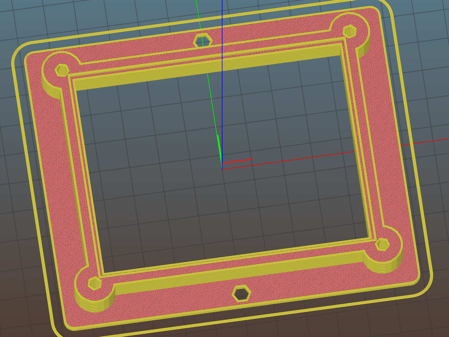
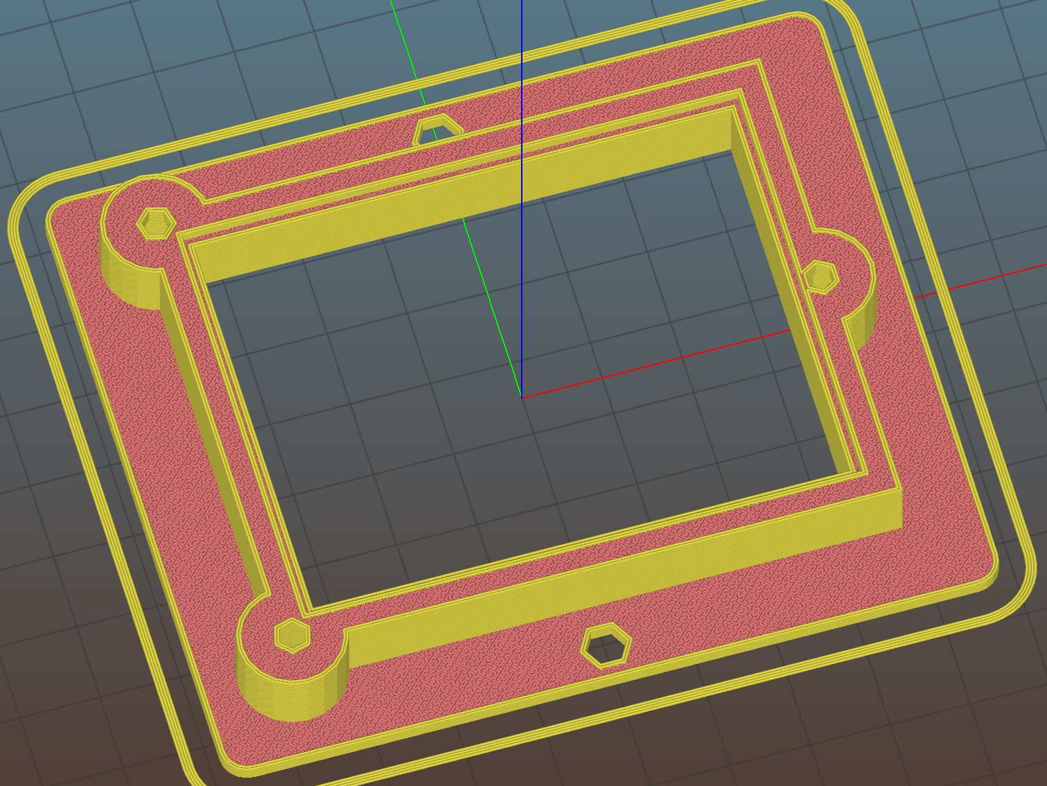
// Test support frame for proto boards |
|
// Ed Nisley KE4ZNU – Jan 2017 |
|
// June 2017 – Add side-mount bracket, inserts into bottom |
|
// 2017-11 – Selectable board sizes, chassis mounting holes |
|
|
|
/* [Options] */ |
|
|
|
PCBSelect = "ArdUno"; // ["20×80","40×60","30×70","50×70","70×90","80×120","ArdDuemil","ArdMega","ArdPro","ArdUno","ProtoneerCNC"] |
|
|
|
Layout = "Frame"; // [Frame, Bracket] |
|
|
|
ClampFlange = true; // external flange |
|
|
|
Mounts = true; // frame to chassis screw holes |
|
|
|
Channel = false; // wiring channel cutout |
|
|
|
WasherRecess = false; // cutout around screw head |
|
|
|
/* [Extrusion parameters] */ |
|
|
|
ThreadThick = 0.25; // [0.15, 0.20, 0.25] |
|
ThreadWidth = 0.40; |
|
|
|
function IntegerMultiple(Size,Unit) = Unit * ceil(Size / Unit); |
|
|
|
/* [Hidden] */ |
|
|
|
Protrusion = 0.1; |
|
|
|
HoleWindage = 0.2; |
|
|
|
inch = 25.4; |
|
|
|
Tap4_40 = 0.089 * inch; |
|
Clear4_40 = 0.110 * inch; |
|
Head4_40 = 0.211 * inch; |
|
Head4_40Thick = 0.065 * inch; |
|
Nut4_40Dia = 0.228 * inch; |
|
Nut4_40Thick = 0.086 * inch; |
|
Washer4_40OD = 0.270 * inch; |
|
Washer4_40ID = 0.123 * inch; |
|
|
|
Tap6_32 = 0.106 * inch; |
|
Clear6_32 = 0.166 * inch; |
|
Head6_32 = 0.251 * inch; |
|
Head6_32Thick = 0.097 * inch; |
|
Nut6_32Dia = 0.312 * inch; |
|
Nut6_32Thick = 0.109 * inch; |
|
Washer6_32OD = 0.361 * inch; |
|
Washer6_32ID = 0.156 * inch; |
|
|
|
ID = 0; |
|
OD = 1; |
|
LENGTH = 2; |
|
|
|
//- PCB sizes |
|
// the list must contain all the selection names as above |
|
|
|
//* [Hidden] */ |
|
PCB_NAME = 0; |
|
PCB_DIMENSION = 1; |
|
|
|
PCBSizes = [ |
|
["40×60",[40,60,1.6]], |
|
["30×70",[30,70,1.6]], |
|
["50×70",[50,70,1.6]], |
|
["20×80",[20,80,1.6]], |
|
["70×90",[70,90,1.6]], |
|
["80×120",[80,120,1.6]], |
|
["ArdDuemil",[69,84,1.6]], |
|
["ArdMega",[102,53.5,1.6]], |
|
["ArdPro",[53,53.5,1.6]], |
|
["ArdUno",[69,53.1,1.6]], |
|
["ProtoneerCNC",[69,53.1,1.6]], |
|
]; |
|
|
|
PCBIndex = search([PCBSelect],PCBSizes)[0]; |
|
PCBSize = PCBSizes[PCBIndex][PCB_DIMENSION]; |
|
|
|
//echo(str("PCB Size Table: ",PCBSizes)); |
|
//echo(str("PCB Select: ",PCBSelect)); |
|
//echo(str("PCB Index: ",PCBIndex)); |
|
echo(str("PCB Size: ",PCBSize)); |
|
|
|
/* [Sizes] */ |
|
|
|
WallThick = 4.0; // basic frame structure |
|
|
|
FrameHeight = 10.0; |
|
|
|
/* [Hidden] */ |
|
|
|
Insert = [3.9,4.6,5.8]; |
|
|
|
PCBShelf = 1.0; // width of support rim under PCB |
|
|
|
Clearance = 1*[ThreadWidth,ThreadWidth,0]; // around PCB on all sides |
|
|
|
ScrewOffset = ThreadWidth + Insert[OD]/2; // beyond PCB edges |
|
echo(str("Screw offset: ",ScrewOffset)); |
|
|
|
/* [Screw Selectors] */ |
|
|
|
// ij selectors for PCB clamp screw holes: -1/0/1 = left/center/right , bottom/center/top |
|
|
|
ScrewSites = [ |
|
// [-1,1],[1,1],[1,-1],[-1,-1], // corners |
|
// [-1,0],[1,0],[0,1],[0,-1] // middles |
|
[-1,1],[-1,-1],[1,0] // Arduinos |
|
]; |
|
|
|
// ij selectors for frame mounting holes |
|
|
|
MountSites = [ |
|
[0,-1],[0,1], |
|
// [-1,0],[1,0] |
|
]; |
|
|
|
function ScrewAngle(ij) = (ij[0]*ij[1]) ? ij[0]*ij[1]*15 : ((!ij[1]) ? 30 : 0); // align screw sides |
|
|
|
OAHeight = FrameHeight + Clearance[2] + PCBSize[2]; // total frame height |
|
echo(str("OAH: ",OAHeight)); |
|
|
|
BossOD = 2*Washer4_40OD; // make bosses oversized for washers |
|
|
|
FlangeExtension = 4.0 + Washer6_32OD/2 – WallThick; // beyond frame structure |
|
|
|
FlangeThick = IntegerMultiple(2.0,ThreadThick); // plate under frame |
|
|
|
Flange = PCBSize |
|
+ 2*[ScrewOffset,ScrewOffset,0] |
|
+ [BossOD,BossOD,0] |
|
+ [2*FlangeExtension,2*FlangeExtension,(FlangeThick – PCBSize[2])] |
|
; |
|
|
|
FlangeRadius = BossOD/4; |
|
|
|
echo(str("Flange: ",Flange)); |
|
NumSides = 4*5; |
|
|
|
WireChannel = [Flange[0],15.0,3.0 + PCBSize[2]]; // ad-hoc wiring cutout |
|
WireChannelOffset = [ |
|
Flange[0]/2,0,(FrameHeight + PCBSize[2] – WireChannel[2]/2) |
|
]; |
|
|
|
//- Adjust hole diameter to make the size come out right |
|
|
|
module PolyCyl(Dia,Height,ForceSides=0) { // based on nophead's polyholes |
|
|
|
Sides = (ForceSides != 0) ? ForceSides : (ceil(Dia) + 2); |
|
|
|
FiiDia = Dia / cos(180/Sides); |
|
|
|
cylinder(r=(FiiDia + HoleWindage)/2,h=Height,$fn=Sides); |
|
} |
|
|
|
//- Build things |
|
|
|
if (Layout == "Frame") |
|
difference() { |
|
union() { // body block |
|
translate([0,0,OAHeight/2]) |
|
cube(PCBSize + Clearance + [2*WallThick,2*WallThick,FrameHeight],center=true); |
|
|
|
for (ij = ScrewSites) // screw bosses |
|
if (ij[0] != 0 || ij[1] != 0) |
|
translate([ij[0]*(PCBSize[0]/2 + ScrewOffset), |
|
ij[1]*(PCBSize[1]/2 + ScrewOffset), |
|
0]) |
|
cylinder(d=BossOD,h=OAHeight,$fn=NumSides); |
|
|
|
if (ClampFlange) // flange for work holder & mounting screw holes |
|
linear_extrude(height=Flange[2]) |
|
hull() |
|
for (i=[-1,1], j=[-1,1]) { |
|
translate([i*(Flange[0]/2 – FlangeRadius),j*(Flange[1]/2 – FlangeRadius)]) |
|
circle(r=FlangeRadius,$fn=NumSides); // convenient rounding size |
|
} |
|
} |
|
|
|
for (ij = ScrewSites) { // screw position indeies |
|
if (ij[0] != 0 || ij[1] != 0) { |
|
translate([ij[0]*(PCBSize[0]/2 + ScrewOffset), |
|
ij[1]*(PCBSize[1]/2 + ScrewOffset), |
|
-Protrusion]) |
|
rotate(ScrewAngle(ij)) |
|
PolyCyl(Clear4_40,(OAHeight + 2*Protrusion),6); // screw clearance holes |
|
|
|
translate([ij[0]*(PCBSize[0]/2 + ScrewOffset), |
|
ij[1]*(PCBSize[1]/2 + ScrewOffset), |
|
-Protrusion]) |
|
rotate(ScrewAngle(ij)) |
|
PolyCyl(Insert[OD],OAHeight – PCBSize[2] – 3*ThreadThick + Protrusion,6); // inserts |
|
|
|
if (WasherRecess) |
|
translate([ij[0]*(PCBSize[0]/2 + ScrewOffset), |
|
ij[1]*(PCBSize[1]/2 + ScrewOffset), |
|
OAHeight – PCBSize[2]]) |
|
PolyCyl(1.2*Washer4_40OD,(PCBSize[2] + Protrusion),NumSides); // optional washer recess |
|
} |
|
} |
|
|
|
if (Mounts) |
|
for (ij = MountSites) |
|
translate([ij[0]*(Flange[0]/2 – Washer6_32OD/2),ij[1]*(Flange[1]/2 – Washer6_32OD/2),-Protrusion]) |
|
rotate(ScrewAngle(ij)) |
|
PolyCyl(Clear6_32,(Flange[2] + 2*Protrusion),6); |
|
|
|
translate([0,0,OAHeight/2]) // through hole below PCB |
|
cube(PCBSize – 2*[PCBShelf,PCBShelf,0] + [0,0,2*OAHeight],center=true); |
|
|
|
translate([0,0,(OAHeight – (PCBSize[2] + Clearance[2])/2 + Protrusion/2)]) // PCB pocket on top |
|
cube(PCBSize + Clearance + [0,0,Protrusion],center=true); |
|
|
|
if (Channel) |
|
translate(WireChannelOffset) // opening for wires from bottom side |
|
cube(WireChannel + [0,0,Protrusion],center=true); |
|
} |
|
|
|
// Add-on bracket to hold smaller PCB upright at edge |
|
|
|
PCB2Insert = [3.0,4.9,4.1]; |
|
PCB2OC = 45.0; |
|
|
|
if (Layout == "Bracket") |
|
difference() { |
|
hull() // frame body block |
|
for (i=[-1,1]) // bosses around screws |
|
translate([i*(PCBSize[0]/2 + ScrewOffset),0,0]) |
|
cylinder(r=Washer4_40OD,h=OAHeight,$fn=NumSides); |
|
|
|
for (i=[-1,1]) // frame screw holes |
|
translate([i*(PCBSize[0]/2 + ScrewOffset),0,-Protrusion]) |
|
rotate(i*180/(2*6)) |
|
PolyCyl(Clear4_40,(OAHeight + 2*Protrusion),6); |
|
|
|
for (i=[-1,1]) // PCB insert holes |
|
translate([i*PCB2OC/2,(Washer4_40OD + Protrusion),OAHeight/2]) |
|
rotate([90,0,0]) |
|
cylinder(d=PCB2Insert[OD],h=2*(Washer4_40OD + Protrusion),$fn=6); |
|
|
|
} |
|
|