Ed Nisley's Blog: Shop notes, electronics, firmware, machinery, 3D printing, laser cuttery, and curiosities. Contents: 100% human thinking, 0% AI slop.
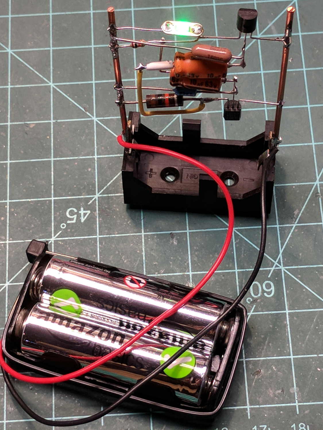
KL17H248-15-4A stepper motor – Back EMF vs RPM – data
Maybe the only questions I ask are ones with linear solutions?
Anyhow, the data comes from the Z-axis motor in the lathe:
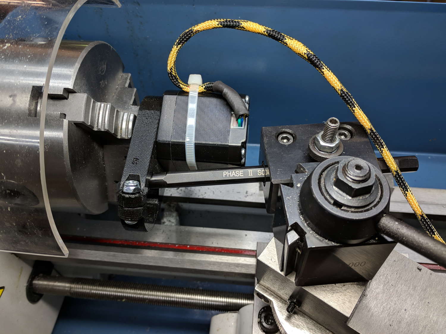
Stepper back EMF test setup
Scary-looking, but reasonably safe. The chuck holds the motor shaft so it’s not going anywhere, the boring bar prevents any rotation, and the motor bearings do exactly what they’re supposed to. Shorting the motor leads would definitely put a hurt on the PLA frame, so I didn’t do that.
The scope sat on the floor beside the lathe, capturing waveforms and doing calculations:
Motor Back EMF – 500 RPM
Some waveforms look bent:
Motor Back EMF – 300 RPM
I asked the scope to measure the RMS voltage, rather than the peak, because it’s less sensitive to distortions.
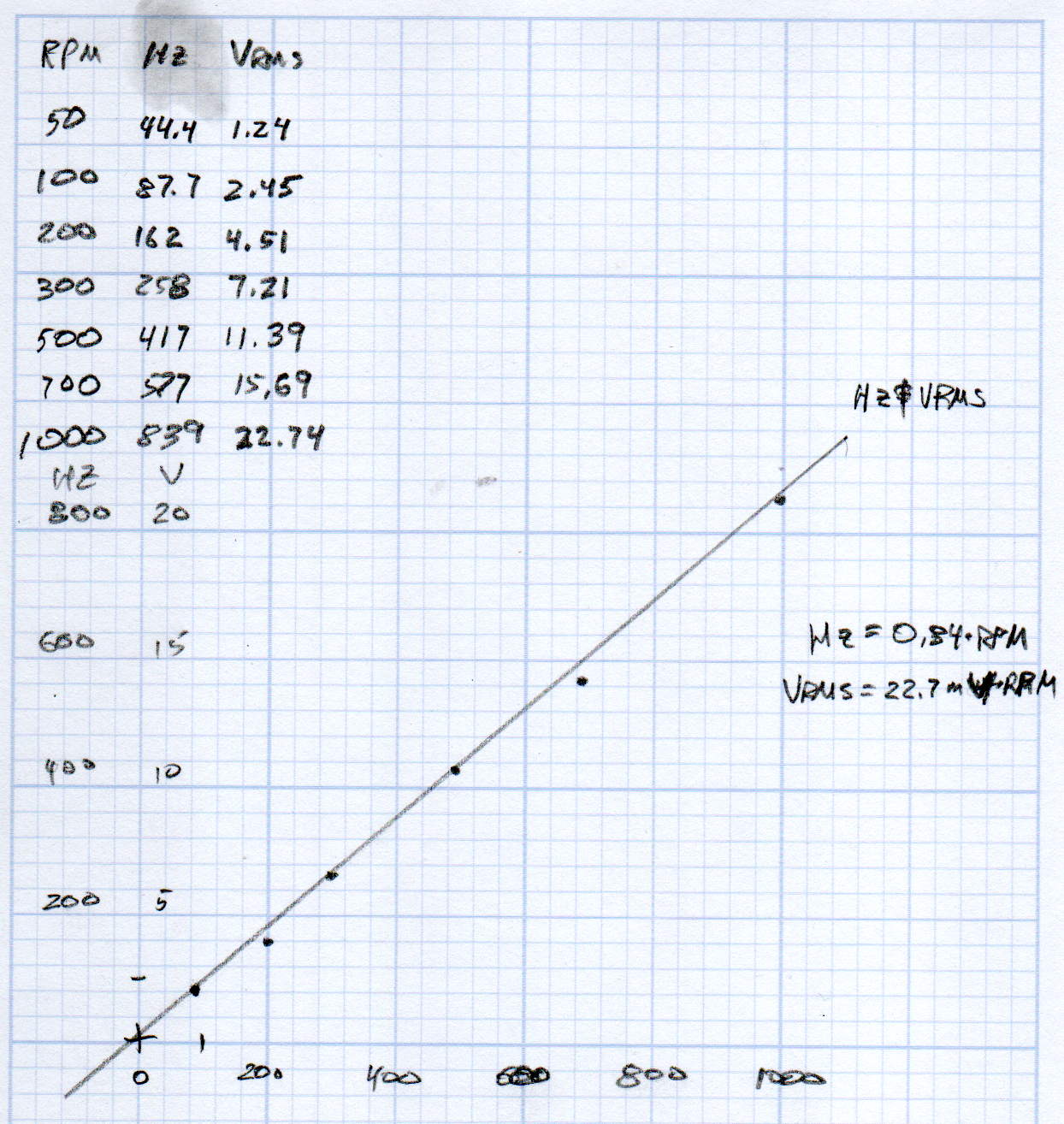
Each winding produces one electrical cycle across four mechanical full steps, with the windings in quadrature. One shaft revolution thus produces 200 / 4 = 50 electrical cycles, so converting from shaft RPM into electrical cycles/s goes a little something like this:
So the shaft turns at 375 RPM when the X axis moves at 12 k mm/min, with each motor generating 8.5 Vrms = 12 Vpk of back EMF.
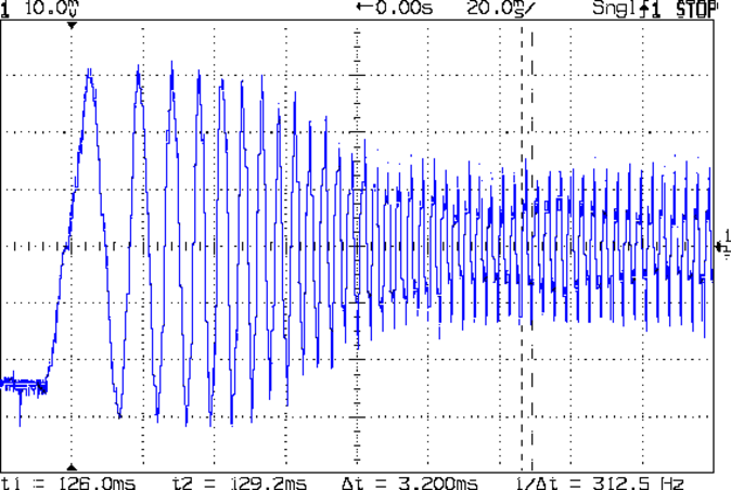
The MPCNC wires the two motors on each axis in series, so the 24 V power supply faces 24 V of back EMF (!) from both motors, leaving exactly nothing to push the winding current around. Because the highest EMF occurs at the zero crossing points of the (normal) winding current, I think the current peaks now occur there, with the driver completely unable to properly shape the current waveform.
What you see in the scope shot is what actually happens: the current stabilizes at a ragged square-ish wave at maybe 300 mA (plus those nasty spikes). More study is needed.
Our long-suffering and much-repairedKenmore clothes dryer didn’t shut off, with the heat on and the timer failing to advance from whatever position we set it to; the clothes were plenty dry and scorching hot. I tried “timed air dry” to eliminate the heater from the problem and found the timer still didn’t advance.
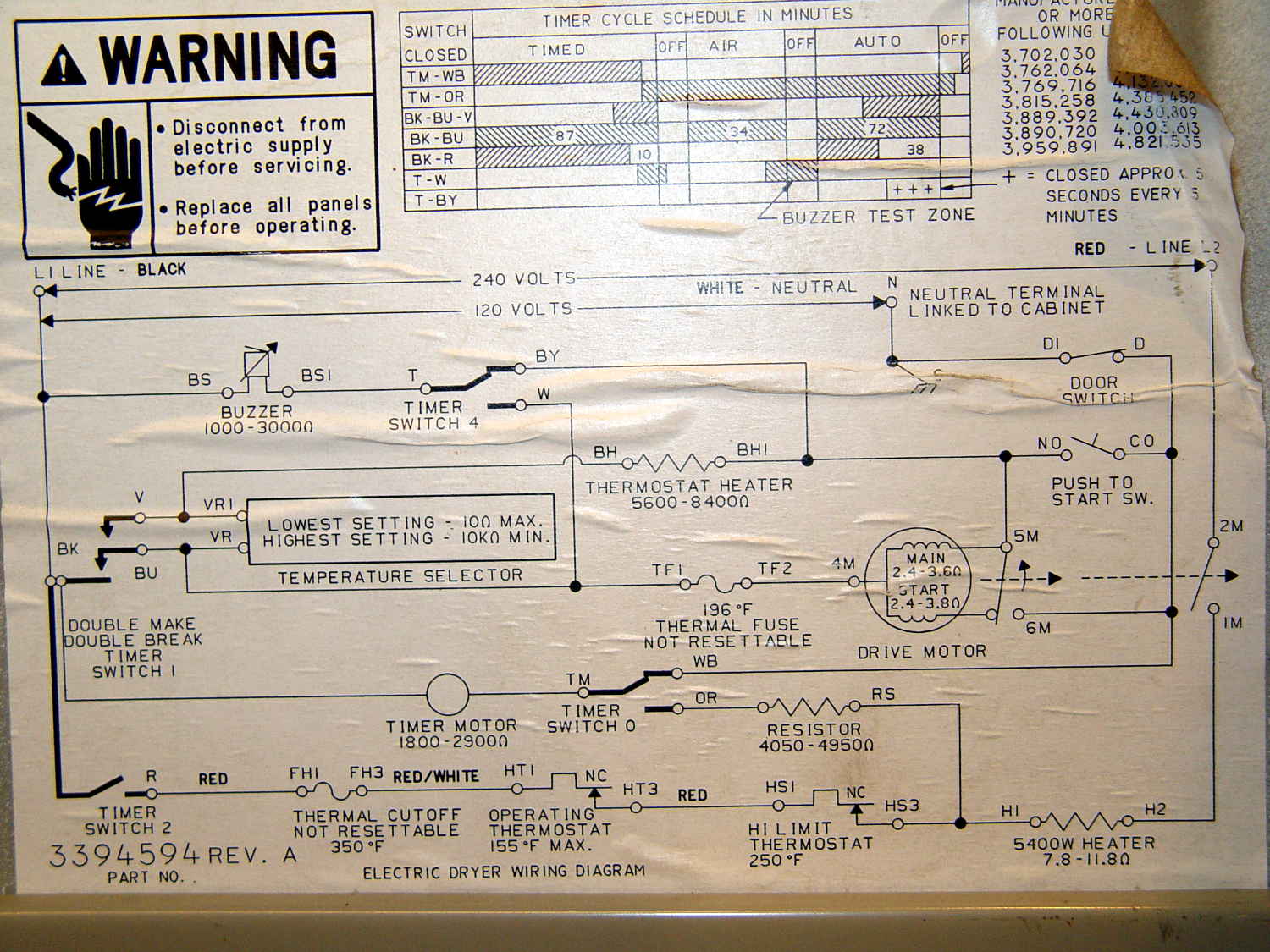
Referring to the wiring diagram may be of some help:
The timer motor is in the next-to-bottom ladder rung. Its BK terminal on the left connects to one side of the 240 VAC supply and the switch just to its right connects terminal TM to either the neutral AC line (thus unbalancing the 240 VAC line by a smidge) or to through a 4-ish kΩ resistor and the heater element (essentially zero, on this scale) to the other hot line; the resistor thus dropping 120-ish VAC.
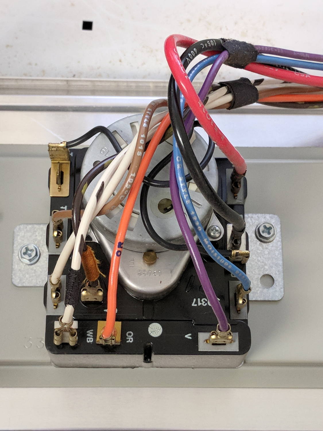
The various switches around the timer collect nearly all the wiring in the dryer:
Kenmore dryer – timer wiring
A closer look at the back, minus all the wiring:
Kenmore dryer – timer backplate
The motor comes off easily enough, revealing the fact that it’s not just an ordinary (i.e., cheap & readily available) timer motor:
Kenmore dryer – timer motor pinions
Hotwiring the motor through a widowmaker zip cord showed it worked just fine. For reference, the upper pinion rotates at about 45 sec/rev, the lower pinion takes maybe 1 hr/rev, both counterclockwise.
Reassembling and hotwiring the complete timer showed it worked just fine, too.
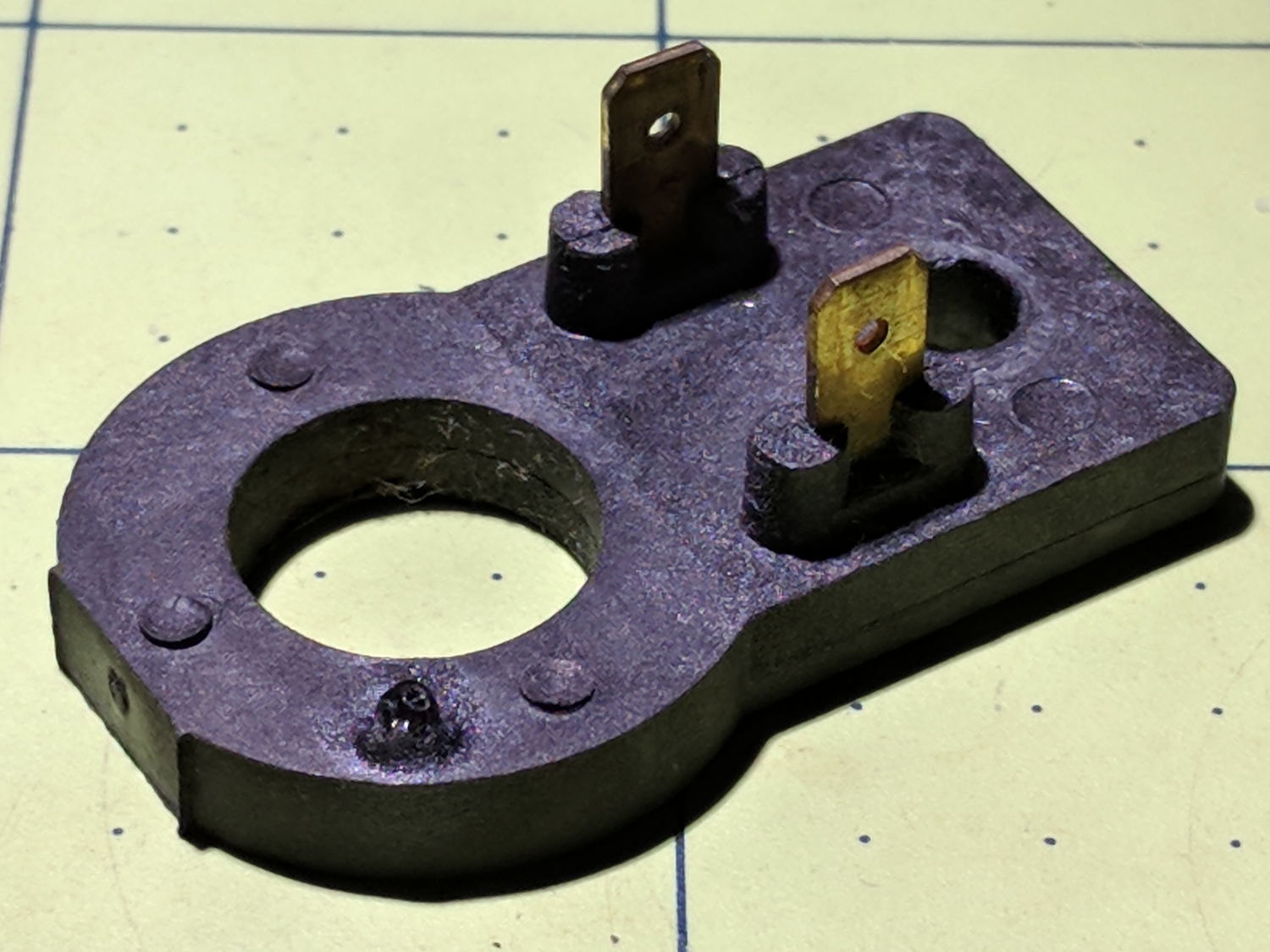
Poring over the wiring diagram suggested the power resistor might be open and, indeed, it was:
Kenmore dryer – power resistor failure
The raised zit near the front shouldn’t be there:
Kenmore dryer – power resistor failure – detail
Apparently, the resistive element broke at that spot, burned through the thermoset plastic case, and failed safe.
Introducing it to Mr Disk Sander revealed a cavity below the zit, surrounded by the remains of the resistive element:
Kenmore dryer – power resistor – cut open
You can get a replacement resistor from the usual suspects for prices between $20 and $40, plus or minus shipping, but their pictures look a lot like an ordinary power resistor inside a length of heatshrink tubing, rather than the molded OEM part. I don’t put much stock in reviews & comments, although they seemed to suggest you get, indeed, an ordinary power resistor.
I didn’t have a 4.7 kΩ power resistor in my (diminished) collection, so I soldered a giant 1.5 kΩ cylindrical resistor in series with a small 3.5 kΩ sandbox, wrapped them up, and tucked them under the front panel’s ground wire:
Kenmore dryer – expedient power resistor
A small box of resistors should arrive in the next month and I’ll re-do the repair with a bit more attention to permanency.
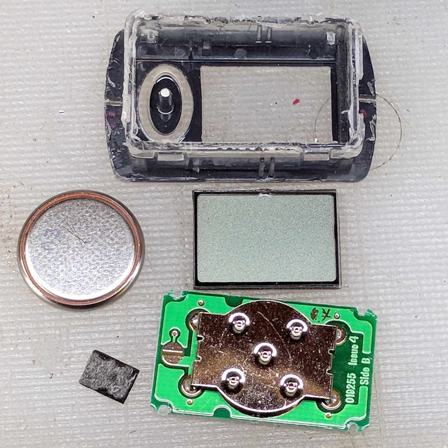
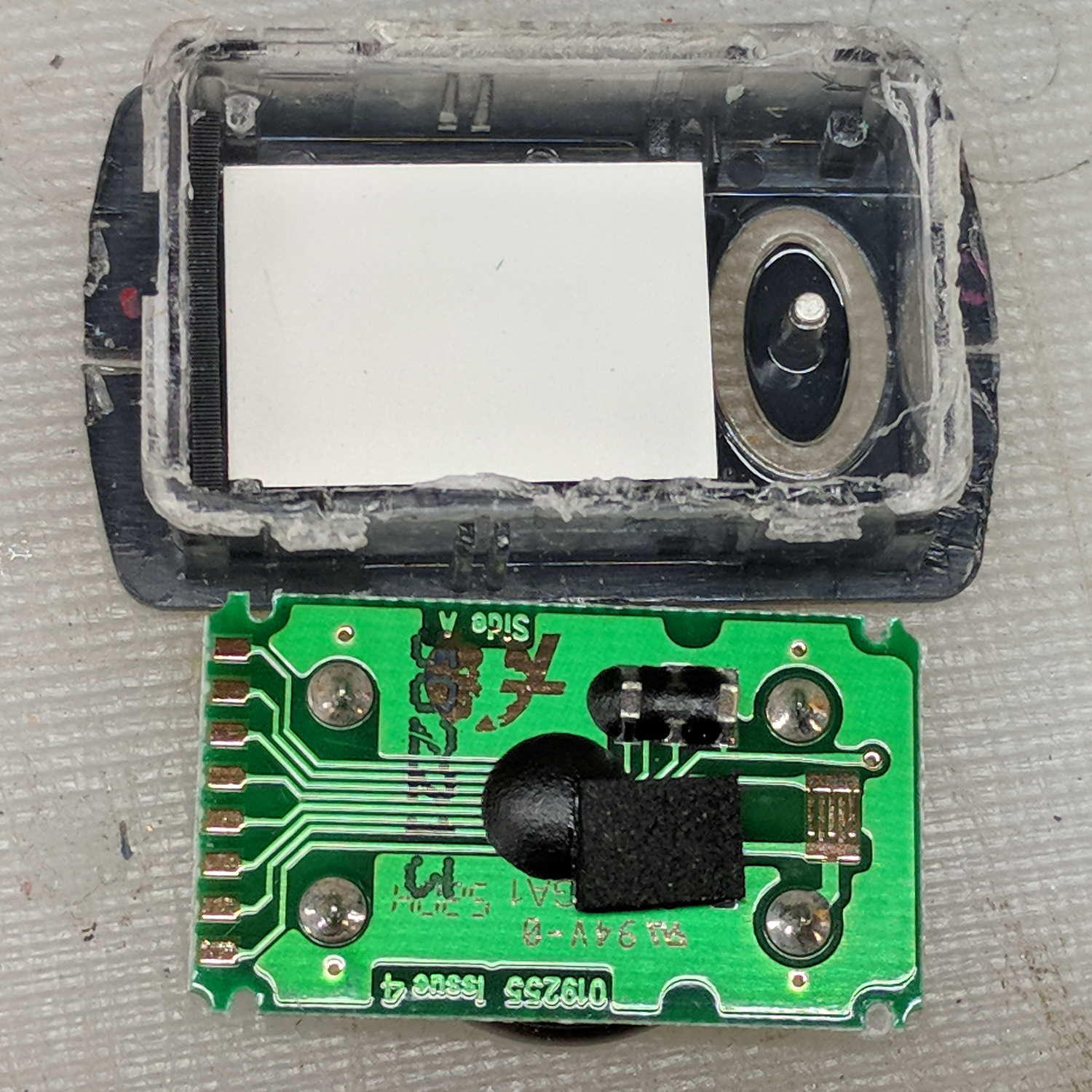
After fartoomanyrepairs, we bought a new Brita pitcher with slightly different, although apparently equally crappy, hinge pins, whereupon I bandsawed the long-failed “smart” filter timer out of the old pitcher’s lid:
Brita pitcher timer – contents
The gray rectangle is the LCD panel showing how long since you last replaced the filter. It died some years ago and, indeed, the CR1616 battery was down to 2.8 V.
However, I think the real failure happened when the black square of conductive foam slipped off the switch contacts under the Reset pushbutton’s stud and went walkabout inside the timer:
Brita pitcher timer – opened
That’s where I found it after sawing the casing open. I think the adhesive side should be stuck to the stud, but we’ll never know.
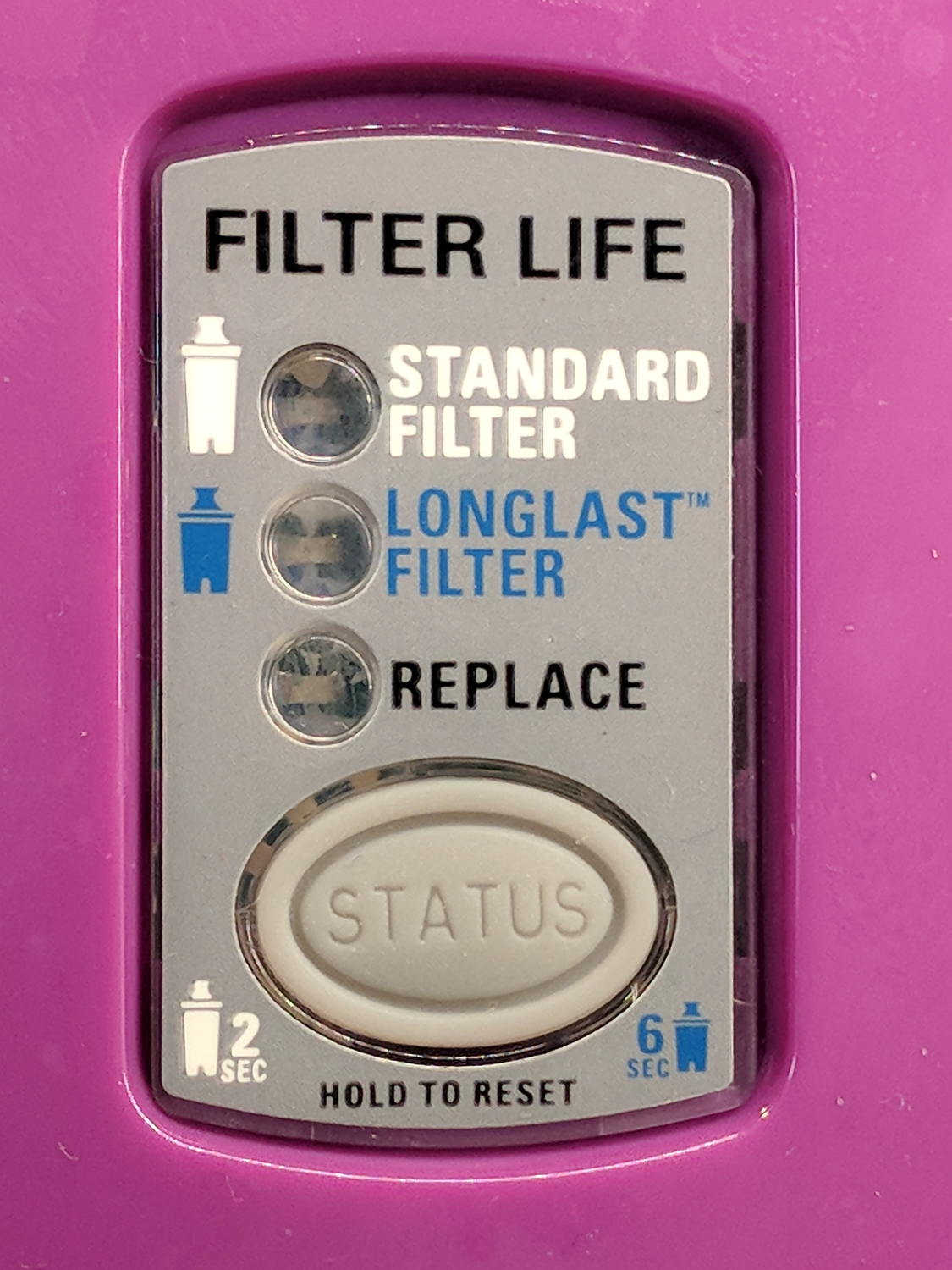
The new pitcher includes a different indicator with green LED status blinkies for “Standard” (40 gallon) and “Longlast” (120 gallon) filter cartridges and a red blinkie for “Expired”:
Brita pitcher – Filter Life counter
Yeah, purple. For some unknown reason, it cost 10% less than the other colors and we’re not fussy.
This one measures filter use by water volume, not elapsed time, counting the number of pitcher refills by noticing when you open the flip-top lid; the corresponding volume depends on your ability to see a nearly invisible line molded into the lid. Unsurprisingly, Longlast filters cost only slightly less than three times standard ones, so they’re not a compelling value proposition.
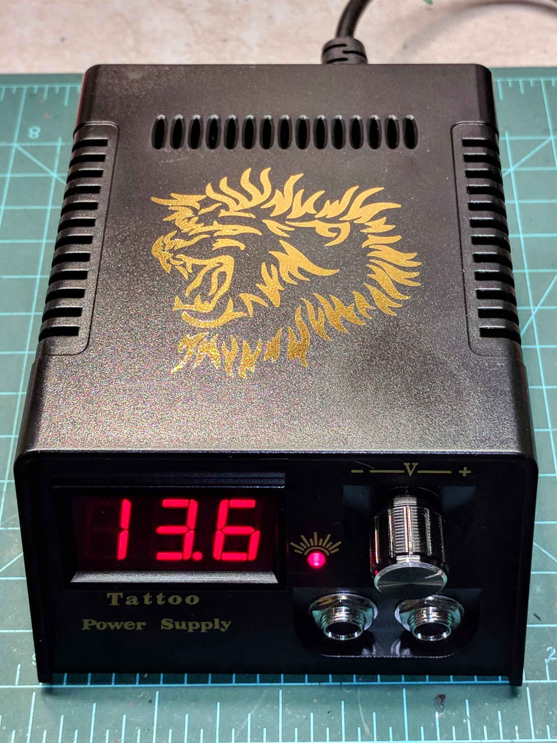
The gold lion really spiffs up the Electronics Workbench!
Somewhat to my surprise, the circuit uses a switching power supply based on a Reactor Micro RM6302 controller that can produce about an amp at voltages up to about 14 V:
Tattoo Digital Power Supply – internal view
CAUTION: Everything on the input side of the transformer runs at line potential. I have my doubts about isolation, particularly under fault conditions.
The trimpot on the PCB seems to adjust the output voltage, although it’s not clear what’s going on.
The three wire AC line cord has a standard IEC entry block on the rear panel, albeit with the ground terminal not connected to anything inside the plastic case. It arrived with the hot wire soldered to a tiny fuse on the PCB and the neutral wire (red!) to the back-panel switch. There being no practical way to put the fuse before the switch, I rewired the hot side to the switch before the fuse and the unswitched neutral to the PCB; that’s as good as it’ll get.
I also flipped the AC switch to put the ON position at the top. Sheesh.
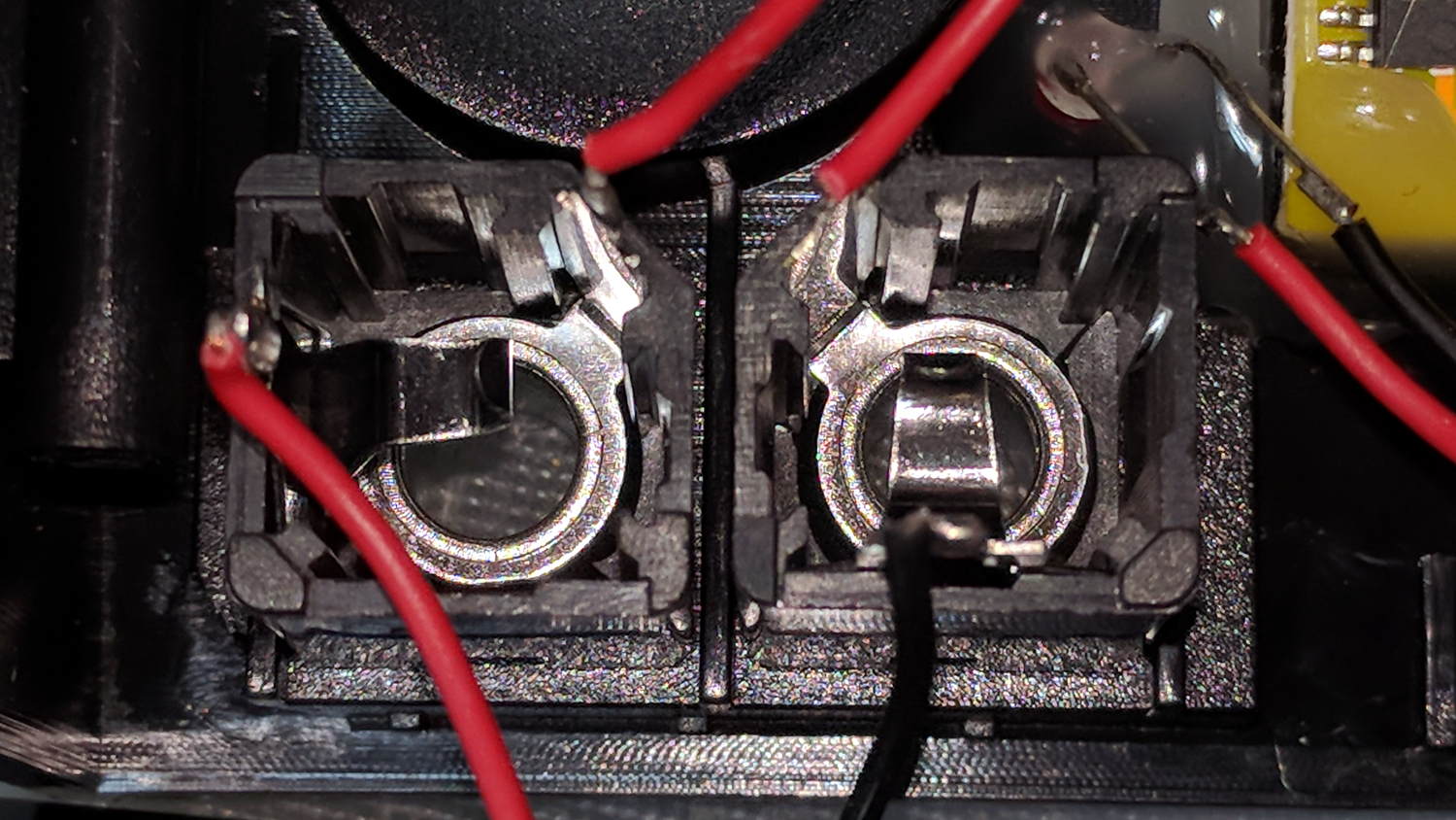
The two 1/4 inch jacks on the front panel are wired in series, so it didn’t matter which one got the tattoo needler or the foot switch:
Tattoo Digital Power Supply – jacks in series
I rewired the sockets in parallel to eliminate the need for a shorting plug, although I cannot imagine any need for two outputs.
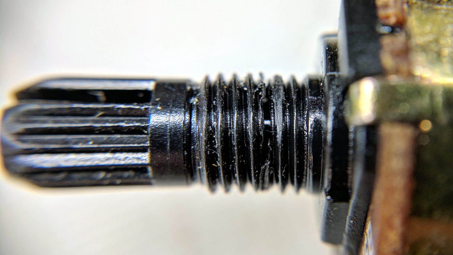
The knob seemed unusually sloppy, which turned out to be due to a broken threaded sleeve around the pot shaft that prevented the crudely made nut from seating tightly:
Tattoo Digital Power Supply – broken pot threads
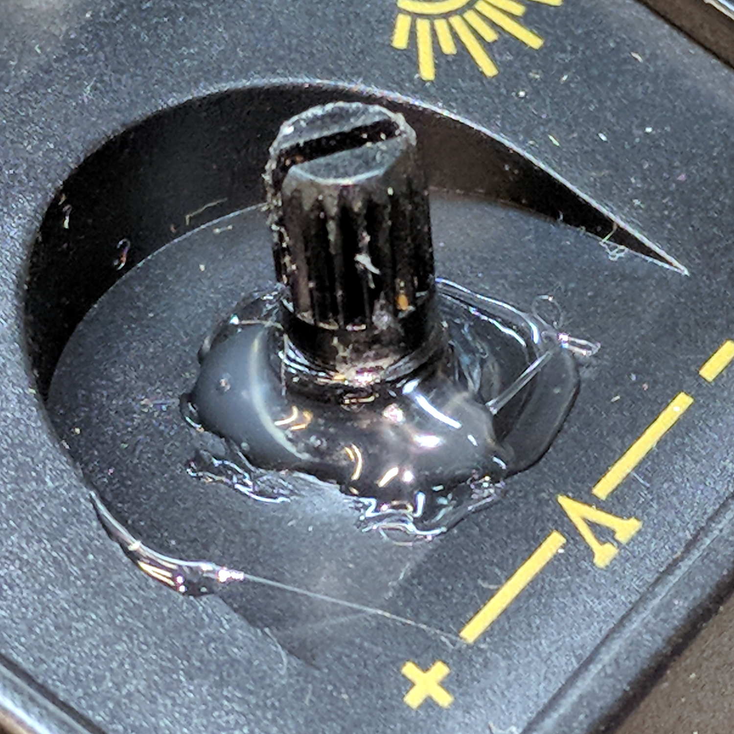
Given that the builders stuck everything else to the front panel with hot-melt glue, I followed suit:
Tattoo Digital Power Supply – glued pot threads
Which actually held it in place reasonably well, despite the hideous appearance. The knob covers the blob, so It Doesn’t Matter.
The output range extends from about 1.2 V to just over 14 V at about an amp, but the knob seems erratic and the digital meter has only a casual relationship to the actual output voltage.
I think if you regard this one as a parts kit, reverse-engineer the schematic (which surely descends directly from the RM6302 datasheet), and rebuild the electronics, it might work better.
Bottom line: The analog version seems to be better as a low-budget power supply, not least because it has a metal case and an actual power transformer for galvanic isolation.
Three times is enemy action, but we’re not there yet. I was willing to believe something I’d done had killed both of the radios, even though it seemed unlikely for them to last five years and fail almost simultaneously.
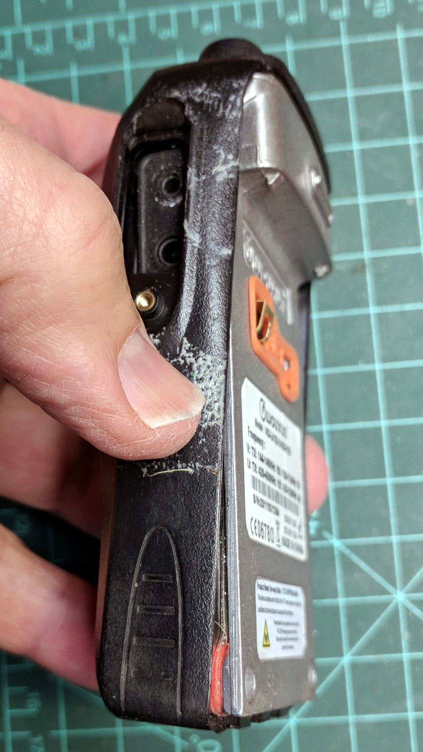
So I dismantled this one to see what’s inside. Pull off both knobs, remove the two screws at the bottom of the battery compartment, pry gently with a small screwdriver, and the whole PCB pulls out:
Wouxun KG-UV3D – disassembly
A bit more prying separates the big pieces:
Wouxun KG-UV3D – interior
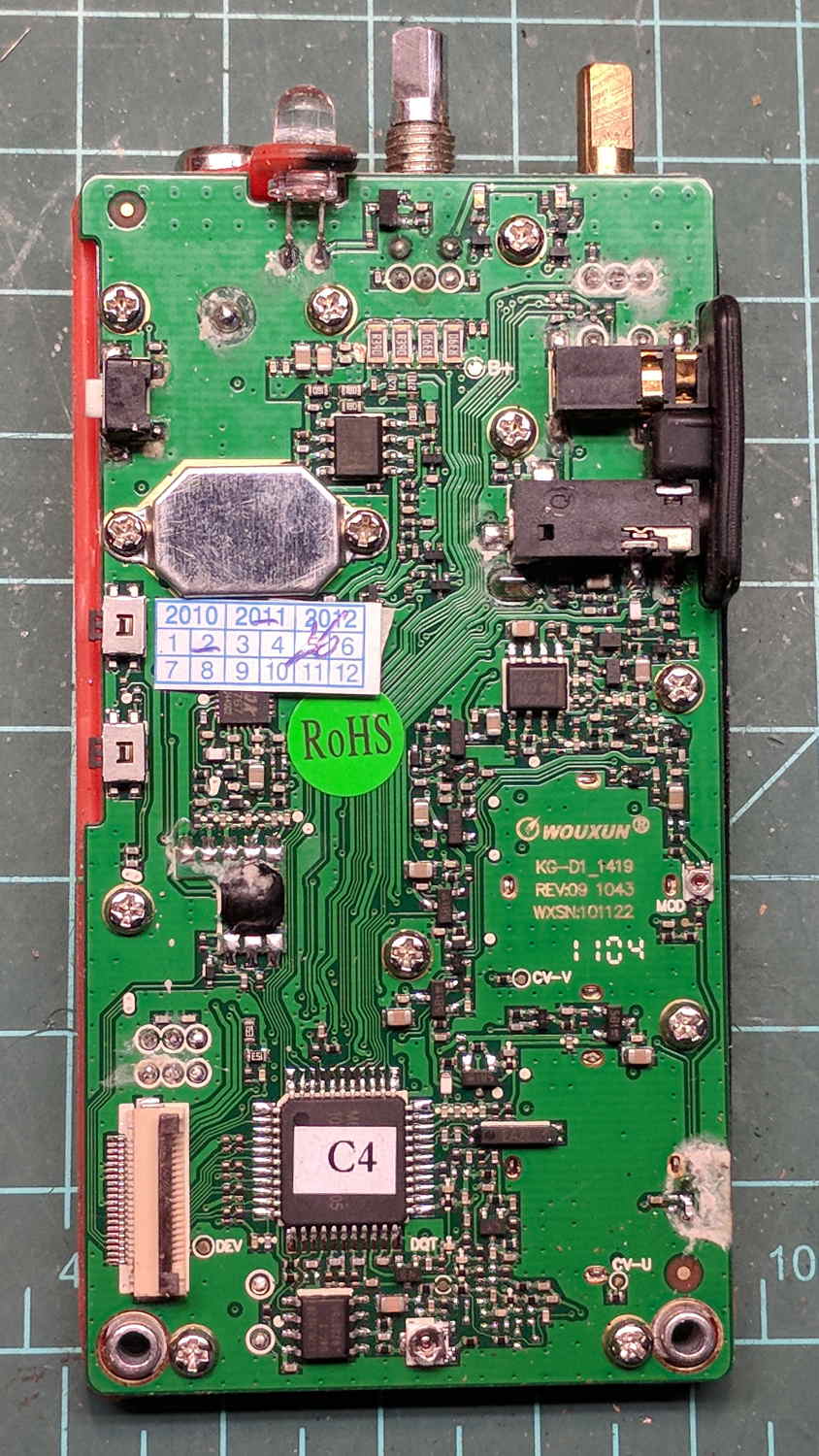
Looking closely at the main PCB showed some problems I definitely didn’t cause:
Wouxun KG-UV3D – PCB overview
Although it’s been riding around on my bike, the white blotches on the PCB came from inadequate flux removal after hand soldering.
A collection of images taken through the microscope reveals the problems:
This slideshow requires JavaScript.
I swabbed off the crud with denatured alcohol to no avail. The bottom side of the PCB has even more components and, I’m sure, even more crud, but I didn’t bother removing all the screws required to expose it, nor did I dismantle the other failed HT.
I doubt Wouxun’s QC improved over the last few years, which means the two replacement KG-UV3D radios I just bought are already on their last legs, despite my paying top dollar to the same reputable source that sold me the first pair.
We’ll be ready for new radios on new bikes by the time these fail.
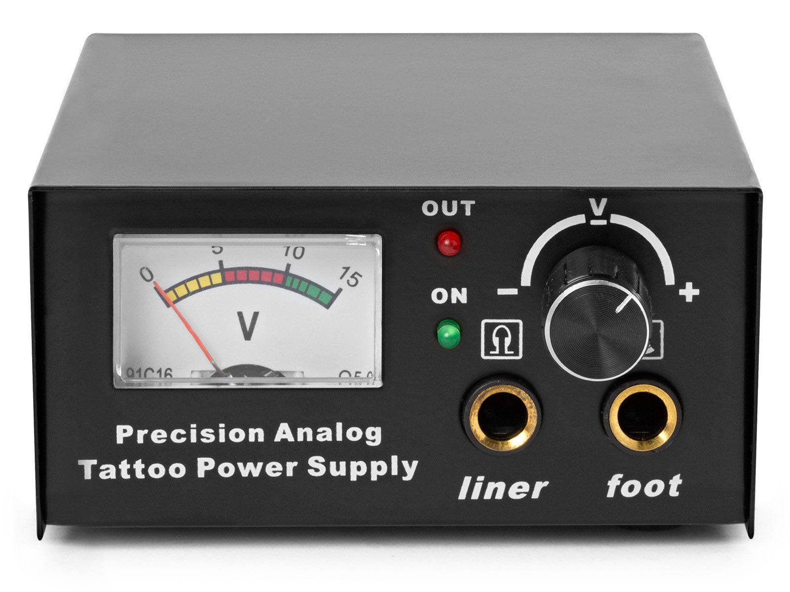
The idea behind this gadget surfaced while I was looking for something else and, although the front panel makes my skin crawl, it’s just an adjustable DC power supply:
Let’s say it has the potential to be a DC power supply, although we might quibble about the “Precision” part.
As delivered, it’s a deathtrap. Of course, it’s not UL listed and I didn’t expect it to be.
How many lethal problems do you see?
Tattoo power supply – original AC wiring
For starters, it has a three-wire AC line cord with the green-and-yellow conductor chopped off flush with the outer insulation inside the heatshrink tubing just behind the transformer:
Tattoo power supply – ungrounded AC line
The blue wire is AC neutral, but it really shouldn’t be connected to the finger-reachable outer fuse terminal.
The brown wire is AC line, which goes directly to one power switch terminal. In the event of a hot wiring fault, an unfused conductor touching the case will test the GFI you should have on your bench wiring.
The AC line cord uses some mysterious copper-colored metallic substance that’s about as stiff as music wire:
Tattoo power supply – stiff AC wire
The strands cannot be twisted together like ordinary copper wire, although they can be soldered. They may be copper-plated aluminum, because a magnet ignores them.
After soldering the strands together, they snap when bent:
Tattoo power supply – soldered broken AC wire
Generous strain relief is not just a good idea, it’s mandatory.
After some Quality Shop Time, the ground wire now connects to the case through the transformer’s rear mounting screw, the neutral AC wire connects to the transformer, the hot AC wire goes to the tip of the line fuse, and the fuse cap terminal goes to the switch:
Tattoo power supply – AC line rewiring
I relocated the white LED to the middle of the meter, where it looks a bit less weird:
Tattoo power supply – revised front panel
I have no idea what “Porket indicate” might mean. Perhaps “Precision indicator”?
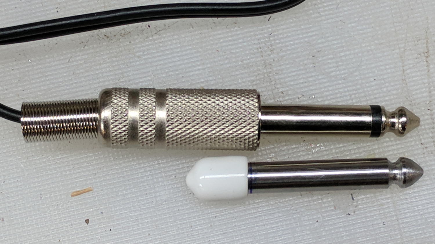
The right 1/4 inch jack, labeled “Foot”, normally goes to a foot switch you don’t need for a bench power supply, so I converted a length of drill rod into a dummy plug to short the jack contacts:
Tattoo power supply – dummy switch plug
The tip comes from a bit of lathe and file work and the white cap comes from a bag of wire shelf hardware.
A genuine hologram sticker (!) on the back panel proclaims “1.5 – 15 VDC 2 A”, which seemed optimistic. Some fiddling with power resistors suggests tattoo liners (I learned a new word!) don’t draw much current:
4 V @ 1 A
8 V @ 800 mA
10 V @ 600 mA
It can reach a bit over 18 V (pegging the meter) at lower current, so it’s Good Enough for small projects with un-fussy power requirements.