Ed Nisley's Blog: Shop notes, electronics, firmware, machinery, 3D printing, laser cuttery, and curiosities. Contents: 100% human thinking, 0% AI slop.
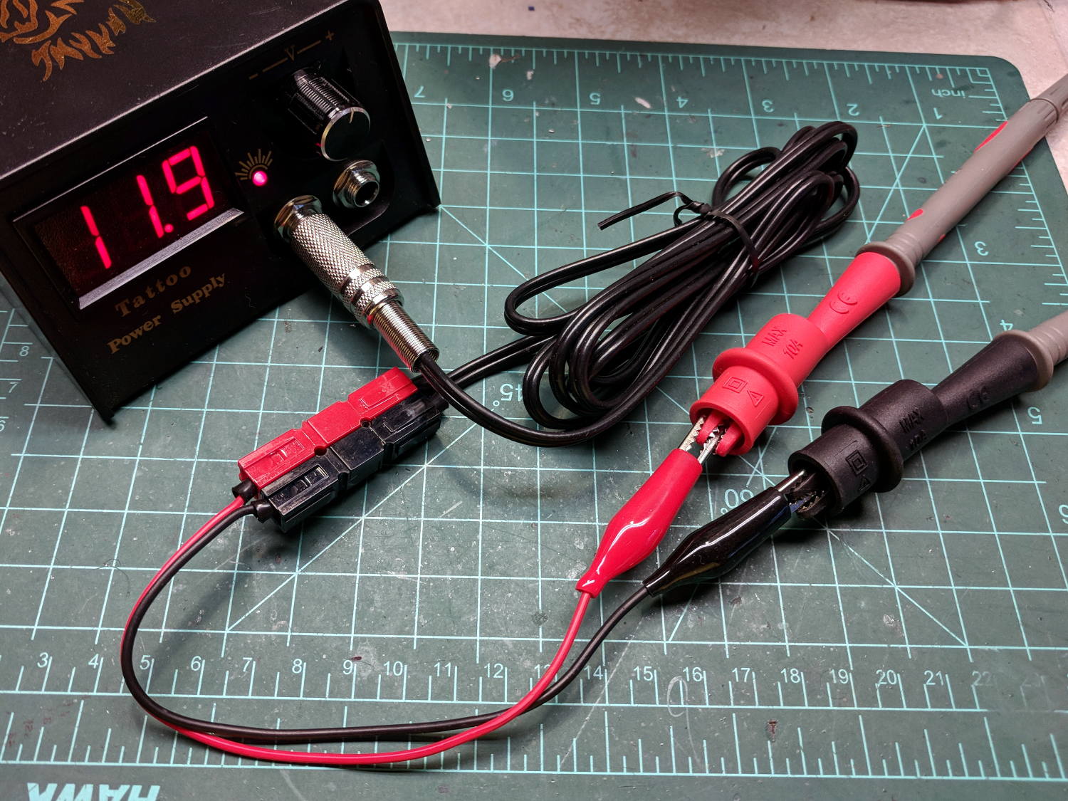
When I rewired the guts of the digital tattoo power supply to eliminate the series foot switch, I kept the original wiring polarity, with the black wire to the sleeve and the red wire to the tip:
Tattoo Digital Power Supply – internal view
It’s the same color code I (strongly) recommend in the Squidwrench Electronics Workshops: use any color for the ground / common wire as long as it’s black, then, if you have a red wire, use it for the positive supply. You can use yellow for the higher supply voltage, but stop being clever.
I put suitably colored Powerpoles on the far end of the cable to replace the standard tattoo machine spring clip connector, so I can attach clip leads, battery test fixtures, and so forth and so on.
We wired the supply into a clip-leaded diode measurement setup with a current limiting resistor and a pair of multimeters to measure the diode current and forward voltage, whereupon we noticed all the meters displayed negative voltages and currents.
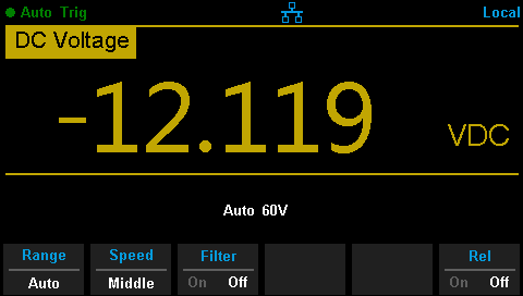
After a frenzy of wire-checking verified their setup was all good, I forced the simplest possible test, herein recreated on my bench:
Tattoo Digital Power Supply – polarity test
Which produced this display:
Tattoo Digital Supply – reverse polarity
Huh.
After a brief exploration of “Trust, but verify” territory, we swapped the clip leads from the power supply and continued the mission.
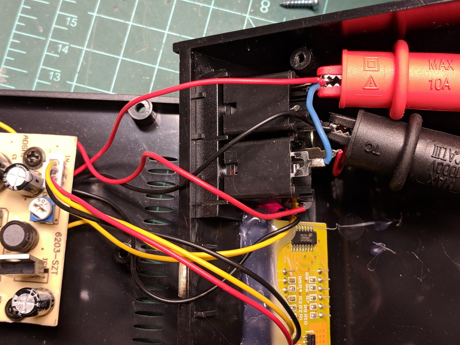
Back on my bench, I pulled the supply apart and measured the voltage at the jack terminals:
Tattoo Digital Power Supply – jack wiring
Still negative. Huh.
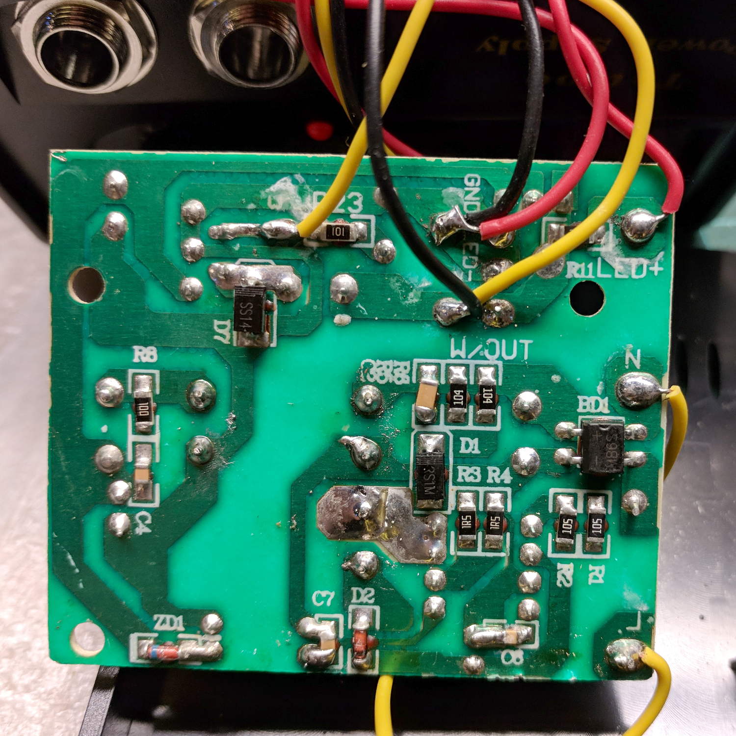
The bottom of the power supply PCB shows exactly what you should expect by now:
Tattoo Digital Power Supply – reversed color code
The red wire near the top of the board is, indeed, soldered to the trace labeled GND and goes to the jack’s tip terminal; the adjacent black wire goes to the front-panel LED. Similarly, the black wire just below it, soldered to the same trace as the yellow wire, goes to the jack’s sleeve terminal; that trace also connects to a resistor leading to the trace labeled LED+ and the LED’s red wire.
Although tattoo machines run from DC supplies, their motors or vibrators don’t depend on any particular polarity and will run fine with a backwards supply.
Resoldering the red and black wires where they should go produces the expected sign at the jack:
Tattoo Digital Supply – meter leads
Although measuring and plotting diode voltages and currents may seem tedious, actually wiring stuff together and taking data reveals how difficult the real world can be.
I trusted the supply’s internal color code and, although I’m certain I tested the Powerpoles, I obviously didn’t notice the meter’s sign.
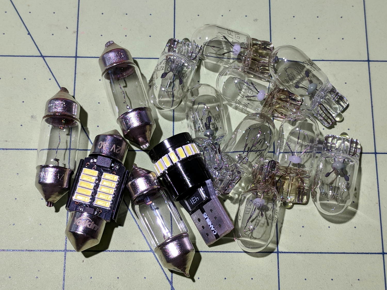
Despite what look like “squeeze here” markings, you must push the license plate bulb holders toward the center of the car:
Subaru Forester 2015 – license plate bulb holders
They were both stuck firmly to the trim plate, so I braced a screwdriver against the outboard edge of the trim panel, after which it becomes obvious how pressing inward compresses the (plastic) spring clip so you can pull the outward side of the holder away from the hatch.
The bulbs with conical ends, known as “festoon” lamps, (unsurprisingly) come in several lengths. The Forester bulbs are about 25 mm long, (unsurprisingly) much shorter than the 31 mm LEDs that seem to be the smallest available replacements, but (surprisingly) the socket tabs have barely enough compliance for the extra half dozen millimeters:
Subaru Forester 2015 – dome with 31 mm festoon LED bulb
The LEDs are much much much brighter than the incandescents, although I’d prefer warm white to cool white. The cargo compartment lamp in the back is still way too dim; I don’t understand how Subaru decided on a plastic cover tinted dark smoke gray.
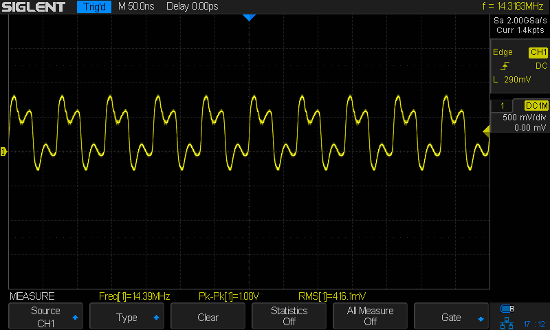
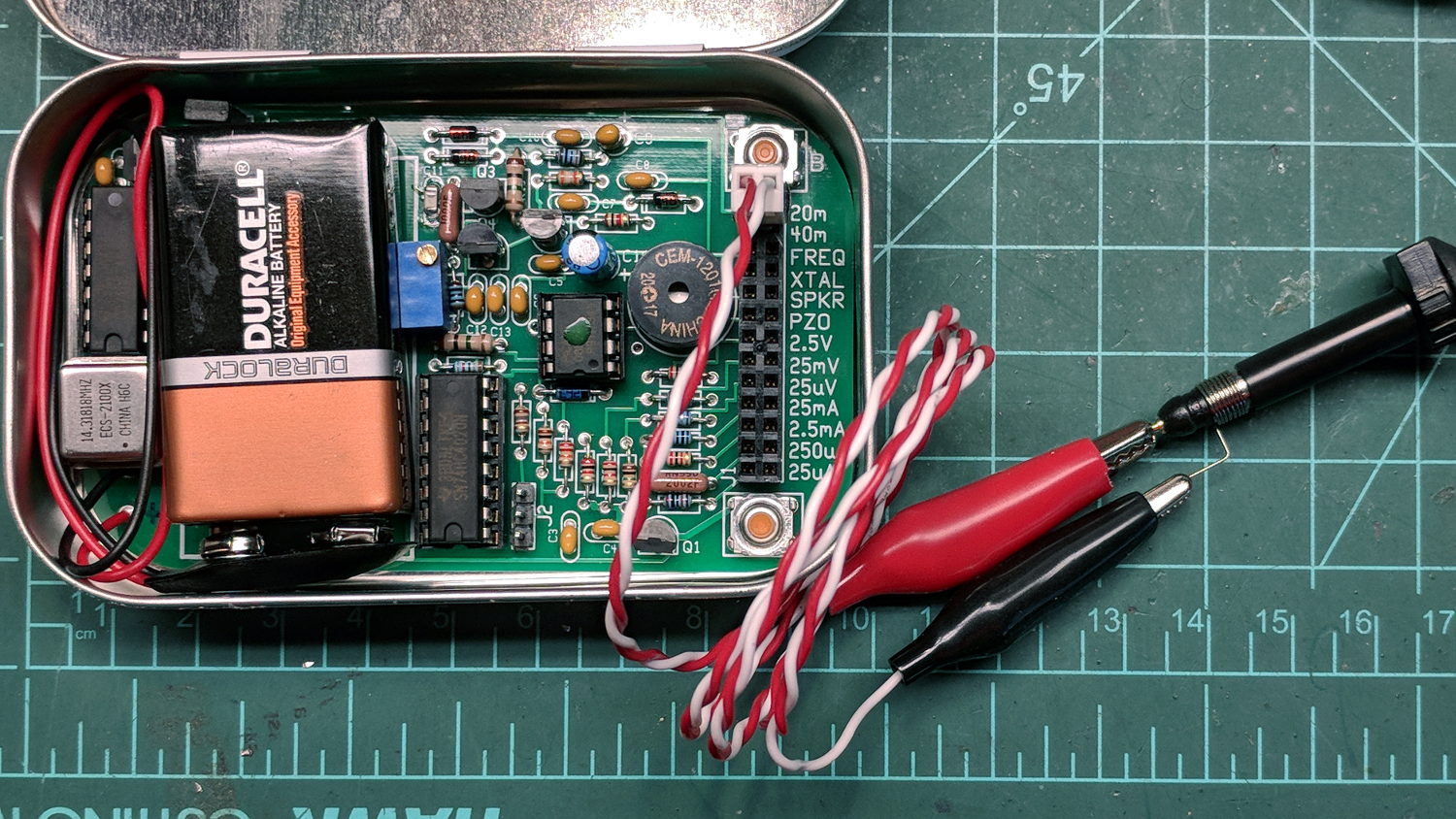
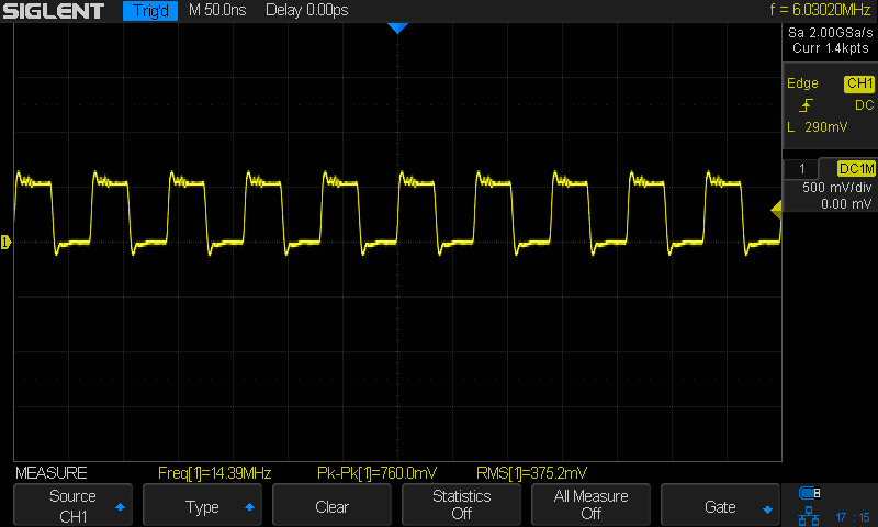
The QRPme Pocket Pal II produces RF test signals in the 20 meter and 40 meter bands, both square-ish waves derived from its 14.31818 MHz oscillator-in-a-can:
QRPme 20 meter – clip leads
That’s the 20 meter signal, seen through the twisted pair test lead with alligator clips clamped on the scope probe, thusly:
QRPme Pocket Pal II – clip leads to probe tip
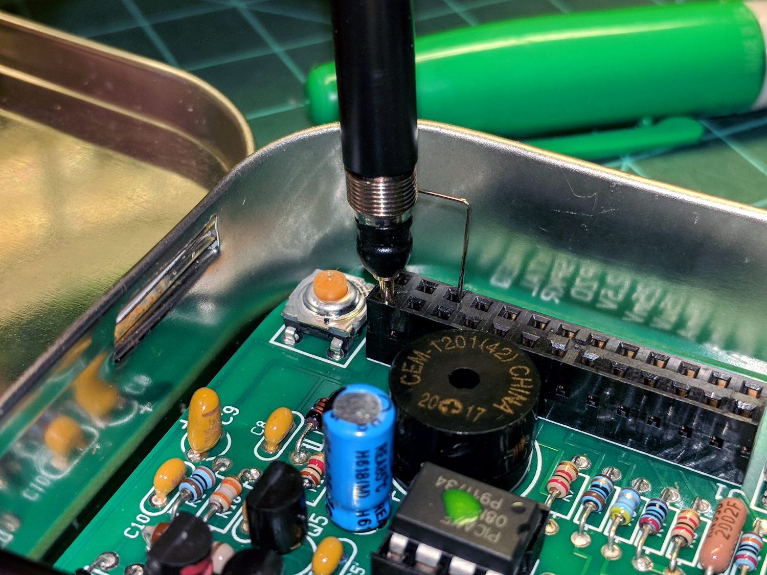
When you’re working with RF signals, the “ground” part of the probe circuit matters:
QRPme 20 meter – probe tip gnd
That’s with the probe and its short spring ground jammed directly into the header:
QRPme Pocket Pal II – probe tip gnd
Well, in this case, signal quality doesn’t matter very much, as you’re using the Pocket Pal II at a hamfest (or your bench) to determine if an HF radio is completely dead.
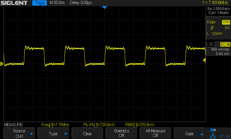
Here’s the 40 meter output, with the J3 jumper in place and the probe jammed into the header:
QRPme 40 meter – J3 on – probe tip gnd
Pulling the J3 jumper off doubles the test signal amplitude:
QRPme 40 meter – J3 off – probe tip gnd
Nothing wrong with those signals! In a pinch, those edges probably produce harmonics up in the UHF bands.
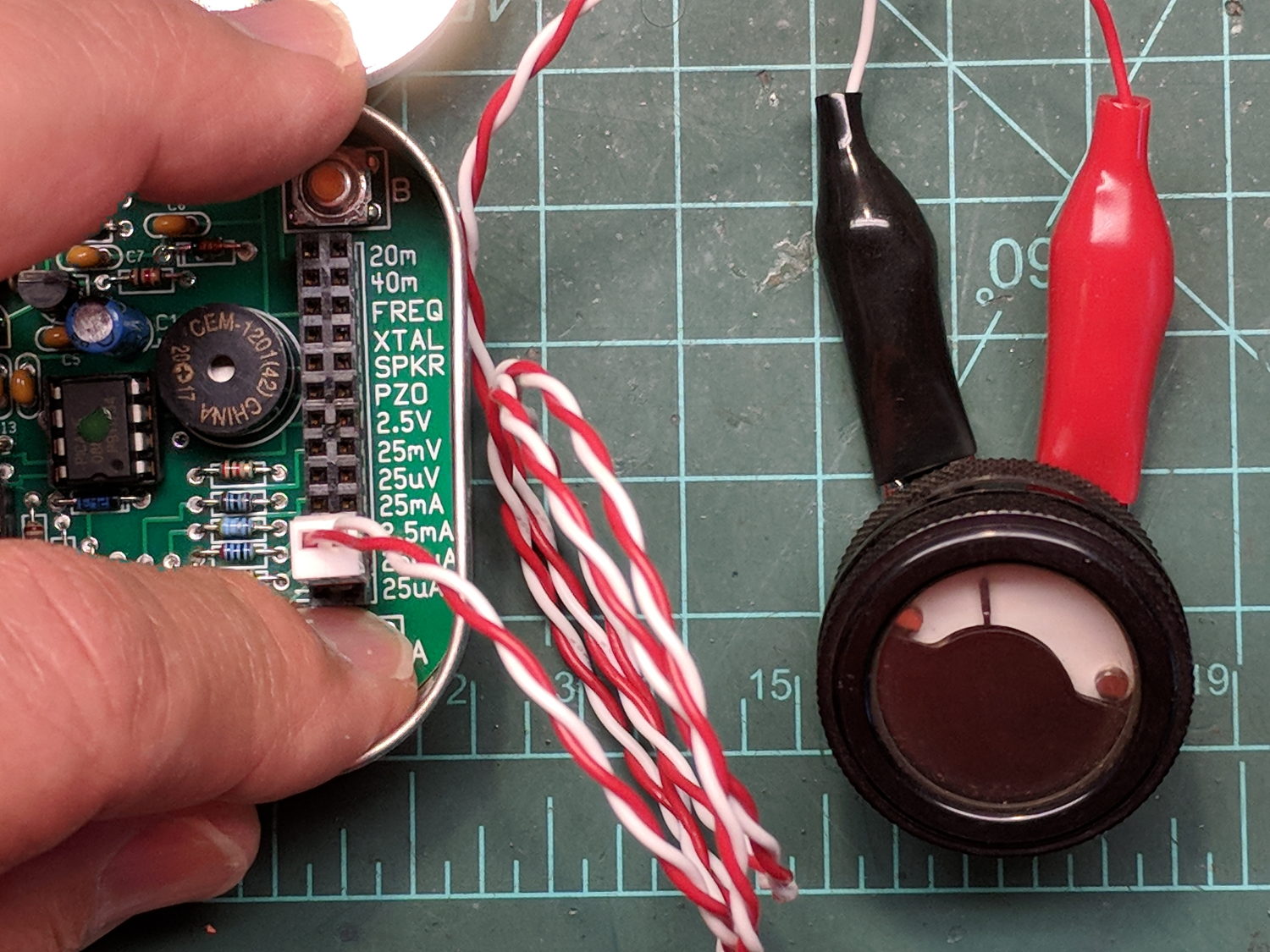
For completeness, here’s the 250 μA DC output driving a contestant chosen from the Box o’ Meters:
QRPme Pocket Pal II – 250 uA meter test
Eyeballometrically, the meter wants to see 1 mA for full-scale deflection, which is the whole point of the tester.
The heatsink (surely harvested from a PC, then salvaged from a box o’ goodies) runs about 25 °C above ambient while dropping a 12 V input to 5 V at 180 mA, so it’s good for maybe 2°C/W. It carries a KA278RA05C LDO regulator; you’d probably want something fancier in real life.
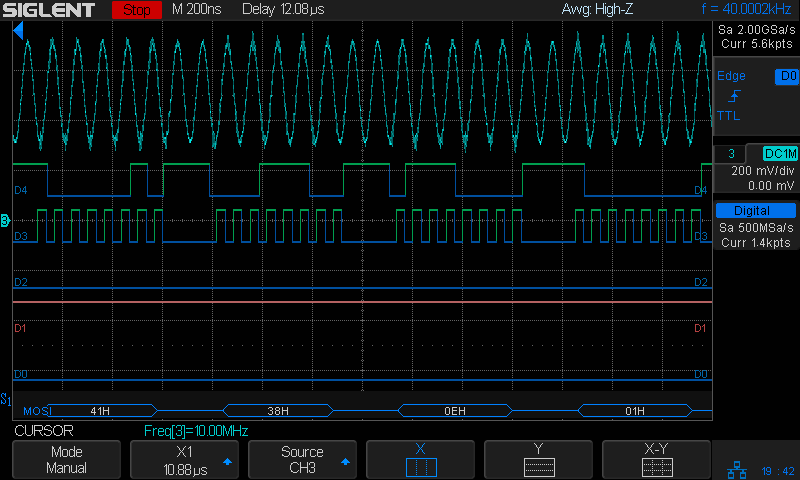
The AD9851 DDS requires a 5 V supply to run at 180 MHz from the 30 MHz oscillator on its PCB, with the side effect of putting its minimum Logic 1 Voltage threshold at 3.5 V. Because the Teensy 3.6 runs at 3.3 V from its own on-board linear regulator, the DIP 74AHCT125 level shifter between the two boosts the Teensy’s LVCMOS SPI signals to good old TTL.
The sticker on the CPU reminds me of the jumper cut between the USB +5 V line and the VIN pin, thus putting the Teensy on the better-regulated local supply for the benefit of its ADC reference:
I ran header pins along both sides of the Teensy to simplify attaching scope probes and suchlike; the dangling gray wire brings the scope’s Arbitrary Function generator signal to the Teensy’s A9 input.
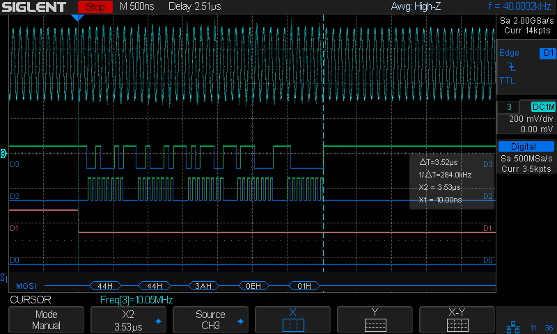
The FMDDS Mock 3 firmware lit right up, albeit with the faceplant of sending the SPI bytes in the wrong order and the wrong bit direction, which was easily fixed after a bit of puzzling:
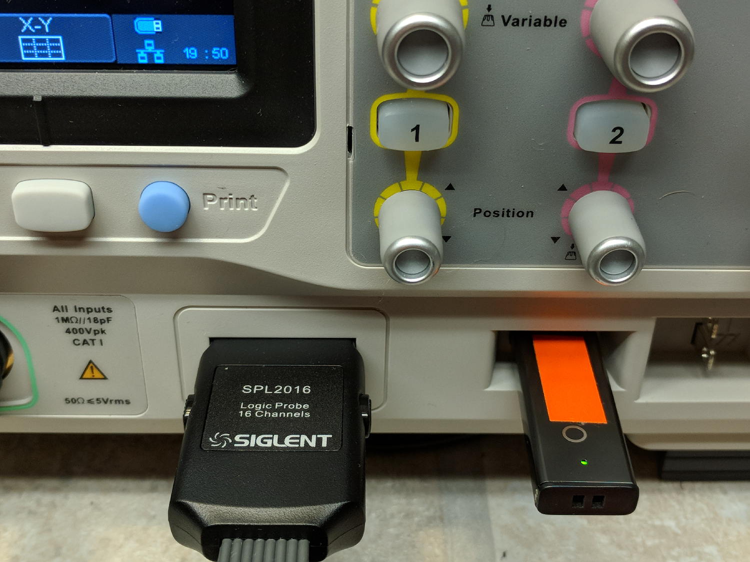
Poking the Print button on the front of the Siglent SDS2304X scope saves the screen to a BMP file (in the /BMP directory) on a USB flash drive plugged into its front-panel port:
Siglent SDS2304X Front Panel – Print Button – USB port
Which produces files like these:
ll --block-size=1 /path-to-USB-stick/BMP/
total 2318336
drwxr-xr-x 2 ed ed    4096 May 23 13:13 ./
drwxr-xr-x 4 ed ed    4096 Dec 31  1969 ../
-rw-r--r-- 1 ed ed 1152054 May 23 13:13 SDS00001.BMP
-rw-r--r-- 1 ed ed 1152054 May 23 13:13 SDS00002.BMP
The files are 1152054 bytes long, as specified by the BMP header inside the file:
hexdump -C /path-to-USB-stick/BMP/SDS00001.BMP | head
00000000  42 4d 36 94 11 00 00 00  00 00 36 00 00 00 28 00  |BM6.......6...(.|
00000010  00 00 20 03 00 00 e0 01  00 00 01 00 18 00 00 00  |.. .............|
00000020  00 00 00 94 11 00 00 00  00 00 00 00 00 00 00 00  |................|
00000030  00 00 00 00 00 00 01 01  01 01 01 01 01 01 01 01  |................|
00000040  01 01 01 01 01 01 01 01  01 01 01 01 01 01 01 01  |................|
*
00000880  01 01 01 01 01 01 01 01  01 01 01 01 01 01 1e 1e  |................|
00000890  1e 1e 1e 1e 1e 1e 1e 1e  1e 1e 1e 1e 1e 1e 1e 1e  |................|
*
00000990  1e 1e 1e 1e 1e 1e 01 01  01 01 01 01 01 01 01 01  |................|
The first 14 bytes contain the Bitmap file header, with the file size in Little-Endian order in the four bytes at offset +0x02: 0x00119436 = 1152054.
The four bytes at offset +0x0A give the offset of the pixel data: +0x36. That’s the series of 0x01 bytes in the fourth row. Unlike most images, BMP pixel arrays start at the lower left corner of the image and proceed rightward / upward to the last pixel at the upper right corner.
The data between the Bitmap file header and the start of the pixel data contains at least a Device Independent Bitmap header, identified by its length in the first four bytes at offset +0x0E. In this case, the length of 0x28 = 40 bytes makes it a Windows (no surprise) header.
The two bytes at +1C give the bits-per-pixel value: 0x18 = 24 = 3 bytes/pixel, so parse the pixels in RGB order.
The four bytes at +0x12 give the bitmap width in pixels: 0x320 = 800. Each pixel row must be a multiple of 4 bytes long, which works out fine at 2400 bytes.
The tail end of the file shows one dark pixel at the upper right:
hexdump -C /path-to-USB-stick/BMP/SDS00001.BMP | tail
00118330  00 cc 00 00 cc 00 00 cc  00 00 cc 00 00 cc 00 00  |................|
00118340  cc 00 00 cc 00 00 cc 00  00 cc 00 00 cc 00 00 cc  |................|
00118350  00 00 cc 00 00 cc 00 00  cc 0f 0f 75 1e 1e 1e 1e  |...........u....|
00118360  1e 1e 1e 1e 1e 1e 1e 1e  1e 1e 1e 1e 1e 1e 1e 1e  |................|
*
00118ad0  1e 1e 1e 01 01 01 1e 1e  1e 1e 1e 1e 1e 1e 1e 1e  |................|
00118ae0  1e 1e 1e 1e 1e 1e 1e 1e  1e 1e 1e 1e 1e 1e 1e 1e  |................|
*
00119430  1e 1e 1e 01 01 01                                 |......|
Which looks like this, expanded by a factor of eight (clicky for more dots to reveal the situation):
Screenshot – upper right corner – 8x expansion
The scope can also transfer a screenshot over the network:
lxi screenshot -a 192.168.1.42 /tmp/lxi-shot.bmp
Loaded siglent-sds screenshot plugin
Saved screenshot image to /tmp/lxi-shot.bmp
Which has the same header:
hexdump -C /tmp/lxi.bmp | head
00000000  42 4d 36 94 11 00 00 00  00 00 36 00 00 00 28 00  |BM6.......6...(.|
00000010  00 00 20 03 00 00 e0 01  00 00 01 00 18 00 00 00  |.. .............|
00000020  00 00 00 94 11 00 00 00  00 00 00 00 00 00 00 00  |................|
00000030  00 00 00 00 00 00 01 01  01 01 01 01 01 01 01 01  |................|
00000040  01 01 01 01 01 01 01 01  01 01 01 01 01 01 01 01  |................|
*
00000880  01 01 01 01 01 01 01 01  01 01 01 01 01 01 1e 1e  |................|
00000890  1e 1e 1e 1e 1e 1e 1e 1e  1e 1e 1e 1e 1e 1e 1e 1e  |................|
*
00000990  1e 1e 1e 1e 1e 1e 01 01  01 01 01 01 01 01 01 01  |................|
But the resulting file is three bytes = one pixel (!) too large:
ll --block-size=1 /tmp/lxi.bmp
-rw-rw-r-- 1 ed ed 1152057 May 23 19:09 /tmp/lxi.bmp
The tail end of the file:
hexdump -C /tmp/lxi.bmp | tail
00118330  00 cc 00 00 cc 00 00 cc  00 00 cc 00 00 cc 00 00  |................|
00118340  cc 00 00 cc 00 00 cc 00  00 cc 00 00 cc 00 00 cc  |................|
00118350  00 00 cc 00 00 cc 00 00  cc 0f 0f 75 1e 1e 1e 1e  |...........u....|
00118360  1e 1e 1e 1e 1e 1e 1e 1e  1e 1e 1e 1e 1e 1e 1e 1e  |................|
*
00118ad0  1e 1e 1e 01 01 01 1e 1e  1e 1e 1e 1e 1e 1e 1e 1e  |................|
00118ae0  1e 1e 1e 1e 1e 1e 1e 1e  1e 1e 1e 1e 1e 1e 1e 1e  |................|
*
00119430  1e 1e 1e 01 01 01 01 01  0a                       |.........|
Because the file header doesn’t include those three bytes, they don’t go into the image and the resulting screenshot is visually the same.
Which looks like a picket-fence error, doesn’t it? I’d lay long odds the erroneous loop runs from 0 to NUMPIXELS, rather than 0 to NUMPIXELS-1. Raise your hand if you’ve ever made that exact mistake.
I have no practical way to determine whether the error is inside the scope or the LXI network code, but given Siglent’s overall attention to software fit-and-finish, I suspect the former.
One can convert BMP files to the much more compact PNG format:
convert /tmp/lxi.bmp /tmp/lxi.png
convert: length and filesize do not match `/tmp/lxi.bmp' @ warning/bmp.c/ReadBMPImage/829.
Yes. Yes, there is a mismatch.
The space savings is impressive, particularly in light of PNG being a lossless format:
ll /tmp/lxi.*
-rw-rw-r-- 1 ed ed 1.1M May 23 19:09 /tmp/lxi.bmp
-rw-rw-r-- 1 ed ed  14K May 23 19:17 /tmp/lxi.png
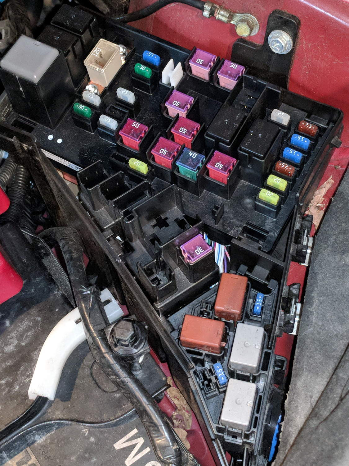
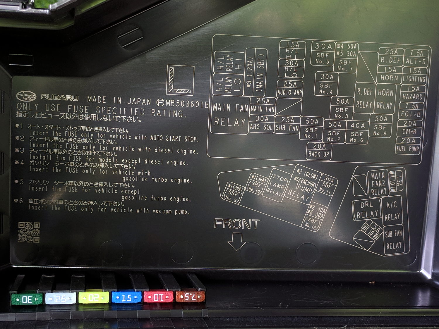
The layout chart doesn’t say what “SBF” might be (per the comment: Slow Blow Fuse), but we have a lot of whatever it is:
2015 Subaru Forester – engine compartment fuse ID
The spare fuses line up along the lower edge of the cover.
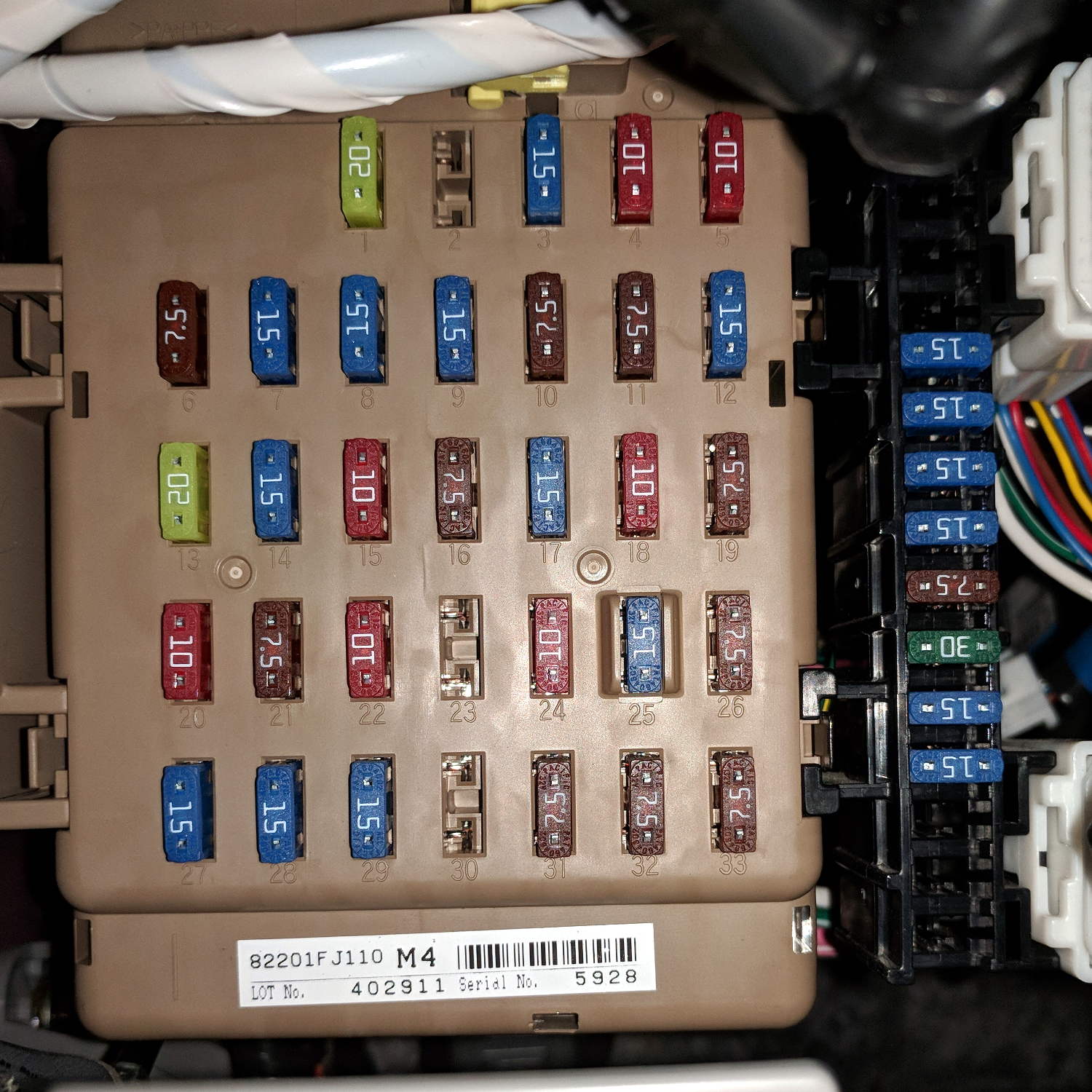
Another under the dashboard:
2015 Subaru Forester – dashboard fuse box
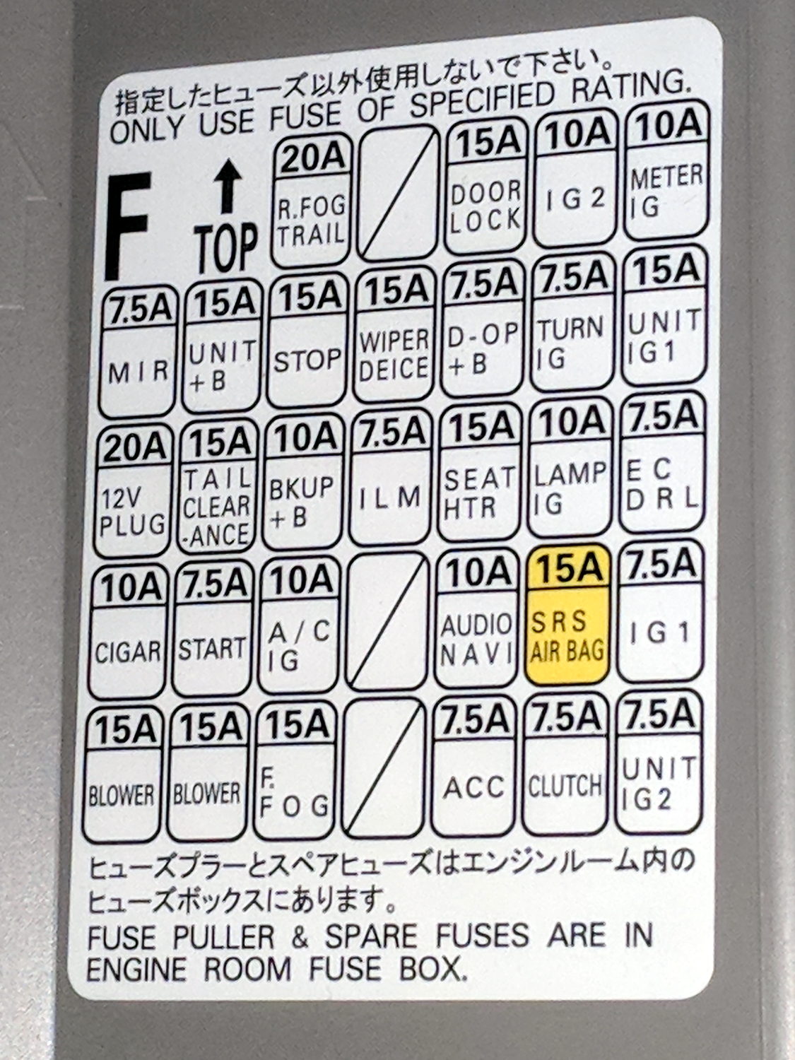
And their functions:
2015 Subaru Forester – dashboard fuse ID
The string of fuses down the right side of the main block looks like a line of spares, but they’re not. What they might be isn’t documented anywhere, which seems to be very deliberate.
Memo to Self: Having never replaced an automotive fuse, I shouldn’t start worrying now.