Ed Nisley's Blog: Shop notes, electronics, firmware, machinery, 3D printing, laser cuttery, and curiosities. Contents: 100% human thinking, 0% AI slop.
The pedal on one of Mary’s Kenmore Model 158 sewing machines lost most of its speed control abilities, which past experience has shown indicates its carbon / graphite disks have deteriorated. Fortunately, I still have a supply of disks from the Crash Test Dummy machine and have gotten pretty good at dismantling the pedal housing.
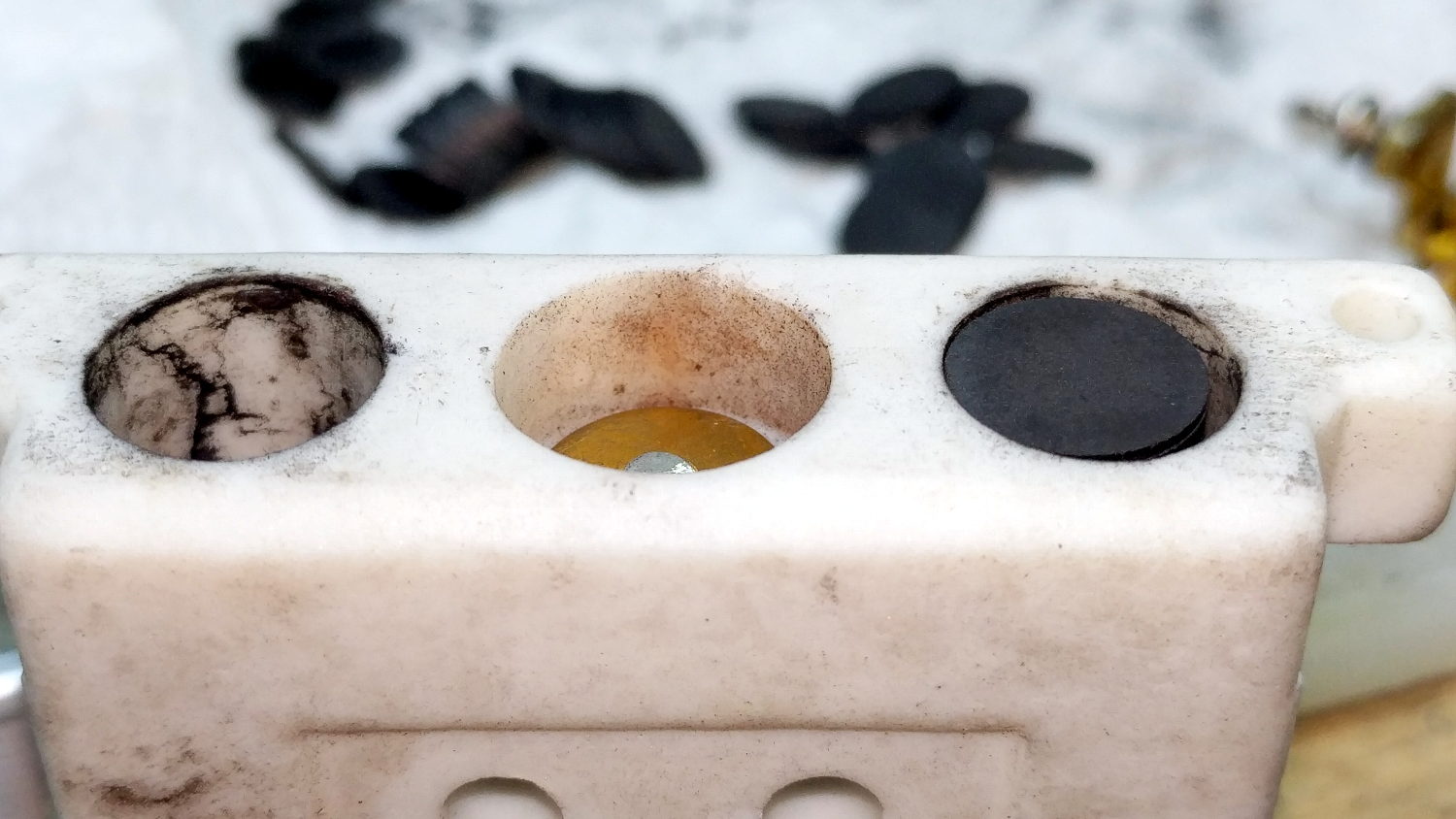
While I had the pedal apart, I filed the brass contact plates smooth again:
Kenmore 158 Pedal – graphite disk contact
Most of the deterioration happens within half a dozen disks snuggled up against those contacts, a few more on the other end of the stack against the graphite button applying the pressure, and an occasional grimy disk in the middle of the stack.
I filled both stacks flush to the top of the ceramic housing, then removed one disk from each to let the brass contacts slightly compress the stacks:
Kenmore 158 Pedal – graphite disk refill
A quick test showed the control range started a bit too fast, so I removed one more disk from the stacks, buttoned it up, and it’s all good again: a slow start with a good range.
The Description sounds enticing, in the usual eBay manner:
100% Brand new and high quality.
Product Shape: Same as the picture show
1. Product Name: High Voltage Alligator Clip Test Leads
2. Cable Type: Double-Ended Wire
3. Conductor Material& Size: 1mm²Copper Wires
4. Housing Material: Silicone
5. Max. Current: 15A
6. Withstanding Voltage: 2KV
7. Operating Temperature: -20℃~120℃
8. Making Way: Injection Molding
9. Interface Type: AC/DC
10. Color: Black, Yellow, Red, Green, Blue
Suit For:
1. Injection molding to complete, good looking, moisture proof, durable and tough!
2. Electrical test leads suitable for use with multimeters, power supplies and other electronic equipment
They’re three bucks each, which should buy you some copper and decent construction.
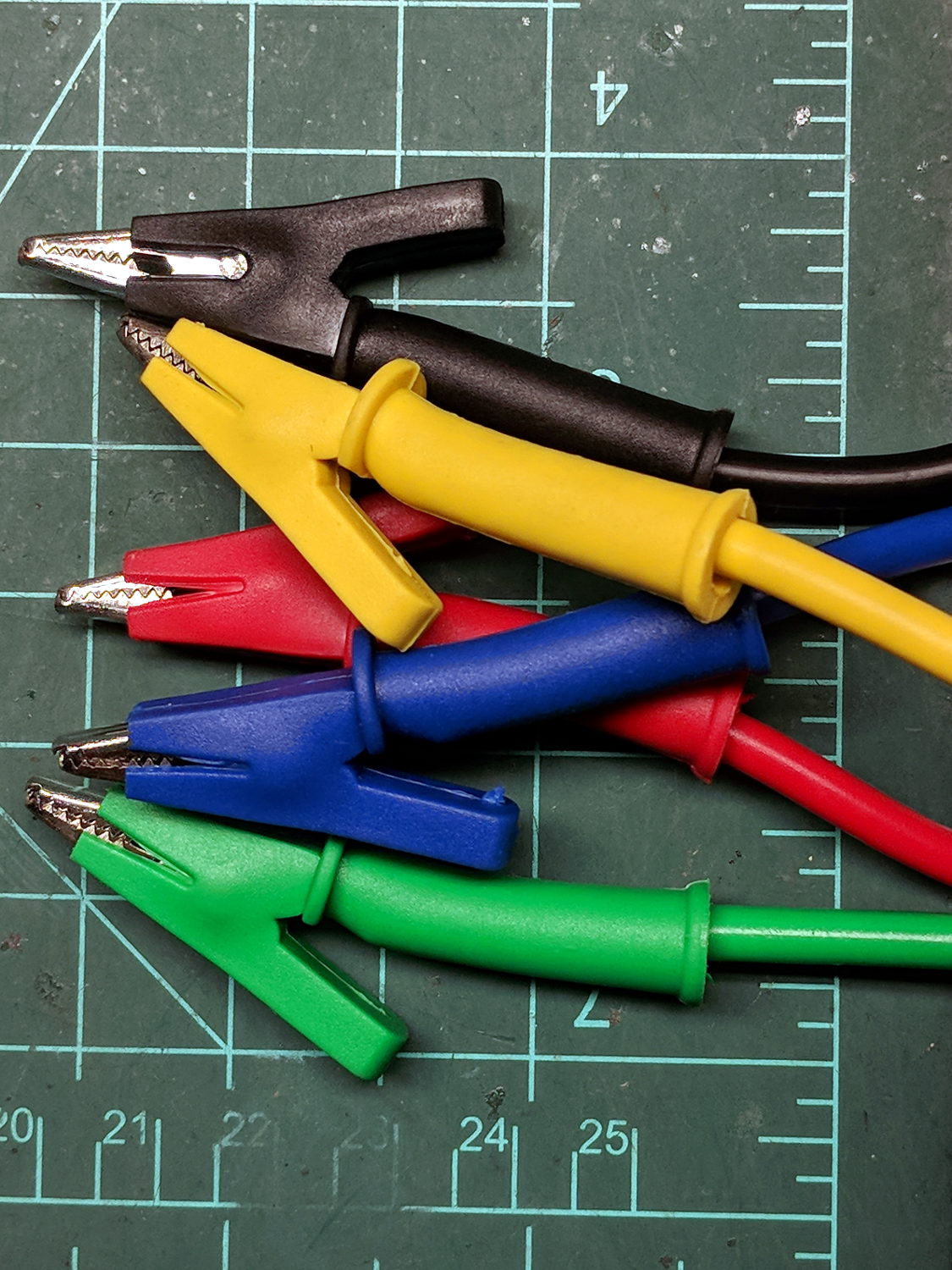
The insulation over the clips is certainly chunky enough, even if one might quibble about the standoff distance required for a 2 kV rating:
eBay HV Alligator Clips – overview
The wires have good silicone insulation and consist of fine copper strands, but I definitely won’t trust them to handle 2 kV:
eBay HV Alligator Clips – wiring
No solder, of course, just copper conductors bent back around the insulation and crimped into the alligator clip. Definitely not a gas-tight metal-to-metal joint, but good enough for simple needs.
Update: A better look at the crimp on a different clip:
eBay HV Alligator Clips – crimp
IMO, the clip’s low-strength metal can’t possibly make and hold a gas-tight joint, no matter how hard you squeeze.
There’s enough contact area for low resistance, on the order of a few tens of milliohms. We’ll see how long this lasts …
One of my Tektronix AM503 Hall Effect Current Probe Amplifiers (B075593, for future reference) lost its DC Level zero-ing capability:
Tek AM503 front panel
The front-panel knob produced only positive output voltages from maybe 50 mV to the amp’s upper limit around 200 mV (into a 50 Ω termination, Tek not being one to fool around with signal quality & bandwidth). Other than that, the amp seemed to work fine, but you definitely want a 0 V baseline corresponding to no current through the Hall probe.
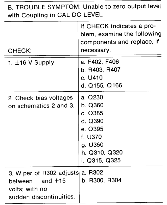
The manual includes troubleshooting recommendations:
Tek AM503 Amplifier – troubleshooting zero set problems
Because I didn’t understand the circuitry, I check the supply voltages, then started at U350, the differential amp rubbing the DC level knob against the input signal, and worked outward in both directions (clicky for more dots):
Tek AM503 Current Probe Amplifier – p 61 – Output Amplifier schematic
The PCB looks like this:
Tek AM503 – Q230 PCB detail
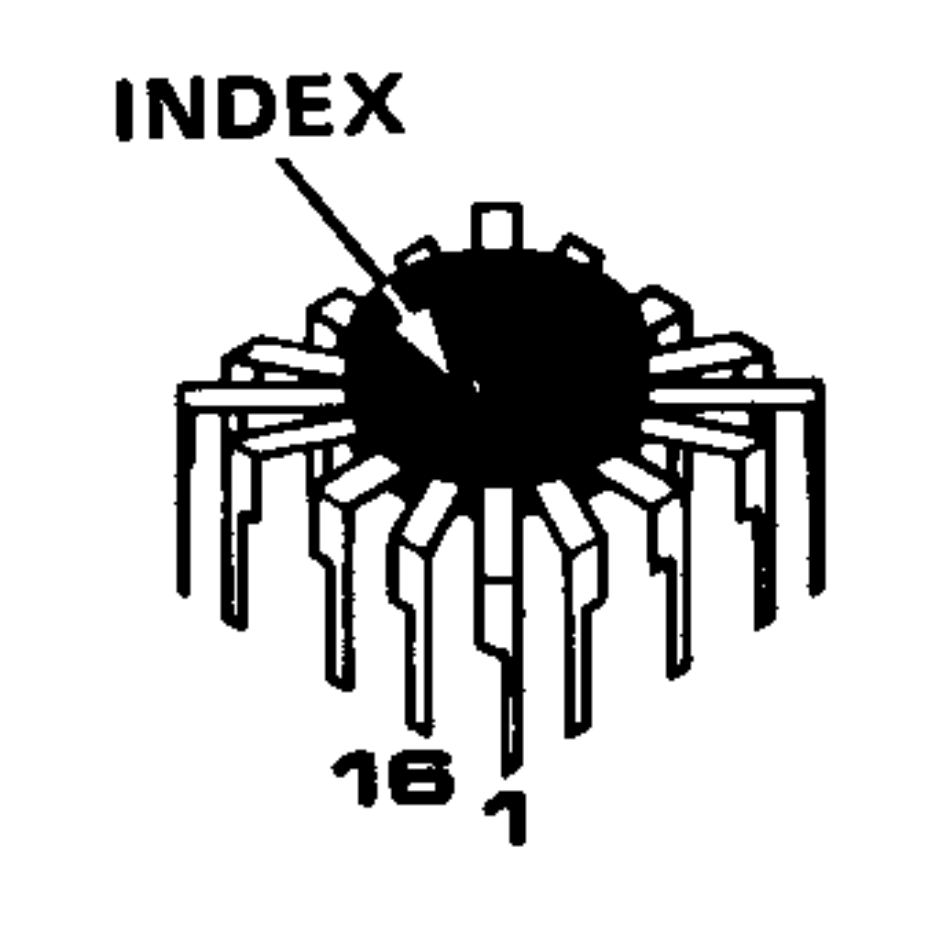
U350 is the round epoxy package in the the square spider-leg array over on the far left. Contrary to what you (well, I) might think, the index mark denotes pin 16, not pin 1:
Tek AM503 Amplifier – Tek-unique IC pinout reference
Which puts pin 1 at the upper right corner of the package on the PCB. The part listing in the manual says MICROCKT,LINEAR:VERTICAL AMPLIFIER / SELECTED, which makes perfect sense given Tek’s oscilloscope business; if you needed a high-speed differential amplifier, that’s what Tek’s internal catalog would surely suggest. Newer AM503 revisions use somewhat less unobtainable op amps, although they replace the DC Level knob with one of those newfangled microcontroller thingies for some sweet auto-leveling action.
Nothing seemed out of order. The unable-to-zero condition pushed the bias voltages off the expected values, but nothing seemed completely out of whack / stuck at the rails / broken.
The problem turned out to be in Q230, the first item on Tek’s checklist after the power supplies, even though its bias voltages looked OK. It produces the “Attenuated AC Signal” seen above and lives on another page of the schematics:
Tek AM503 Amplifier – Q230 detail
Q230 is clad in the natty red heatsink in the PCB picture above. CR226 is the metal TO-18-ish can partially hidden by the orange-red-brown ribbon cable from the DC Level pot.
For future reference, C234 and C244 aren’t installed in this PCB; they’d fit in the conspicuously vacant spots to the right and in front of Q230.
What may not be obvious at a first glance: Q230’s pins sit in teeny individual sockets installed in the PCB. One might remove and reinstall Q230, should one be so inclined and, given that it’s the first active device after the input attenuator, one might imagine such an action being necessary after a catastrophic oopsie.
At this late date, finding a suitable dual JFET would be … difficult, even were one were willing to compromise on the hermetic metal TO-78A package.
Seeing as how Q230 has been sitting quietly in its socket for the last three decades, I proceeded cautiously:
Turned the power off
Waited for the supply voltages to drop
Pulled Q230 slightly upward
Wiggled-and-jiggled it around
Shoved it back down
Turned the power on
I heroically refrained from pulling it completely out of its socket to dab DeoxIT on the pins; JFETs being notorious for susceptibility to static damage and, likely, lube would make no difference anyway.
Fired that devil up and the DC Level knob resumed doing exactly what it should:
Tek AM503 – Q230 reseated
The output now has the usual ±200 mV range centered at 0 V. The waveform shows a 100 mA signal at 50 mA/div, produced by a bench supply into a 100 Ω power resistor switched by a DC-DC SSR.
Ex post facto notes from the fourth Squidwrench Electronics Workshop.
We finally talk about (bipolar, NPN) transistors as current-controlled current sources / sinks, ruthlessly restricted to DC operating conditions.
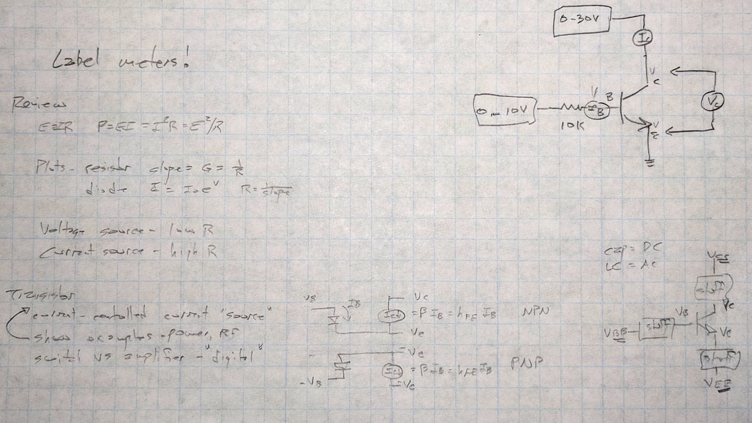
Scribbled notes of things to cover, contrast-stretched to be slightly more readable:
Session 4 – plan reminder
A bag o’ samples:
Session 4 – transistor samples
Nomenclature, regret expressed as to conventional vs electron current flow, schematic pictures vs. reality, why different packages. All six possible pinouts loose in the wild: always check datasheet and confirm device pin polarity.
Not all TO-92 packages contain transistors: voltage regulators, references, AM receivers, dual diodes, you name it, you’ll find it. When you order a million of something, you can get whatever you want.
The Squidwrench junk box parts drawers contain some genuine Mil-Spec 2N2222 transistors in genuine TO-18 metal cans, packed in individual containers labeled with their warranty expiration date. They still make ’em like that, just not for the likes of mere mortals such as I.
Reading data sheets and tamping down optimism: (large print) max voltage and max current ratings always limited by (small print) max power dissipation. Safe Operating Area bounded by datasheet limits, power becomes graceful curve on linear scales = straight line on log-log scales. Handwaving description of secondary breakdown issues, story about killing those ET227 bricks.
DC current gain β = hFE, font flourish catastrophes, uppercase subscripts = DC vs. lowercase = AC, temperature dependence, process dependence, expected spread = don’t count on any particular values.
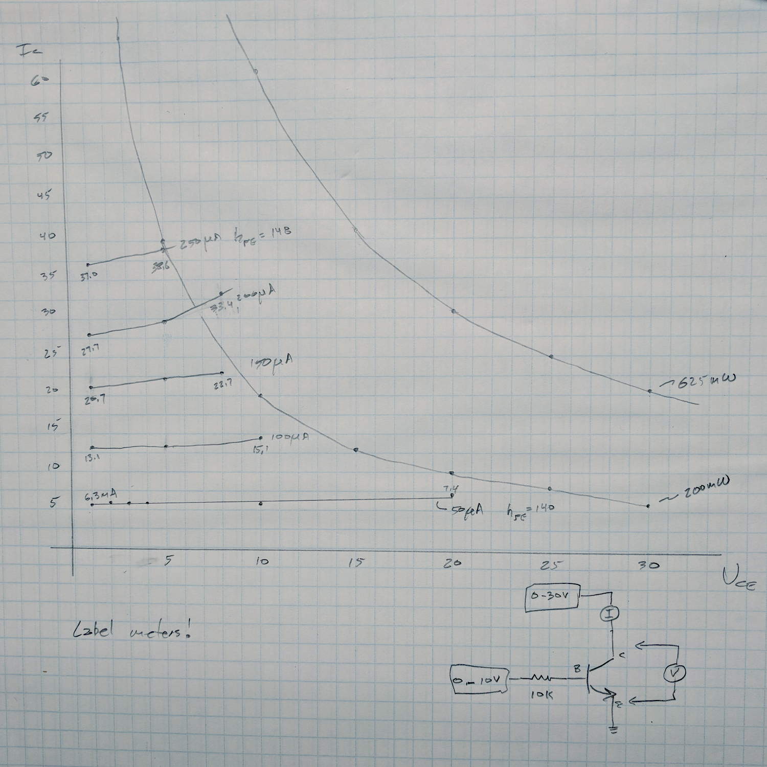
Just to show what the results should look like, I measured an MPS3704 by hand before class:
MPS3704 transistor I vs V plots
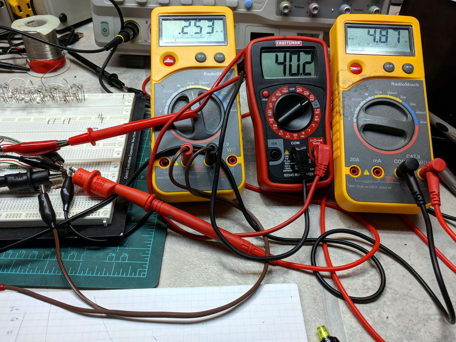
Which required two power supplies and three meters:
Session 4 – transistor measurement meters
Which, in turn, prompted me to festoon the class meters with conspicuous masking tape labels!
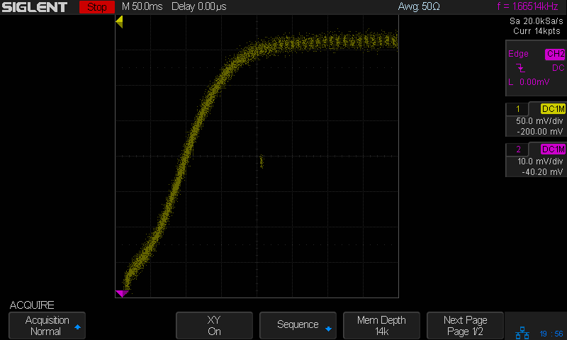
Seen a bit closer to the origin, with a fixed 100 μA base current and the scope’s arbitrary function generator producing a voltage ramp:
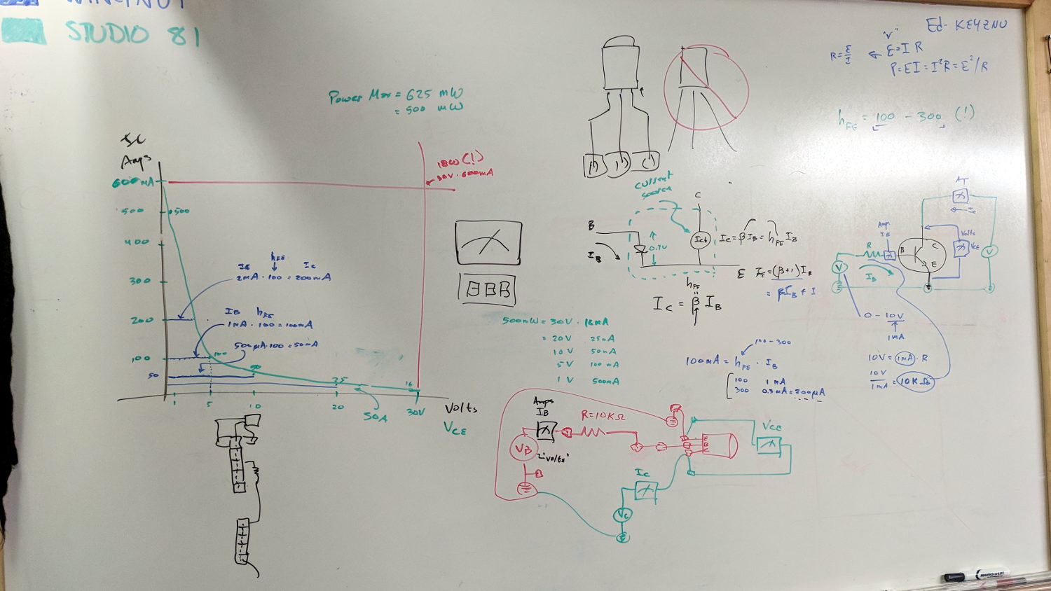
The whiteboard of introductory scribbles, with a plot of expected results:
Whiteboard – Session 4 – transistor I vs V plot
Small values of collector voltage to remain within allowable power dissipation! Discussion of switching behavior: high current at low voltage, low current at high voltage, avoid crossing the non-SOA (pulse vs DC) expanse, another mention of secondary breakdown.
After painstakingly measuring another MPS3704, compute actual current gain(s) and power dissipation:
Whiteboard – Session 4 – transistor measurements
With data in hand, we carefully increased the collector voltage with constant base current, ventured slowly into the non-SOA, and eventually measured the same base current producing no collector current at all. No smoke, much to the disappointment of all parties.
The benefit of actually measuring a (sacrificial) transistor cannot be overstated. Lots of baling-wire setup, plenty of mistakes and fumbles, hard lessons in how difficult it is to get useful numbers.
A good time was had by all, despite the absence of non-SOA smoke …
Baofeng UV-5 radios can (mostly) eliminate the loud hiss heard at the end of a transmission before the squelch kicks in after the received carrier drops: Menu → 34 STE → ON. A detailed description of the option suggests it’s a 55 Hz subaudible tone sent for 250 milliseconds after the sender releases the PTT and before the transmitter stops sending, with the receiver muting its audio during the tone. Obviously, this requires a Baofend radio at each end of the conversation, which applies to our bikes.
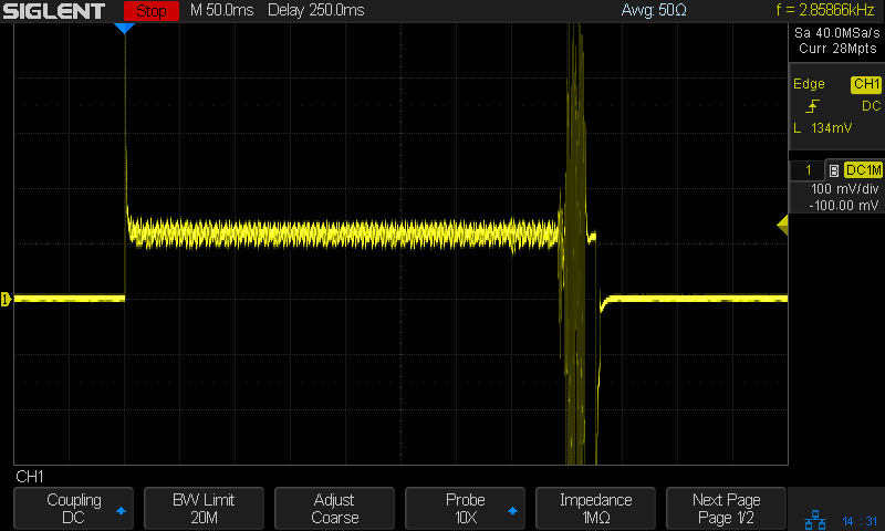
Saying “laaaa” while kerchunking (into a smaller dummy load than the hulk) with STE OFF:
Baofeng – STE OFF – laaaa
Compared to the received audio, the squelch tail hiss is really really loud.
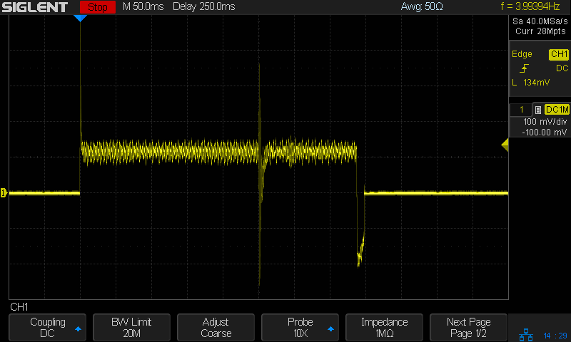
Then with STE ON:
Baofeng – STE ON – laaaa
You can see the STE tone reception start about 250 ms before the audio cuts off, although it’s not at all clear the audio is muted on either end. In any event, there’s no squelch tail worth mentioning, even if there’s an audible tick when the STE tone starts.
Saying nothing with STE ON:
Baofeng – STE ON – silent
It’s unlikely the audio output would include the subaudible tone, but you might convince yourself something happens in the 250 ms between the STE blip near midscreen and the final pop (now clipped) as the audio drops.
Perhaps because we’re using better quality earbuds, the Baofeng UV-5 radios on our bikes produce extremely loud audio, even with the volume knob just above its power-on click. Reducing the volume requires a series resistor downstream of the diodes clipping the pops:
Because we have different earbuds and different hearing, my radio has a 140 Ω resistor and Mary’s has a 430 Ω resistor. Getting the right value requires a few iterations of on-road testing, but it’s not particularly critical; the volume knob should end up roughly in the middle of its range.
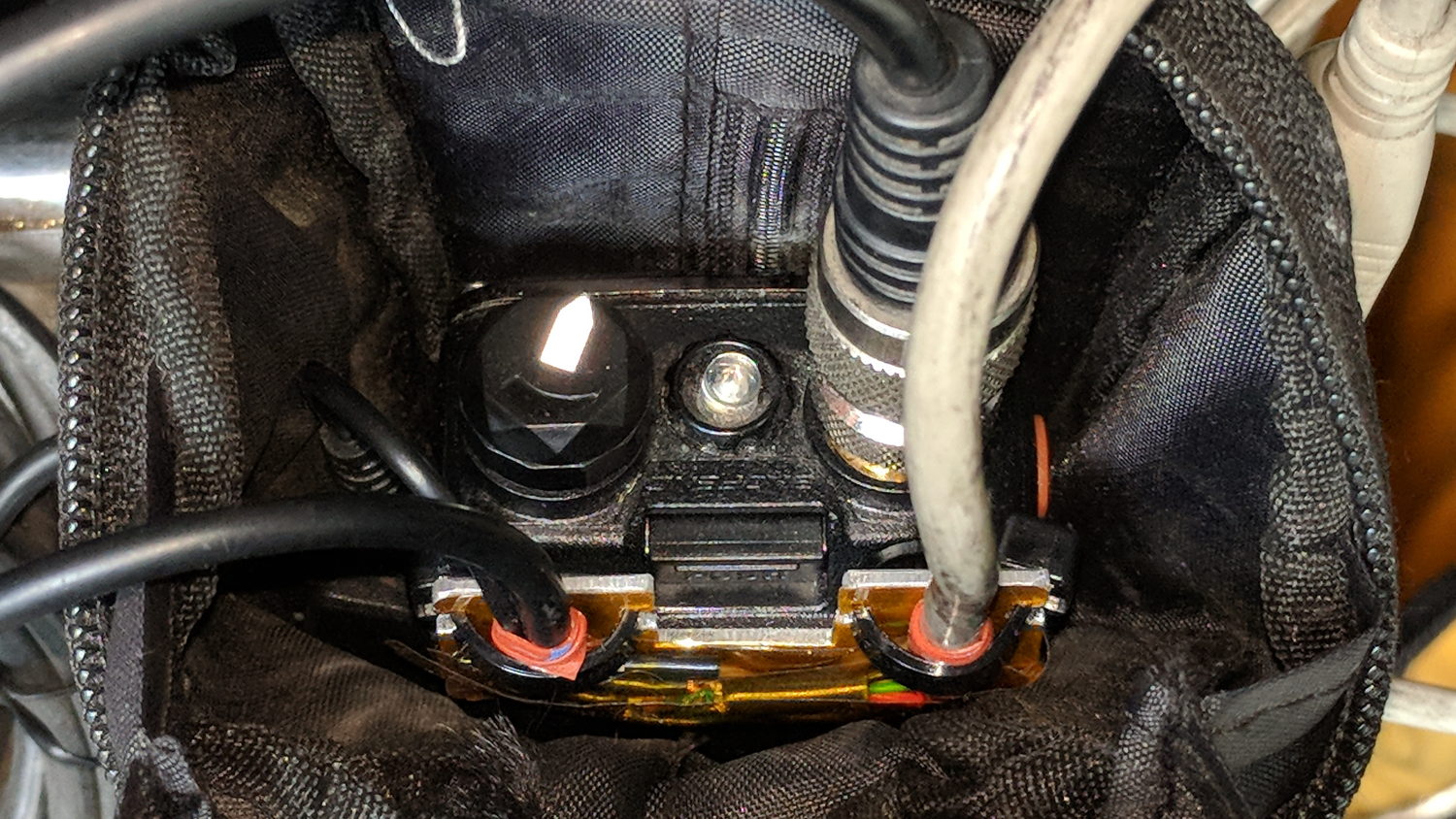
For now, all the “circuitry” lives among layers of Kapton tape:
Baofeng headset wire plate – detail
Speaking of volume knobs, Baofeng radios have large flat-top cylindrical knobs (unlike Wouxun’s fluted knobs), so I added a pointed snippet of reflective tape to make the position visible:
Baofeng volume knob – reflective pointer
The flash lights it up, but there’s enough backlighting behind your (well, my) head to make it easily visible under normal conditions. Once you figure out the proper volume, it’s easy to set the pointer in that direction before every ride.
Our first ride with the Baofeng UV-5 radios subjected us to loud pops around each transmission. Back on the bench, this is the signal applied to the earbud during a no-audio simplex kerchunk:
Baofeng – squelch pops
The small noise burst to the right of the center, just before the downward pulse, happens after the carrier drops and before the squelch closes; it’s familiar to all HT users.
The huge pulses, upward at the start and downward at the end, cause the pops. They’re nearly 3 V tall, compared with the 300-ish mV squelch noise, and absolutely deafening through an earbud jammed in my ear. Mary refused to listen, so we finished the first ride in companionable silence.
I think the radio switches the audio amp power supply on and off to reduce battery drain. It’s obviously a single-supply design, so we’re looking at a hefty DC blocking capacitor charging and discharging through the earbud resistance. I suppose that’s to be expected in a $25 radio.
The obvious solution: clamp the audio signal to something reasonable, perhaps with a pair of nose-to-tail Schottky diodes across the earbud. Rather than using axial diodes, along the lines of the 1N5819 diodes in the WWVB preamp, I used a BAT54S dual SMD diode as a tiny clamp:
BAT54S dual-Shottky diode – SMD package
No pix of the final result, but it’s basically two wires soldered alongside the SMD package, surrounded by a snippet of heatstink tubing to stabilize the wires and protect the SMD leads. It might actually survive for a while, even without the obligatory epoxy blob.
The BAT54S clamps the pops to 200-ish mV, as you’d expect:
Baofeng – squelch pops – clamped – 500mV-div
That’s a kerchunk at twice the vertical scale. The very thin spike at the start of each pop isn’t audible, as nearly as we can tell, and I’ve cranked up the audio gain to make the squelch noise more prominent. Your ears will determine your knob setting.
With the audio amp applying 3 V to the diodes at the start of each pop, you’re looking at an absurdly high pulse current. I’m sure the radio exceeds the BAT54 datasheet’s 600 mA surge current limit by a considerable margin, but I’m hoping the short duration compensates for some serious silicon abuse.
Tamping those pops down made the radios listenable.
I’ve often observed that Baofeng radios are the worst HTs you’d be willing to use.