Ed Nisley's Blog: Shop notes, electronics, firmware, machinery, 3D printing, laser cuttery, and curiosities. Contents: 100% human thinking, 0% AI slop.
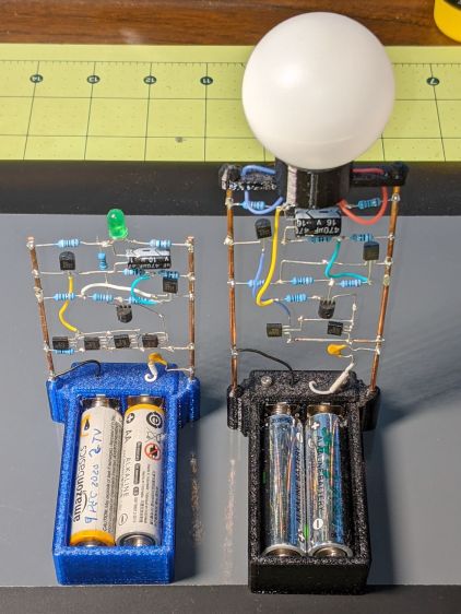
These two discrete LM3909 circuits recently stopped blinking:
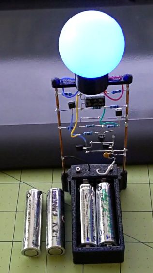
LM3909 AA alkaline – Green and Blue
The green LED (on the left) took six months to wear its pair of not-dead-yet AA alkalines from 2.7 V down to nearly zero.
The blue LED in the radome took two months to go from 1.0 V (!) to nearly zero. It didn’t start very bright and went decidedly dim along the way, but the LM3909 circuitry still managed to jam a few microamps through the LED.
In both cases, one of the cells was reverse-charged by a few hundred millivolts, although neither leaked.
Both got another set of not-quite-dead AA cells and they’re back in action.
My friend rides about the same way we do, except from a much higher perch, so I’ll start her off with a configuration similar to the one we settled on for Mary’s Tour Easy.
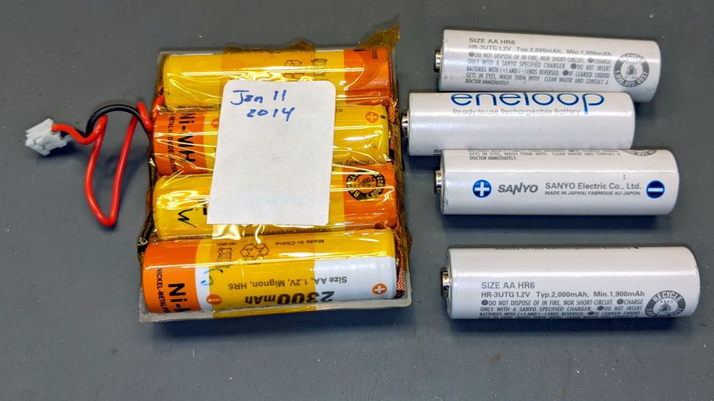
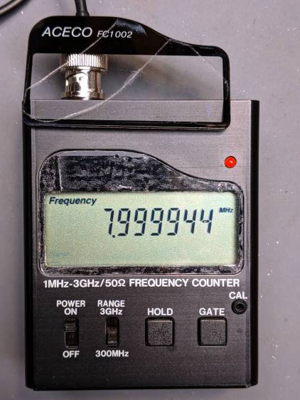
My old Aceco FC1002 frequency meter stopped working without being plugged into the charger. It runs from a quartet of NiMH cells taped into a tray I made seven years ago:
The faceplate bears the scars of its cracked acrylic (?) coating, so I pushed it out, traced the outline on a flat piece of polypropylene clamshell packaging, cut it out, and stuck it in place with tapeless sticky:
Aceco FC1002 – polypropylene faceplate
That removes the branding, but IMO improves the appearance.
It should continue working for another half decade or so!
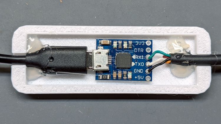
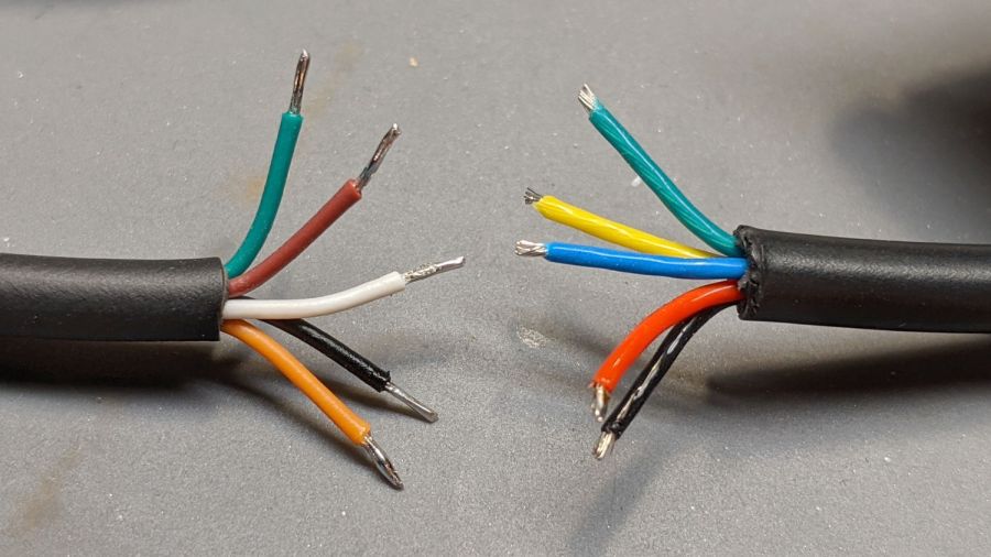
The new cable on the left seemed like it might match the canonical colors:
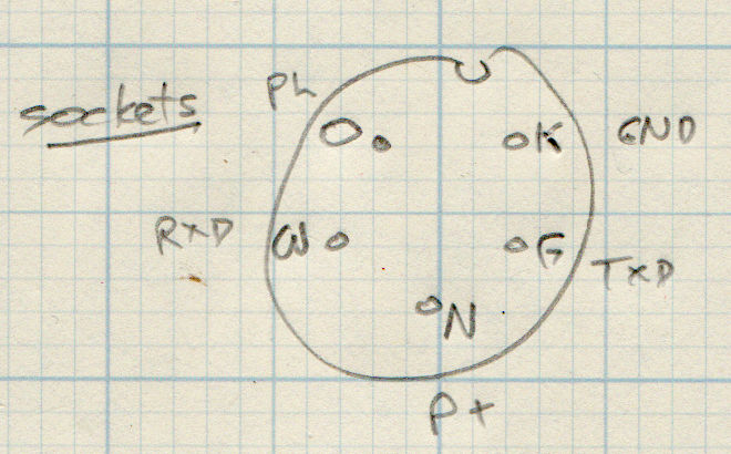
Bafang BBS02 display cable pinout
It comes heartbreakingly close:
Bafang Display Cable – extension colors
Brown and Orange connect as the naive user might expect, which does reduce the likelihood of incinerating the motor controller / USB adapter / laptop by connecting the 48 V battery directly to the logic-level electronics.
However, White wasn’t on the original menu, Green is now TXD, and Black has become, comfortingly, GND.
Verily, it is written: Hell hath no fury like that of an unjustified assumption.
This socket connector has a watertight shell making it extremely difficult to mate and unmate with the pin connector on the bike. Watertightness being unnecessary, a little razor-knife action seems in order:
Bafang Display Extension Cable – shroud trimming
Visually, they’re both green-ish, but sometimes the Pixel camera accentuates any differences.
So these brief notes, compiled before I read the Okendo TOS, should serve the same purpose as an actual review, minus the nonsense of providing even more of my sensitive bits.
Bose discontinued their Hearphones last year. While I’m reasonably happy with how mine work, they seem to last about a year before something fails. Bose replaced the first unit after its covering delaminated, replaced the second unit when a wire failed in the left microphone, and the third unit is now approaching one year of steady use.
The Hearphone necklace curled around the IQbuds charging case:
Bose Hearphones – Nuheara IQbuds2 MAX
Comparing the IQBuds² MAX to the Bose Hearphones:
Heavier in the ears, but without the necklace
Poor battery runtime, both have non-replaceable batteries
Poor ear seal with silicone tips, OK with Nuheara’s foam tips
Immediate access to “World off” mode!
“World off” mode seems noisier, even with ANC on
Better dynamic noise control / filtering
The tradeoff for not having the Bose necklace is, of course, carrying a smaller battery in each ear. Everybody’s claimed run times are optimistic, but after a year the Hearphones still last the better part of a day, while new IQbuds generate range anxiety after a morning and must then spend a while recharging in their case.
The stock IQbud silicone tips exert entirely too much pressure on my ear canals. The foam tips produce a much better seal and were easier to wear for more than a few hours. The Bose “Stayhear” shaped silicone tips fit much better and suppress external sound just as well as the IQbud foam tips.
Replacing the stock IQbuds foam tips (described as “Comply memory foam”) with actual Comply memory foam tips directly from Comply was a definite step up that should not be necessary; they are similar, but visibly different. According to Comply’s online fit selector, you need their Isolation T-167 Sennheiser-specific tips, even though Nuheara hardware appears in Comply’s selector.
The IQbuds tap controls, except for the simplest single tap, barely work. I cannot perform a double-tap, because the bud registers the first tap as a single tap and either discards the second tap or registers it as another single tap. Long taps generally work, except when they don’t, having nothing to do with tap duration or force. Tech support tells me the buds use the audio signal to determine when a finger taps the bud, but AFAICT tap sensitivity is much too high and the discrimination entirely too unfussy.
Amusingly, nibbling dark chocolate can produce exactly the correct audio signal to trigger the “World off” tap in the right bud and, occasionally, the “Play / Pause” tap in the left bud. I rest my case.
For someone requiring far more audio gain than a typical hipster, firmly tapping an ear bud is an … uncomfortable … user interface.
Fortunately, a single correctly executed tap on the right bud mutes the microphones and turns on Active Noise Cancellation; the Hearphones bury that vital function on a tiny icon inside the Bose app, requiring many seconds to start and activate.
The IQbuds app (and, presumably, the bud firmware) does not allow assigning any tap function to any bud + tap pattern. For example, there’s no way to access both “change location” and “change focus” by tapping, because both those functions can be activated only by the right bud’s long tap: you may select one or the other. Weirdly, volume and media controls appear nearly everywhere and, if double taps worked, they’d be useful.
The Hearphones are much better at muting relatively quiet ambient sound, to the extent that I thought the IQbud “World off” function didn’t work. It does, even though it seems tuned to suppress much higher noise levels. Both do a surprisingly good job suppressing loud yard tools, perhaps due to my inability to hear frequencies over a few kHz.
The IQbud noise suppression exhibits horrible gain pumping in noisy environments and windy conditions. It rolls off the overall gain and filters the higher frequencies as the ambient noise increases, then restores them in a rush as the noise subsides: repeating the cycle as the noise level changes. This is very unpleasant and, AFAICT, there is no way to forcibly set a specific gain / bandwidth other than turning the suppression completely off, which misses the point.
Bottom line: I use the IQbuds and they definitely help my hearing, but I don’t particularly like them.
To be fair, I don’t like the Hearphones necklace very much, either, even though, overall, Bose did a better job with the actual earpieces.
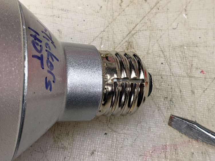
One of those LED spotlights may have barely outlasted its worthless warranty, but not by much, and has been languishing on the back of the bench with “Flickers hot” scrawled on its side.
The metal base didn’t respond to twisting, so I slit the threads with a cutoff wheel:
Satco PAR30 – thread slit
Applying the screwdriver removed the base to reveal a silicone rubber casting:
Satco PAR30 – thread silicone
The small wire emerging near the edge of the plastic case seems to be the neutral contact to the shell, with a poor enough joint to suggest it might have been why the lamp flickered when it got hot.
Some brute force snapped the silicone off at the bottom of the plastic case and broke the two wires bringing AC to the PCB:
Satco PAR30 – thread silicone base
Digging around inside produced a debris field of silicone crumbs, broken resistors, torn caps, and various other components, with zero progress toward removing the shell:
Satco PAR30 – silicone extraction
A little lathe work converted a chunk of PVC pipe into a crude mandrel supporting the mangled case:
Satco PAR30 – base cutting setup
A few millimeters of sissy cuts released a silicone O-ring sealing the shell against the reflector:
Satco PAR30 – O-ring seal
Continuing the cuts eventually revealed the three screws holding the shell to the reflector and the two wires powering the LED:
Satco PAR30 – reflector separated
Chopping off the screws with a diagonal cutter freed the shell and revealed the top of the PCB:
Satco PAR30 – electronics top
It really does have a surprising number of components!
Those three screws connected the LED panel / heatsink to the shell through the back of the double-walled reflector. More brute force peeled the outer shell away and released the panel:
Satco PAR30 – lens assembly
Each of the 5050 packages contains a pair of white LEDs with 5.2 V forward drop for the pair, at the very low test current. They’re all in series, so you’re looking at well over 60 V total forward drop:
Satco PAR30 – LED panel detail
Note that the wiring, which nobody will ever see, follows the electrical color code of white = common and gray = hot.
Once again, the discrete LM3909 circuitry can blink a blue LED while running a pair of alkaline cells all the way down to about 1 V, with one cell ending at 0.2 V and the other at 0.8 V. They started out discharged to 1.2 V each during their useful life, then blinked for a month; it’s as good a use for dead cells as I can think of.
With another pair of not-dead-yet cells providing 2.4 V, it started up again:
Blue LM3909 2.4V alkaline – 042
That’s a frame from a short video taken in subdued light, just to show it really does work.