Ed Nisley's Blog: Shop notes, electronics, firmware, machinery, 3D printing, laser cuttery, and curiosities. Contents: 100% human thinking, 0% AI slop.
Having seen a few bikes with amber “headlights” and being desirous of reducing the number of batteries on Mary’s bike, this seems like an obvious first step:
The rest of the code gets a few cleanups you’d expect when you compile code untouched for a few years using the latest OpenSCAD.
The markers are allegedly DOT rated, which matters not for my use case: SAEP2PCDOT.
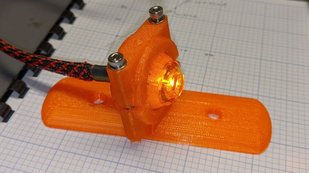
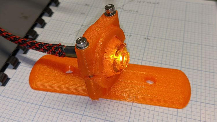
The mount is grossly overqualified for a wide-beam light with little need for aiming:
Fairing Mounted Side Marker – test light
Eventually, the marker should slip into a prealigned cylindrical holder, with a dab of epoxy to keep it there.
The lights are a buck apiece, so there’s no reason to form a deep emotional attachment. They are the usual poorly molded and badly assembled crap, although the next step up from a nominally reputable supplier is a factor of five more expensive.
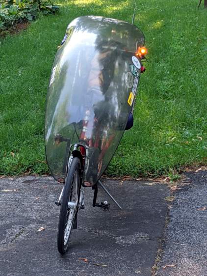
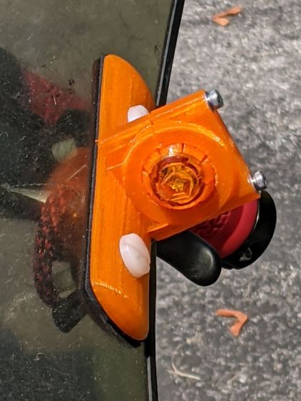
It’s generated for the left side of the fairing, although I think having a pair of them would improve conspicuity:
Fairing Mounted Side Marker – installed
Being automotive, it runs from a 12 V supply, which comes from a boost converter driven by the Bafang 6 V headlight output. The absurdity of bucking a 48 V lithium battery to a 6V switched headlight output, then boosting it to 12 V to drive a single amber LED with a 1.5 V forward drop does not escape me.
It’s possible to slice the lens off (using a lathe), remove / replace the resistor, then glue it back together, which would be worthwhile if you were intending to drive it from, say, an Arduino-ish microcontroller to get a unique blink pattern.
Given the overall lack of build quality, it might make more sense to slap a condenser lens in front of a Piranha LED.
Although Gee’s Terry Symmetry is sized for female bodies, I managed to ride it up and down the driveway while watching the power display:
Voltage
52.5
Rated Current
24
Max current
18
Power
Power
PAS
Assist
Amp
Calc
Observed
Ratio
0
0%
0.0
0
0
~
1
4%
0.7
38
26
69%
2
6%
1.1
57
52
92%
3
9%
1.6
85
78
92%
4
13%
2.3
123
104
85%
5
20%
3.6
189
182
96%
6
30%
5.4
284
258
91%
7
50%
9.0
473
453
96%
8
85%
15.3
803
675
84%
9
100%
18.0
945
900
95%
Bafang BBS02 on Terry Symmetry – actual voltage
The variations in the last column suggest my data-taking is … wobbly, at best.
I think the displayed power does not come from actual current and voltage measurements, because recalculating the power using the nominal 48 V battery value produces an unnatural agreement:
Voltage
48
Rated Current
24
Max current
18
Power
Power
PAS
Assist
Amp
Calc
Observed
Ratio
0
0%
0.0
0
0
~
1
4%
0.7
35
26
75%
2
6%
1.1
52
52
100%
3
9%
1.6
78
78
100%
4
13%
2.3
112
104
93%
5
20%
3.6
173
182
105%
6
30%
5.4
259
258
100%
7
50%
9.0
432
453
105%
8
85%
15.3
734
675
92%
9
100%
18.0
864
900
104%
Bafang BBS02 on Terry Symmetry – nominal voltage
The motor controller may measure the actual winding currents while generating the BLDC waveforms, but the values may not be available to the display at the end of the cable. If Bafang documented the commands & responses, we’d know for sure, but they don’t.
Those assist values come from Mary’s Tour Easy, a much heavier bike than the Symmetry, but the first few levels work well in my limited tests. The highest levels may be too peppy for Gee’s normal routes, but having some serious boost in reserve can defang (hah) the worst hills.
Terry Symmetry – Tour Easy
IMO, the bike would burn rubber at the motor’s full 24 A current …
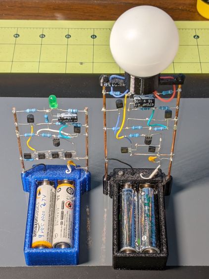
These two discrete LM3909 circuits recently stopped blinking:
LM3909 AA alkaline – Green and Blue
The green LED (on the left) took six months to wear its pair of not-dead-yet AA alkalines from 2.7 V down to nearly zero.
The blue LED in the radome took two months to go from 1.0 V (!) to nearly zero. It didn’t start very bright and went decidedly dim along the way, but the LM3909 circuitry still managed to jam a few microamps through the LED.
In both cases, one of the cells was reverse-charged by a few hundred millivolts, although neither leaked.
Both got another set of not-quite-dead AA cells and they’re back in action.
My friend rides about the same way we do, except from a much higher perch, so I’ll start her off with a configuration similar to the one we settled on for Mary’s Tour Easy.
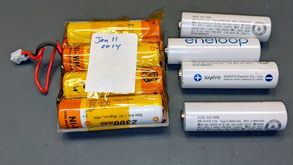
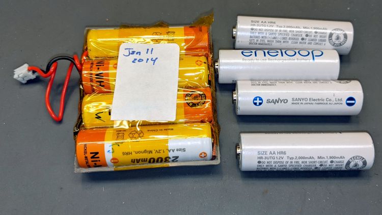
My old Aceco FC1002 frequency meter stopped working without being plugged into the charger. It runs from a quartet of NiMH cells taped into a tray I made seven years ago:
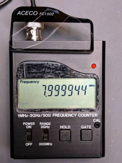
The faceplate bears the scars of its cracked acrylic (?) coating, so I pushed it out, traced the outline on a flat piece of polypropylene clamshell packaging, cut it out, and stuck it in place with tapeless sticky:
Aceco FC1002 – polypropylene faceplate
That removes the branding, but IMO improves the appearance.
It should continue working for another half decade or so!
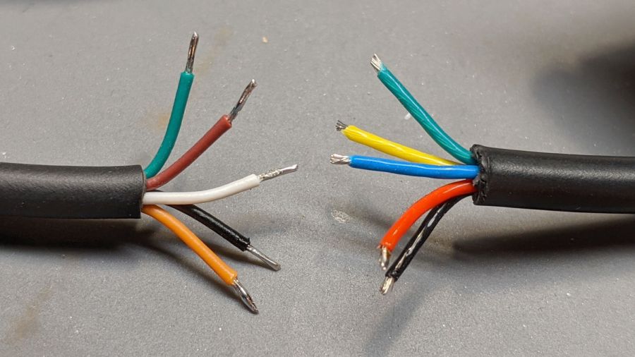
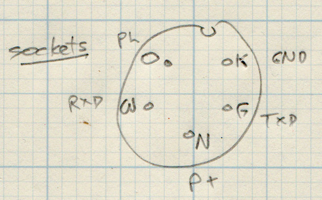
The new cable on the left seemed like it might match the canonical colors:
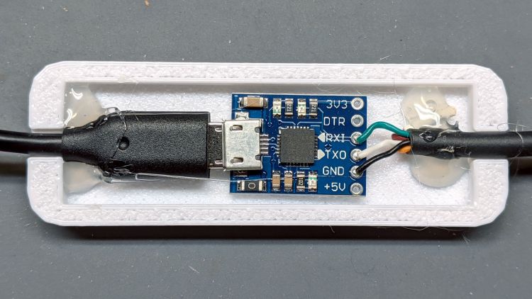
Bafang BBS02 display cable pinout
It comes heartbreakingly close:
Bafang Display Cable – extension colors
Brown and Orange connect as the naive user might expect, which does reduce the likelihood of incinerating the motor controller / USB adapter / laptop by connecting the 48 V battery directly to the logic-level electronics.
However, White wasn’t on the original menu, Green is now TXD, and Black has become, comfortingly, GND.
Verily, it is written: Hell hath no fury like that of an unjustified assumption.
This socket connector has a watertight shell making it extremely difficult to mate and unmate with the pin connector on the bike. Watertightness being unnecessary, a little razor-knife action seems in order:
Bafang Display Extension Cable – shroud trimming
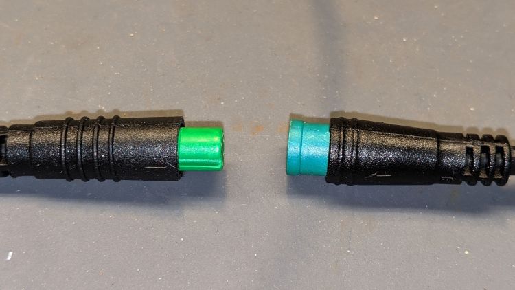
Visually, they’re both green-ish, but sometimes the Pixel camera accentuates any differences.
So these brief notes, compiled before I read the Okendo TOS, should serve the same purpose as an actual review, minus the nonsense of providing even more of my sensitive bits.
Bose discontinued their Hearphones last year. While I’m reasonably happy with how mine work, they seem to last about a year before something fails. Bose replaced the first unit after its covering delaminated, replaced the second unit when a wire failed in the left microphone, and the third unit is now approaching one year of steady use.
The Hearphone necklace curled around the IQbuds charging case:
Bose Hearphones – Nuheara IQbuds2 MAX
Comparing the IQBuds² MAX to the Bose Hearphones:
Heavier in the ears, but without the necklace
Poor battery runtime, both have non-replaceable batteries
Poor ear seal with silicone tips, OK with Nuheara’s foam tips
Immediate access to “World off” mode!
“World off” mode seems noisier, even with ANC on
Better dynamic noise control / filtering
The tradeoff for not having the Bose necklace is, of course, carrying a smaller battery in each ear. Everybody’s claimed run times are optimistic, but after a year the Hearphones still last the better part of a day, while new IQbuds generate range anxiety after a morning and must then spend a while recharging in their case.
The stock IQbud silicone tips exert entirely too much pressure on my ear canals. The foam tips produce a much better seal and were easier to wear for more than a few hours. The Bose “Stayhear” shaped silicone tips fit much better and suppress external sound just as well as the IQbud foam tips.
Replacing the stock IQbuds foam tips (described as “Comply memory foam”) with actual Comply memory foam tips directly from Comply was a definite step up that should not be necessary; they are similar, but visibly different. According to Comply’s online fit selector, you need their Isolation T-167 Sennheiser-specific tips, even though Nuheara hardware appears in Comply’s selector.
The IQbuds tap controls, except for the simplest single tap, barely work. I cannot perform a double-tap, because the bud registers the first tap as a single tap and either discards the second tap or registers it as another single tap. Long taps generally work, except when they don’t, having nothing to do with tap duration or force. Tech support tells me the buds use the audio signal to determine when a finger taps the bud, but AFAICT tap sensitivity is much too high and the discrimination entirely too unfussy.
Amusingly, nibbling dark chocolate can produce exactly the correct audio signal to trigger the “World off” tap in the right bud and, occasionally, the “Play / Pause” tap in the left bud. I rest my case.
For someone requiring far more audio gain than a typical hipster, firmly tapping an ear bud is an … uncomfortable … user interface.
Fortunately, a single correctly executed tap on the right bud mutes the microphones and turns on Active Noise Cancellation; the Hearphones bury that vital function on a tiny icon inside the Bose app, requiring many seconds to start and activate.
The IQbuds app (and, presumably, the bud firmware) does not allow assigning any tap function to any bud + tap pattern. For example, there’s no way to access both “change location” and “change focus” by tapping, because both those functions can be activated only by the right bud’s long tap: you may select one or the other. Weirdly, volume and media controls appear nearly everywhere and, if double taps worked, they’d be useful.
The Hearphones are much better at muting relatively quiet ambient sound, to the extent that I thought the IQbud “World off” function didn’t work. It does, even though it seems tuned to suppress much higher noise levels. Both do a surprisingly good job suppressing loud yard tools, perhaps due to my inability to hear frequencies over a few kHz.
The IQbud noise suppression exhibits horrible gain pumping in noisy environments and windy conditions. It rolls off the overall gain and filters the higher frequencies as the ambient noise increases, then restores them in a rush as the noise subsides: repeating the cycle as the noise level changes. This is very unpleasant and, AFAICT, there is no way to forcibly set a specific gain / bandwidth other than turning the suppression completely off, which misses the point.
Bottom line: I use the IQbuds and they definitely help my hearing, but I don’t particularly like them.
To be fair, I don’t like the Hearphones necklace very much, either, even though, overall, Bose did a better job with the actual earpieces.