Ed Nisley's Blog: Shop notes, electronics, firmware, machinery, 3D printing, laser cuttery, and curiosities. Contents: 100% human thinking, 0% AI slop.
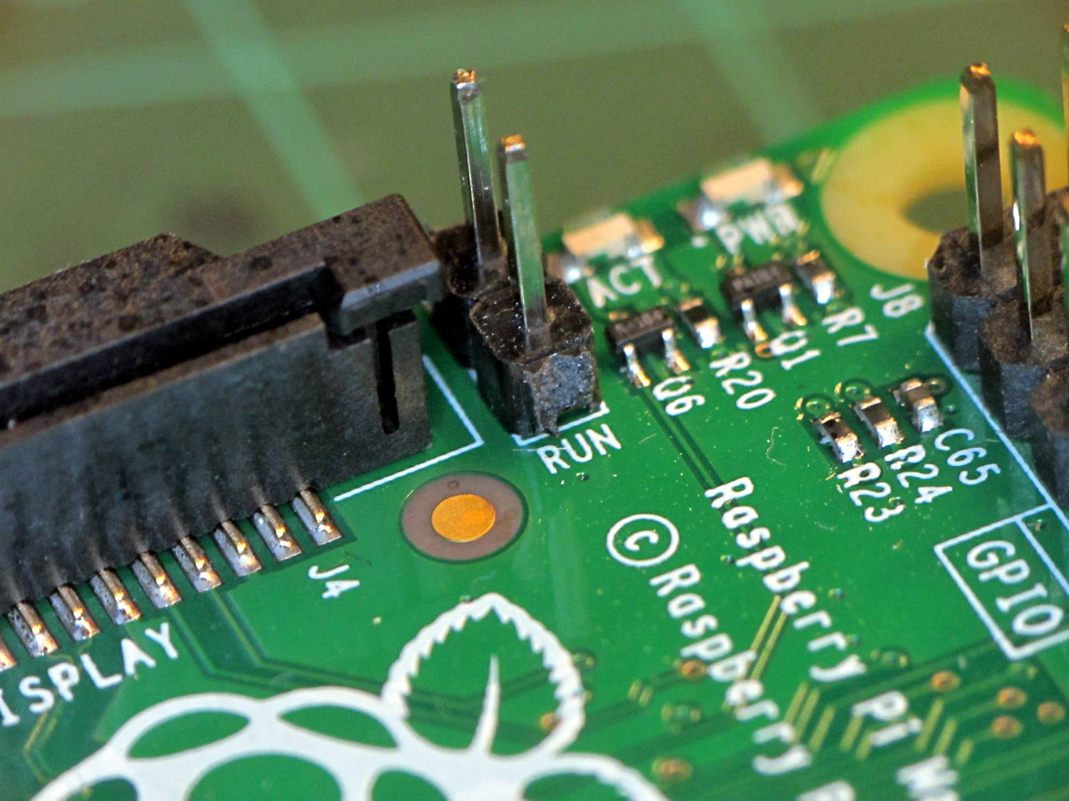
Turns out Raspberry Pi boards have provision for a Reset switch, but you gotta dig for it. On the Model B+, it’s labeled RUN:
Raspberry Pi BPlus – RUN header
Soldering in that 2-pin header and plugging a pushbutton switch on a short cable will suffice until I get around to thinking of / scrounging a suitable case.
Poking the button forces a power-on reset, which you shouldn’t do with the RPi running, lest you trash the filesystem. After shutting down with sudo halt, however, the switch does exactly what’s needed: restarts the CPU from scratch.
The RPi draws little enough power that there’s no point in actually pulling the plug; stressing that Micro-B connector is definitely a Bad Idea.
I did a lightning talk / show-n-tell last Tuesday at the MHV LUG meeting and covered one end of a table with the Neopixel-lit bulbs & vacuum tubes & hard drive platters I’ve been playing with:
The ceramic ring screws down around the socket shell and pulls it up against the base; the threads have only as much precision as required to keep it from falling off. I may need to add a leveling shim just so I don’t have to explain why it’s always crooked.
Having that knockoff Neopixel fail from overheating prompted me to measure what was going on. Because the LEDs sink most of their heat into the package leads, the back of the LED strip should be the hottest part of the package and the Mood Light’s central pillar should be pretty nearly isothermal. Despite that, I figured I should measure the temperature closer to the back of the strip, sooo I drilled a hole for the thermocouple…
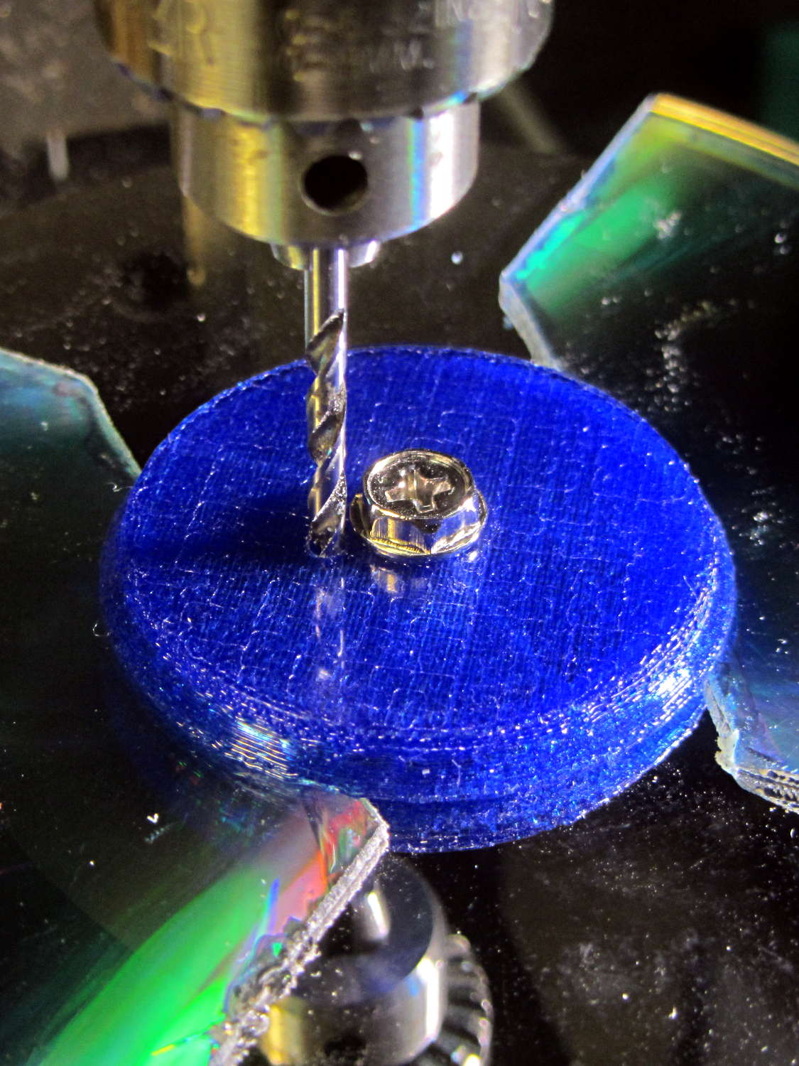
Clamp the whole Mood Light to the Sherline’s tooling plate with the pillar sides mostly square to the axes and line up the spindle 2 mm behind the LED strip:
Mood Light – aligning thermocouple hole
The two clamp pads are CD chunks, under just enough pressure to anchor the Mood Light.
Screw the cap in place (to match-drill both holes at once) and drill a 2 mm (#46, close enough) hole down past the top LED:
Mood Light – drilling thermocouple hole
I tucked the Mood Light into a box to ward off breezes, jammed one thermocouple into the new hole, let another float over the top platter, then forced the Neopixels to display constant grayscale PWM values (R=G=B) while recording the LED and air temperatures every five minutes:
Hard Drive Mood Light – temp vs power data
That was easier and faster than screwing around with automated data collection. The data has some glaring gaps where I went off to do other things during the day.
I turned those numbers into a graph, printed it out, puzzled over it for a bit, then annotated it with useful numbers:
Hard Drive Mood Light – temp vs power data – graph
That first little blip over on the left comes from a minute or two at PWM 32; the cooling time constant works out to be a bit under 10 minutes. The warming time constant looks to be somewhat longer, but not by much.
Eyeballing the endpoint temperatures for each PWM value, feeding in the current measurements, and creating a small table:
VCC
5
V
Current
0.057
A
Package
0.285
W
Total
3.42
W
PWM
Duty
Nom Power
Failed LEDs
Net Power
°C Rise
0
0.00
0.00
0
0.00
0
32
0.13
0.43
0
0.43
6
64
0.25
0.86
0
0.86
12
85
0.33
1.14
1
1.04
16
128
0.50
1.71
1
1.62
24
192
0.75
2.57
1
2.47
35
255
1.00
3.41
4
3.03
42
The same blue LED that failed earlier dropped out again, plus another package (on a different strip) went completely dark shortly after I clobbered the LEDs with full power at PWM 255. The Net Power column deducts the power not used by the failed LEDs, under the reasonable assumption that the total heating depends on the number of active LEDs.
All the failed LEDs worked fine when they cooled to room temperature, so, whatever the failure mode might be, it’s not permanent. The skimpy WS2812B datasheet says bupkis about a protective thermal shutdown circuit, although it specs an 80 °C maximum operating junction temperature. I’ll stipulate a 20 °C temperature difference from junction to thermocouple at PWM 255, but that doesn’t explain the first blue LED failure at PWM 85.
Methinks these knockoffs will be much happier operating in the mid-30s.
Turning the last two columns of that table into a graph (minus the PWM 0 line to let the intercept float around) looks like I’m faking it:
Hard Drive Mood Light – Temperature vs Power
The Y intercept is off by less than 1 °C, which seems pretty good under the circumstances. The kink at PWM 85 shows that I probably didn’t allow enough time for the temperature to stabilize after the blue LED failed.
So, in round numbers, the thermal coefficient for a dozen knockoff Neopixels on a plastic pillar inside a stack of hard drive platters works out to 14 °C/W.
The raised sine waves in the Mood Light produce a long-term average PWM half of their maximum PWM. They’ve been perfectly happy with MaxPWM = 64 pushing them barely 6 °C over ambient, so they should continue to work fine at PWM 128 for a 12 °C rise… except, perhaps, during the hottest of mid-summer days.
Obviously, I should jam a thermistor inside the column and have the Arduino wrap a feedback loop around the column temperature…
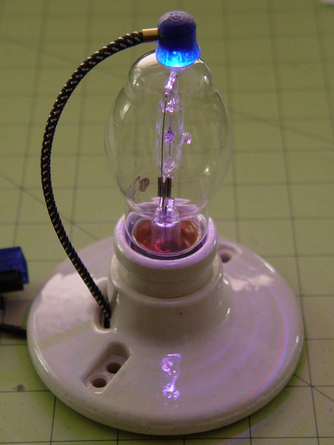
This lamp needs a base for its (minimal) electronics:
Vacuum Tube LEDs – plate lead – overview
The solid model won’t win many stylin’ points:
Vacuum Tube Lights – lamp base solid model
It’s big and bulky, with a thick wall and base, because that ceramic lamp socket wants to screw down onto something solid. The screw holes got tapped 6-32, the standard electrical box screw size.
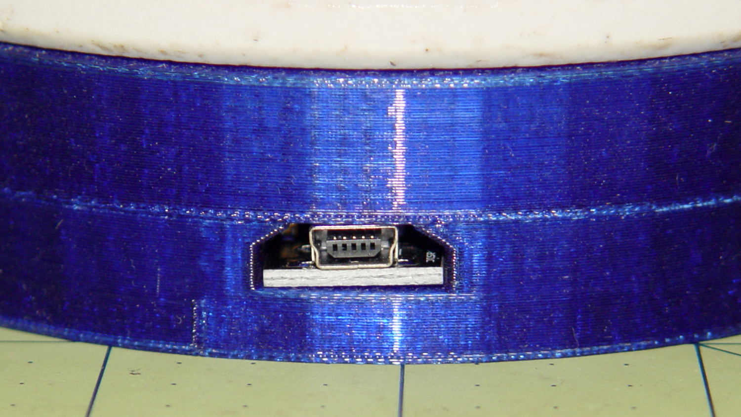
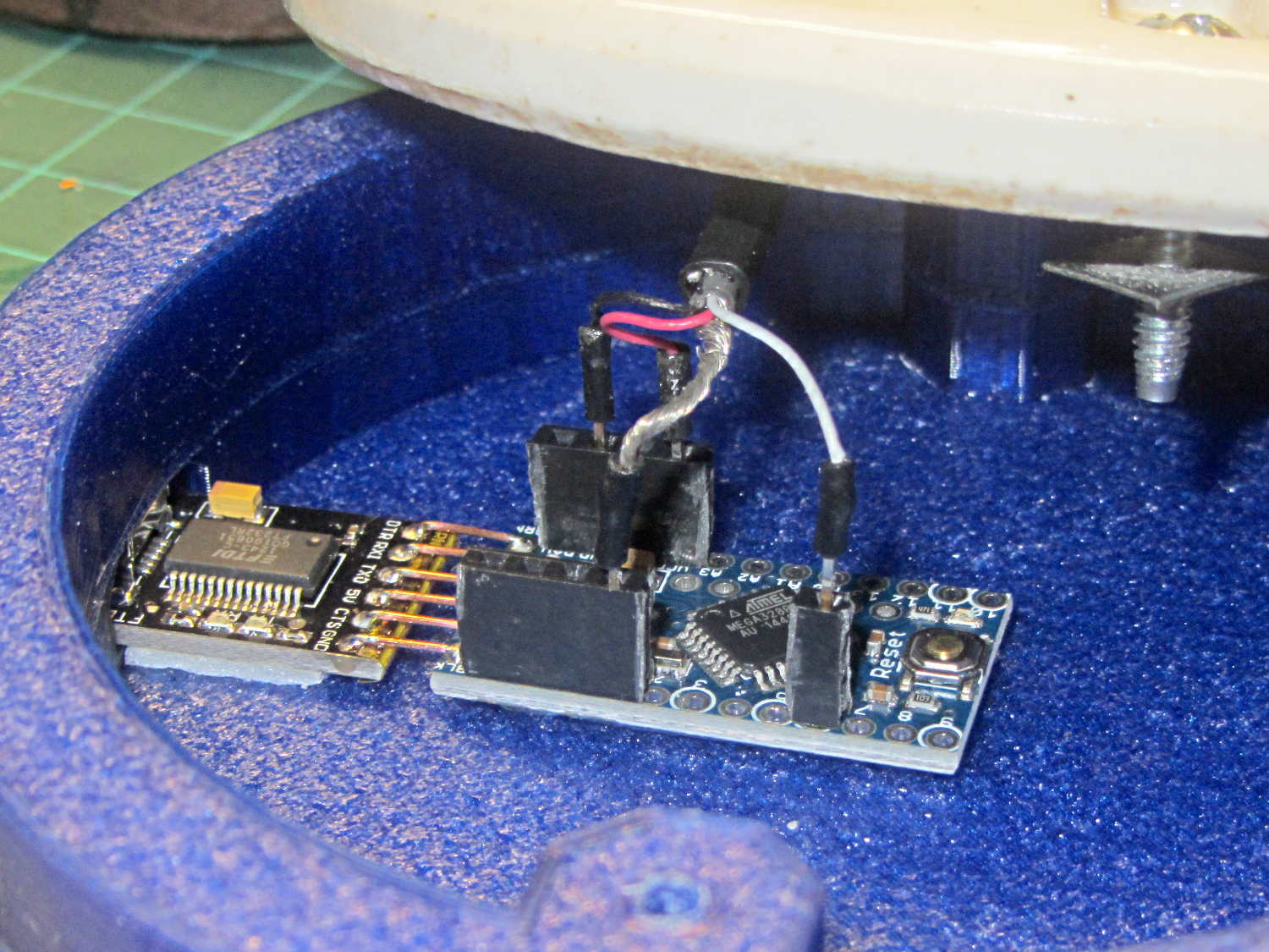
The odd little hole on the far side accommodates a USB-to-serial adapter that both powers the lamp and lets you reprogram the Arduino Pro Mini without tearing the thing apart:
Vacuum Tube Lights – USB adapter cutout
The sloped roof makes the hole printable in the obvious orientation:
Lamp Base – USB port
There’s an ugly story behind the horizontal line just above the USB adapter that I’ll explain in a bit.
The adapter hole begins 1.2 mm above the interior floor to let the adapter sit on a strip of double-sticky foam tape. I removed the standard header socket and wired the adapter directly to the Arduino Pro Mini with 24 AWG U-wires:
Lamp Base – interior
I didn’t want to use pin connectors on the lamp cable leads, but without those you (well, I) can’t take the base off without un-/re-soldering the wires in an awkward location; the fact that I hope to never take it apart is irrelevant. Next time, I’ll use a longer wire from the plate cap and better connectors, but this was a trial fit that became Good Enough for the purpose.
And then It Just Worked… although black, rather than cyan, plastic would look spiffier.
Bluish phases look icy cold:
Vacuum Tube LEDs – halogen lamp – purple phase
Reddish phases look Just Right for a hot lamp:
Vacuum Tube LEDs – halogen lamp – red phase
A ring of white double sided foam tape now holds the plate cap in place; that should be black, too.
The OpenSCAD source code adds the base to the plate cap as a GitHub gist:
This file contains hidden or bidirectional Unicode text that may be interpreted or compiled differently than what appears below. To review, open the file in an editor that reveals hidden Unicode characters.
Learn more about bidirectional Unicode characters
A single (knockoff) Neopixel hovers over a defunct halogen bulb:
Vacuum Tube LEDs – plate lead – overview
The Arduino code comes from stripping down the Hard Drive Platter Mood Light to suit just one Neopixel, with the maximum PWM values favoring the red-blue-purple end of the color wheel:
Unlike the Mood Light’s dozen Neopixels jammed into the platter’s hub ring, running one Neopixel at full throttle atop the tube doesn’t overheat the poor controller. In a 22 °C room, PWM 255 white raises the cap’s interior temperature to 35 °C, which looks like a horrific 40 °C/W thermal coefficient if you figure the dissipation at 300 mW = 5 V x 60 mA.
Feeding those parameters into the raised sine wave equation causes the cap to tick along at 27 °C for an average dissipation of 120 mW, which sounds about right:
113 mW = 5 V x (20 + 20 + 5 mA) / 2
The effect is striking in a dark room, but it’s hard to photograph; the halogen capsule inside the bulb resembles a Steampunk glass jellyfish:
Vacuum Tube LEDs – plate lead – detail
That ceramic light socket should stand on a round base with room for the Arduino controller. I think powering it from a wall wart through a USB cable makes sense, with a USB-to-serial converter epoxied inside the box for reprogramming.
It looks pretty good, methinks, should you like that sort of thing.
This file contains hidden or bidirectional Unicode text that may be interpreted or compiled differently than what appears below. To review, open the file in an editor that reveals hidden Unicode characters.
Learn more about bidirectional Unicode characters
Lighting up that old voltage regulator tube conclusively demonstrated there’s no point in conjuring high voltages in this day & age. Nay, verily, merely lighting the filament of some tubes would require more power than seems reasonable.
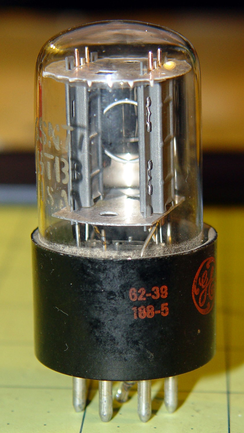
With only a slight loss of historical accuracy, one could light the tube from the top with a Neopixel LED tucked into a similar cap, with power-and-data arriving through a suitably antiqued flying lead. That won’t work on tubes like that 1B3GT with an actual plate terminal at the top, nor with small Noval / miniature 7-pin tubes topped with an evacuation tip, but it’s fine for tubes like this 6SN7GTB:
6SN7GTB Vacuum Tube
Obviously, you want a relatively small cap atop the tube, lest the LED visually overwhelm the tube. Some preliminary tests (a.k.a. screwing around) showed that the mica spacer holding the dual triode elements together lights up wonderfully well and diffuses the glow throughout the tube.
Some PET braid tucked into a snippet of brass tubing dresses up a length of what might once have been audio cable. The braid wants to fray on the ends; confining it with heatstink or brass tubing is mandatory.
That’s a 1 µF ceramic SMD cap soldered between the +5 V and Gnd traces, atop a snippet of Kapton tape, in the hopes that it will help the 100 nF cap (on the other side of the board) tamp down the voltage dunks from PWM current pulses through that long thin wire. The leads come off toward the center to bend neatly upward into the cap.
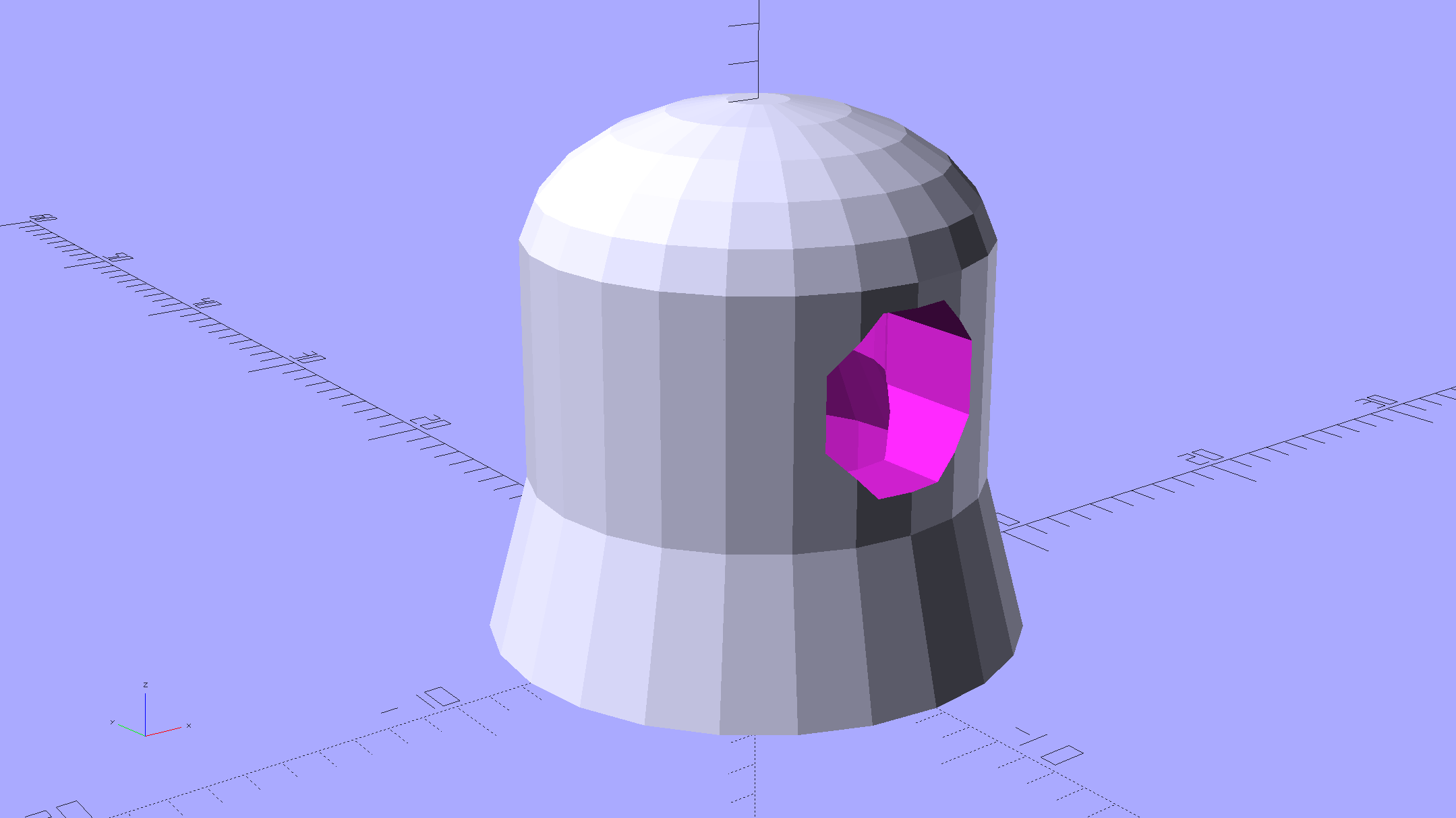
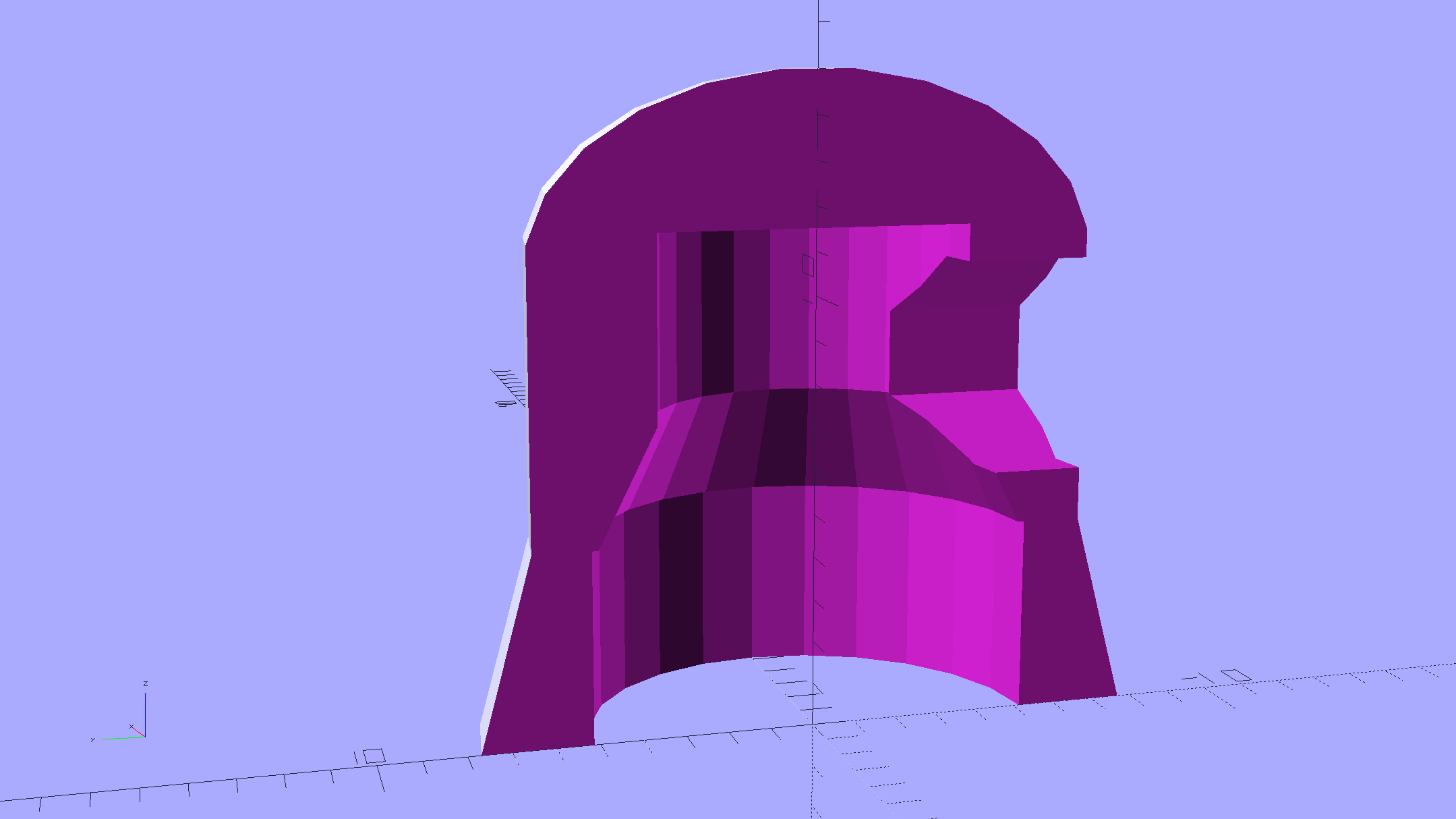
Duplicating that old plate cap on the 1B3GT would be a fool’s errand, so I went full frontal Vader:
Vacuum Tube Lights – cap solid model – Overview
The interior recesses the LED far enough to allow for the tube’s top curvature, with a conical adapter to the smaller wiring channel that allows for more plastic supporting the brass tube:
Vacuum Tube Lights – cap solid model – section
A glob of epoxy inside the cap anchors the PCB and fuses all the loose ends / floppy wires / braid strands into a solid block that will never come apart again.
It should be printed (or primered and painted) with opaque black or maybe Bakelite Brown, but right now I have cyan PETG and want to see how it plays, soooo:
Vacuum Tube LEDs – plate lead – overview
The cap floats in mid-air over a defunct Philips 60 W halogen bulb that I’ve been saving for just such an occasion. Obviously, you must epoxy / glue the cap in place for a permanent display.
This file contains hidden or bidirectional Unicode text that may be interpreted or compiled differently than what appears below. To review, open the file in an editor that reveals hidden Unicode characters.
Learn more about bidirectional Unicode characters