The Smell of Molten Projects in the Morning

Ed Nisley's Blog: Shop notes, electronics, firmware, machinery, 3D printing, laser cuttery, and curiosities. Contents: 100% human thinking, 0% AI slop.

Category: Electronics Workbench

Electrical & Electronic gadgets

  • ATX Lithium Ion 18650 Cell Capacity

    The 2016-11A and 2016-11B cells produced the overlapping red and green curves, with the gritty section due to crappy battery pack connections:

    Li-Ion 18650 cells - ATX prot - bare - Ah scale - 2016-12-17
    Li-Ion 18650 cells – ATX prot – bare – Ah scale – 2016-12-17

    The lower curve comes from an old unprotected cell harvested from a defunct media player and retrieved from the to-be-recycled pile.

    I picked 1 A as a reasonable value for their intended use in flashlights and maybe a helmet camera. Unlike some other cells in the recent past, these deliver 3.0 A·h, reasonably close to their rated 3.4 A·h capacity at a (presumably) lower current.

    Replotting the voltage vs. energy delivered doesn’t show any surprises:

    Li-Ion 18650 cells - ATX prot - bare - Wh scale - 2016-12-17
    Li-Ion 18650 cells – ATX prot – bare – Wh scale – 2016-12-17

    The voltage declines more-or-less linearly, without the relatively flat discharge curve for smaller cells, which explains why the J5 V2 flashlight becomes seriously dim after a few hours. On the upside, that allows a reasonably accurate state-of-charge display.

    Assuming the Sony HDR-AS30V camera burns 0.1 W·h/min while recording (which is a fancy way of saying it dissipates 6 W), then it should run for (10 W·h)/(0.1W·h/min) = 100 min from one of these cells fitted as an outrigger. The best of the NP-BX1 cells for the camera delivers something like 90 minutes from a measured capacity of 4 A·h at 500 mA; I don’t know what to make of those numbers. Perhaps the camera runs the NP-BX1 cells below the 2.8 V cutoff I’ve been assuming?

  • Fordham FG-801 Function Generator Recalibration

    While I had the case open, I checked the FG-801’s calibration:

    Fordham FG-801 Fn Gen - circuit board
    Fordham FG-801 Fn Gen – circuit board

    Look at all those parts!

    The raw filtered DC power supplies run a bit high and the output voltages & frequencies were off by a little, but not too much after all these years.

    Page 11 of the instruction manual gives the setup and calibration adjustments (clicky for more dots):

    Fordham FG-801 Manual - Page 11
    Fordham FG-801 Manual – Page 11

    Page 12 gives some values that should be true:

    Fordham FG-801 Manual - Page 12
    Fordham FG-801 Manual – Page 12

    For whatever reason, the manual isn’t available on The InterWebs, so here it is for your amusement:

    Fordham FG-801 Sweep Function Generator – Instruction Manual.pdf

  • Fordham FG-801 Function Generator Power Switch

    The power switch in my trusty Fordham FG-801 Function Generator failed with an accumulation of oxidation / crud on the contacts. That’s fix-able, but the switch contained not one, but two powerful springs, and puked its guts all over the floor around the Squidwrench Operating Table. Even with (a preponderance of) the parts in hand, I couldn’t figure out how to reassemble the thing; the only way out was to replace the switch.

    The OEM switch had a 0.360+ inch diameter pushbutton that fit into a ⅜ inch hole and, alas, my remaining stock of line-voltage switches had toggle levers and used ¼ inch holes. So I converted a bit of aluminum rod into a suitable bushing:

    Fordham FG-801 Fn Gen - new switch hardware
    Fordham FG-801 Fn Gen – new switch hardware

    The lock washer in the middle started with a much wider tab that I filed down into a tooth for the dent from a #2 center drill. Protip: center drills don’t walk off like twist drills, even when you hand-hold the front panel at the drill press with all the electronics dangling below.

    The bushing dimension doodle:

    Fordham FG-801 Function Generator - Replacement Switch Bushing
    Fordham FG-801 Function Generator – Replacement Switch Bushing

    The internal wiring routes the 120 VAC line conductor to the switch, then to the fuse, then to the transformer. I don’t know whether it’s better to have an unfused switch or an unswitched fuse (surely there’s a UL spec for that), but I didn’t change anything. The new switch, being slightly smaller and mounting directly on the panel, required a new wire (the blue one) from the fuse:

    Fordham FG-801 Fn Gen - power switch - installed
    Fordham FG-801 Fn Gen – power switch – installed

    The OEM switch mounted on two round brass standoffs and, wonder to tell, the new switch fit between them!

    From the front, the new switch looks like it grew there:

    Fordham FG-801 Fn Gen - switch in action
    Fordham FG-801 Fn Gen – switch in action

    The PCB mounts to the top of the case with one screw and four hexagonal brass standoffs. The standoffs have 6-32 tapped holes on one end and a 6-32 stud on the other; one of those stud had broken off. A 6-32 stainless steel screw secured in a clearance hole with a dab of epoxy solved that problem:

    Fordham FG-801 Fn Gen - standoff stud
    Fordham FG-801 Fn Gen – standoff stud

    I stood it vertically and tweaked the screw to be perpendicular while the epoxy cured.

    Memo to Self: The next time around, put a nut on the stud to make sure the answer comes out right. I didn’t do this time to avoid epoxying the nut to the standoff.

    Done!

  • Loop Antenna Splice Reinforcement

    Those solder joints and finicky little wires seem much too fragile on their own:

    LF Loop Antenna - complete joint
    LF Loop Antenna – complete joint

    This should help:

    Loop Antenna Splice - assembled
    Loop Antenna Splice – assembled

    Foam blocks hold the ribbon cable in place and provide a bit of strain relief around the hard plastic edge:

    Loop Antenna Splice - hardware
    Loop Antenna Splice – hardware

    The brass inserts in the bottom block (on the left) got epoxied in place, because they must provide quite a bit of force to clamp the foam. Their larger knurled end sits flush with the outside surface and the smaller end has one thread thickness of clearance below the inner surface.

    A last look at the wiring:

    Loop Antenna Splice - wiring
    Loop Antenna Splice – wiring

    I think the preamp must sit at some distance from the antenna to prevent feedback, but that remains to be seen.

    The M2’s nozzle accumulated a huge blob of PETG that turned into a giant smear:

    Loop Antenna Splice - PETG booger
    Loop Antenna Splice – PETG booger

    Fortunately, it’s on the inside where nobody will ever see it. If you know where to look, it’s barely visible from the outside.

    The solid model shows off the structure a bit better:

    Loop Antenna Splice - show view
    Loop Antenna Splice – show view

    The inside view:

    Loop Antenna Splice - bottom
    Loop Antenna Splice – bottom

    The OpenSCAD source code as a GitHub Gist:

    // Ribbon cable loop antenna splice
    // Ed Nisley KE4ZNU December 2016
    Layout = "Text";
    //- Extrusion parameters must match reality!
    ThreadThick = 0.25;
    ThreadWidth = 0.40;
    HoleWindage = 0.2;
    Protrusion = 0.1; // make holes end cleanly
    inch = 25.4;
    function IntegerMultiple(Size,Unit) = Unit * ceil(Size / Unit);
    //———-
    // Dimensions
    Cable = [200,48.0,1.5]; // X = longer than anything else
    Splice = [15.0,53.0,5.0]; // epoxy blob around joints
    Foam = [15.0,Splice[1],2.0];
    CornerRadius = 5.0;
    ID = 0;
    OD = 1;
    LENGTH = 2;
    Insert = [3.9,4.6 – 0.1,5.8]; // 4-40 knurled brass insert
    Screw = [2.7,5.5,2.0]; // OD = head LENGTH = head thickness
    Washer = [3.0,8.0,0.8];
    BlockOA = [60.0, // convenient length
    Splice[1] + 4*Washer[OD], // clearance around washer on top
    2*(Insert[LENGTH] + 2*ThreadThick)]; // insert sets both thicknesses
    NumScrews = 2; // screws along each side of cable
    ScrewOC = [BlockOA[0] / NumScrews,
    BlockOA[1] – 2*Washer[OD],
    2*BlockOA[2] // ensure complete holes
    ];
    TextThick = 3*ThreadThick; // depth of text into surface
    TextFit = HoleWindage/2; // clearance around text polygons
    //———————-
    // Useful routines
    module PolyCyl(Dia,Height,ForceSides=0) { // based on nophead's polyholes
    Sides = (ForceSides != 0) ? ForceSides : (ceil(Dia) + 2);
    FixDia = Dia / cos(180/Sides);
    cylinder(d=(FixDia + HoleWindage),h=Height,$fn=Sides);
    }
    //—–
    // Blocky model of cable + splice + wire tap for subtraction
    module Antenna() {
    union() {
    cube(Cable,center=true);
    cube(Splice,center=true);
    for (i=[-1,1])
    translate([0,-Splice[1]/2,0])
    cube([Splice[0]/2,Splice[1],2*Foam[2]],center=true);
    }
    }
    // Outside shape of splice Block, less screw clearance
    module SpliceBlock() {
    difference() {
    hull()
    for (i=[-1,1], j=[-1,1])
    translate([i*(BlockOA[0]/2 – CornerRadius),j*(BlockOA[1]/2 – CornerRadius),-BlockOA[2]/2])
    cylinder(r=CornerRadius,h=BlockOA[2],$fn=4*8);
    for (i = [0:NumScrews – 1], j=[-1,1])
    translate([-BlockOA[0]/2 + ScrewOC[0]/2 + i*ScrewOC[0],j*ScrewOC[1]/2,-(BlockOA[2]/2 + Protrusion)])
    PolyCyl(Screw[ID],BlockOA[2] + 2*Protrusion,6);
    }
    }
    // Splice block less cable
    module ShapedBlock() {
    difference() {
    SpliceBlock();
    Antenna();
    }
    }
    // Bottom
    module BottomPlate() {
    difference() {
    ShapedBlock();
    translate([0,0,BlockOA[2]/2])
    cube(BlockOA + 2*[Protrusion,Protrusion,0],center=true);
    Antenna(Splice);
    for (i = [0:NumScrews – 1], j=[-1,1])
    translate([-BlockOA[0]/2 + ScrewOC[0]/2 + i*ScrewOC[0],j*ScrewOC[1]/2,-(BlockOA[2]/2 + Protrusion)])
    PolyCyl(Insert[OD],2*Insert[LENGTH],6);
    for (i=[-1,1])
    translate([i*((BlockOA[0] – Foam[0] + Protrusion)/2),0,(BlockOA[2]/2 – Cable[2]/2 – Foam[2])])
    cube([Foam[0] + Protrusion,Foam[1],BlockOA[2]],center=true);
    }
    }
    // Top
    module TopPlate() {
    difference() {
    ShapedBlock();
    translate([0,0,-BlockOA[2]/2])
    cube(BlockOA + 2*[Protrusion,Protrusion,0],center=true);
    Antenna(Splice);
    for (i=[-1,1])
    translate([i*((BlockOA[0] – Foam[0] + Protrusion)/2),0,-(BlockOA[2]/2 – Cable[2]/2 – Foam[2])])
    cube([Foam[0] + Protrusion,Foam[1],BlockOA[2]],center=true);
    rotate(90) {
    translate([0,6,BlockOA[2]/2 – TextThick])
    TextHack("KE4ZNU",8,0.0,1.15,TextThick + Protrusion);
    translate([0,-6,BlockOA[2]/2 – TextThick])
    TextHack("2016·12",6,0.0,1.20,TextThick + Protrusion);
    }
    }
    }
    module TextHack(Text="sample",Size=10,Offset=0.0,Space=1.0,Thick=ThreadThick) {
    linear_extrude(height=Thick,convexity=10)
    offset(r=Offset)
    text(Text,font=":bold",size=Size,spacing=Space,halign="center",valign="center");
    }
    //———-
    // Build them
    if (Layout == "Antenna")
    Antenna();
    if (Layout == "SpliceBlock")
    SpliceBlock();
    if (Layout == "ShapedBlock")
    ShapedBlock();
    if (Layout == "Bottom")
    BottomPlate();
    if (Layout == "Top")
    TopPlate();
    if (Layout == "Text") {
    translate([0,6,0])
    TextHack("KE4ZNU",8,-TextFit,1.15,TextThick);
    translate([0,-6,0])
    TextHack("2016·12",6,-TextFit,1.20,TextThick);
    }
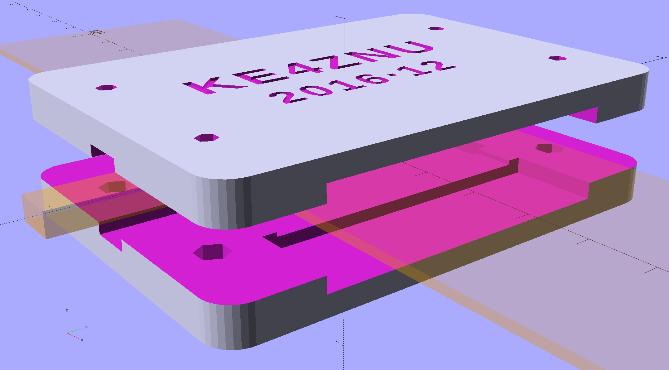
    if (Layout == "Show") {
    translate([0,0,5])
    TopPlate();
    translate([0,0,-5])
    BottomPlate();
    color("Orange",0.2)
    Antenna();
    }
    if (Layout == "Build") {
    translate([0,-0.6*BlockOA[1],BlockOA[2]/2])
    rotate([180,0,0])
    TopPlate();
    translate([0,0.6*BlockOA[1],BlockOA[2]/2])
    BottomPlate();
    }
  • Maxell CR2032 Lithium Cell: Early Failure

    The Hobo datalogger buried in the dirt under the patio kvetched about a low battery, which produced this surprising result:

    Maxell CR2032 cell - early failure
    Maxell CR2032 cell – early failure

    Cells from the same lot have been doing just fine in the other dataloggers, so I hope this is a one-off weak cell and not the harbinger of another run of dead cells.

  • Under-cabinet Lamp Brackets: Close-fit Power Plug

    Adding a little tab to the angled brackets prevents them from pivoting while you’re tightening the mounting screw into the brass insert:

    Kitchen Light Bracket - angled lip - Slic3r preview
    Kitchen Light Bracket – angled lip – Slic3r preview

    The trick with those tabs is to chop ’em off halfway to the tip, because there’s no point trying to print a wedge that ends with a sharp edge:

    Kitchen Light Bracket - angled - tab cutoff - solid model
    Kitchen Light Bracket – angled – tab cutoff – solid model

    Generating & positioning that block goes a little something like this:

    translate([0,
               2*MountBlock[1] - LEDEndBlock[2]*sin(StripAngle),
               MountBlock[2]/2 + MountHeight - 0.5*LEDEndBlock[2]*cos(StripAngle)])
        cube(2*MountBlock,center=true);


    As a rule of thumb, there’s no point in fussing with smaller shapes when a big one will suffice…

    This LED strip fits under the cabinet over the butcher block countertop next to the stove, which turns out to be Just Barely longer than the strip itself:

    Under-cabinet light - cramped power plug
    Under-cabinet light – cramped power plug

    The OEM straight-on coaxial plug (near the bottom of the picture) attached to the wall wart cable obviously wouldn’t fit in the available space, so I gimmicked up a right-angle adapter by the simple expedient of shortening the solder lugs of a plug from the heap (which, admittedly, doesn’t quite fully seat in the socket), bending them sideways, soldering a pair of wires, heatshrinking appropriately, then coating wires + plug with JB Kwik epoxy. The other end of the wires gets a coaxial jack that miraculously fits the OEM plug, styled up with more heatshrink tubing. Not pretty, but nobody will ever see it.

    Unlike the LED strip under the other cabinet, this IR proximity sensor doesn’t mind having a wood edge next to it and, thus, didn’t need a strip of tape to keep it happy.

  • 60 kHz Preamp: Simulation

    This circuitry descends directly from a QEX article (Nov/Dec 2015, p 13) by John Magliacane, KD2BD: A Frequency Standard for Today’s WWVB. The key part, at least for me, is a 60 kHz preamplifier using a resonant-tuned loop antenna and an instrumentation amplifier to reject common-mode interference from local electrostatic fields.

    I tinkered up an LTSpice IV simulation using somewhat more contemporary parts (clicky for more dots):

    60 kHz Preamp - LTSpice schematic
    60 kHz Preamp – LTSpice schematic

    The simulation quickly revealed that the original schematic interchanged the filter amp’s pins 2 and 3; the filter doesn’t work at all when you swap the + and – inputs.

    The stuff in the dotted box fakes the loop antenna parameters, with a small differential AC signal that injects roughly the right voltage to simulate a nominal 100 µV/m WWVB field strength. I biased the center tap to the DC virtual ground at + 10 V and bypassed it to circuit common, so the RF should produce a nice differential signal about the virtual ground. The 5 kΩ resistors provide ESD protection and should help tamp down damage from nearby lightning strikes and suchlike.

    It works pretty much as you’d expect:

    60 kHz Preamp - Frequency Response
    60 kHz Preamp – Frequency Response

    The LT1920 is mostly flat with 40 dB gain out through 60 kHz, although the actual hardware becomes a nice oscillator with that much gain; my layout and attention to detail evidently leaves a bit to be desired. The LF353 implements a multiple-feedback bandpass filter with about 20 dB of gain; its 4 MHz GBW gives it enough headroom. The LT1010 can drive 150 mA and, with a bit of luck and AC coupling, will feed a 50 Ω SDR input just fine.

    This obviously turns into a Circuit Cellar column: March 2017, if you’re waiting by the mailbox.