Ed Nisley's Blog: Shop notes, electronics, firmware, machinery, 3D printing, laser cuttery, and curiosities. Contents: 100% human thinking, 0% AI slop.
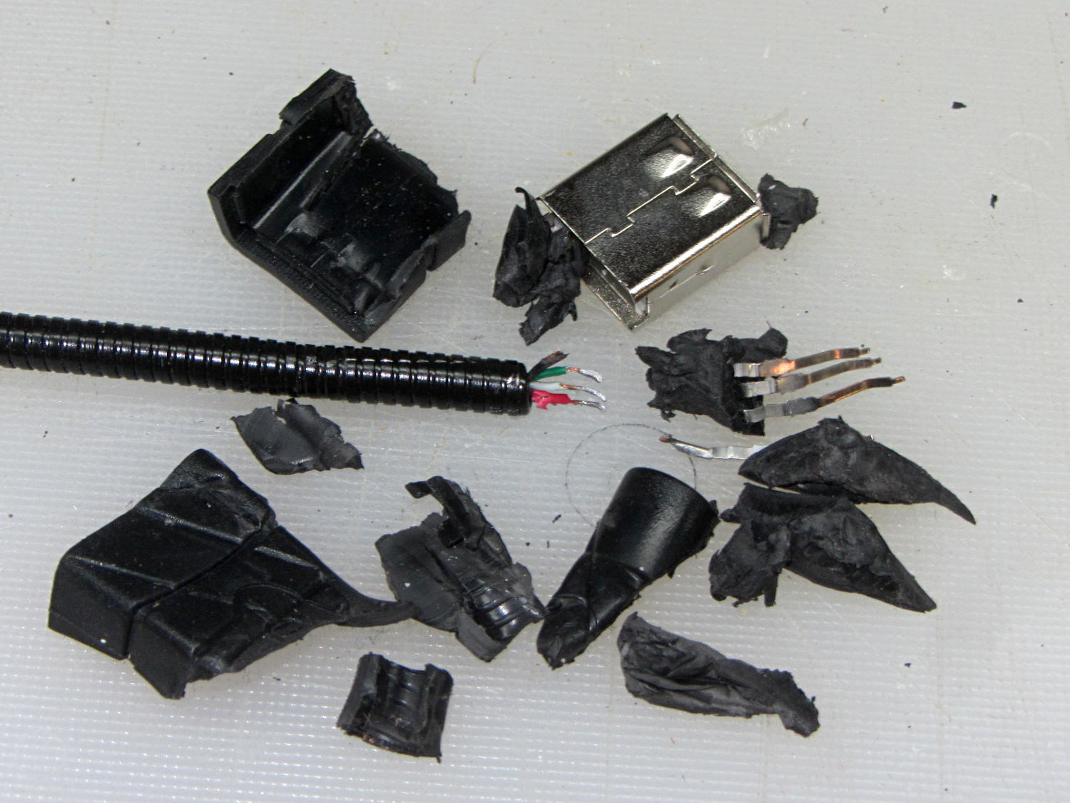
The bandsaw needs more light on the blade, but a fixed lamp will certainly get in the way of something. Pondering the solution space of available parts suggests a COB LED on a flexible gooseneck, which led to some 30 cm USB extenders, then smashing one of the connectors to reveal the wiring inside:
USB Gooseneck Extender – disassembled
It was (probably) assembled by soldering the USB terminals to the wires, mounting it in a fixture, then injection-molding the shell around everything. The injected plastic fills the end of the gooseneck and immobilizes the wires.
I’d like slightly longer wire ends, although they’re workable if I don’t make any further mistakes. Perhaps I can heatsink the gooseneck, slit 10 mm of the metal sheath with an abrasive wheel, and peel off the pieces without damaging the wires. It could happen!
Speaking of mistakes, wiring an ordinary USB connector with +12 VDC for an LED seems fraught with peril…
One might be forgiven for thinking these two USB Wifi adapters are essentially identical:
USB Wifi adapters
Turns out the SunFounder RT5370 (on the top, with the stylin’ curved case) has better performance than the Wifi With Antenna (on the bottom, with full-frontal chunk goin’ on), by a not inconsiderable 5 to 10 dB. Boosting the received power level in the fringe areas of our house from -70 dBm to -63 dBm makes all the difference between not working and steady streaming.
The built-in WiFi antenna on a Raspberry Pi 3 ticks along 10 dB lower, with -80 dBm (10 pW!) at the receiver making for poor communication: a Pi 3 works perfectly within reasonable line-of-sight of the router (even through our wood floor) and wakes up blind in fringe areas. Hacking an external antenna probably helps, but definitely isn’t a net win compared to ten bucks worth of USB adapter.
The wavemon utility (it’s in the Raspbian repo) comes in handy for figuring that sort of thing.
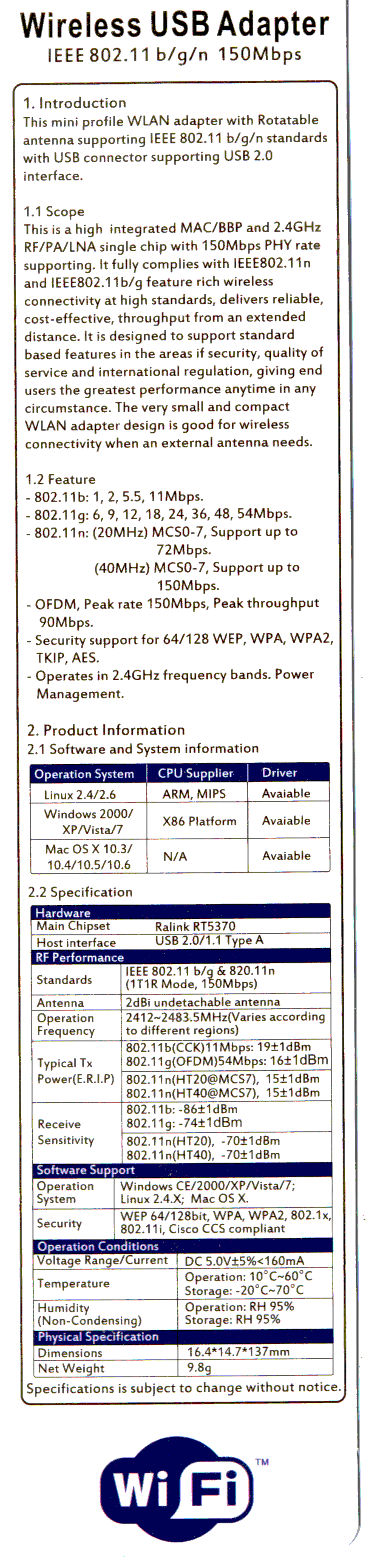
There is, of course, no way to determine anything important about the adapters from their product descriptions, which are essentially identical, right down to the price. Neither have any product identification on their cases. The back of the package for the SunFounder gadget gives some specs, none of which may mean anything (clicky for more dots):
SunFounder RT5370 USB WiFi Adapter Specs
I ordered another SunFounder adapter, Just In Case it comes in handy, with the hope that both behave the same way.
The (relatively) new Raspberry Pi 3 PCB layout puts the Run header in a different location than in the Pi 2, but a minute of filing gnaws a suitable opening:
Raspberry Pi 3 – Reset Switch
As before, a hot-melt glue blob holds the switch in place. I’d prefer a black case, if only to hide the blob, but clear-ish is what’s available right now.
Remember those orderly shutdowns, even at the cost of a keypad button!
The Dell AC511 USB SoundBars have volume control knobs, which this udev rule turns into the /dev/input/volume device:
ATTRS{name}=="Dell Dell AC511 USB SoundBar", SYMLINK+="input/volume"
I recently wanted to use an ordinary USB “sound card” that did not, of course, have a volume knob:
Sabrent USB Audio Adapter
This hack skips the configuration that makes the knob’s events visible to the Python program:
import os.path

... snippage ...

# if volume control knob exists, then set up its events

VolumeDevice = '/dev/input/volume'

vp = select.poll()
if os.path.exists(VolumeDevice):
  v = InputDevice(VolumeDevice)
  v.grab()
  vp.register(v.fileno(),select.POLLIN + select.POLLPRI + select.POLLERR)
It turns out that if you never register a device with the event polling interface, then the interface never reports any events and the rest of the code remains blissfully undisturbed: the non-existent knob doesn’t do anything, while the volume control buttons on the keypad continue to function as usual.
The end result of this fiddling puts a Raspberry Pi 2 Model B to work as a streaming player on my Electronics Workbench, untethering the laptop from those powered speakers:
RPi 2 Streaming Player – USB sound gadget
It’s a shame that USB audio gadget is so big, because it crowds out standard USB plugs to the side.
The most satisfactory LED configuration for a translucent case with an external WiFi adapter seems to be:
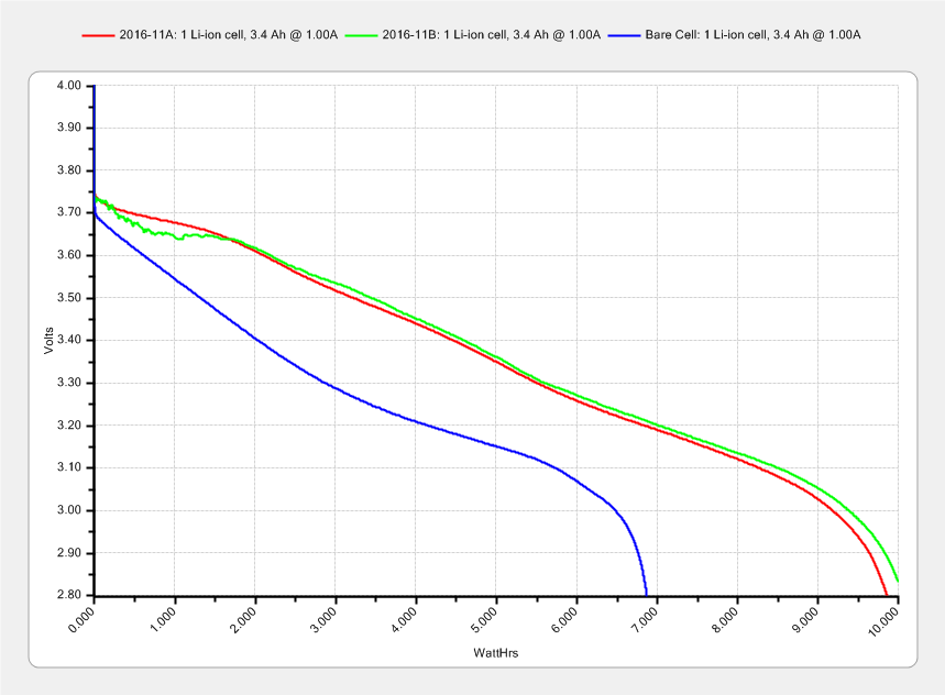
The lower curve comes from an old unprotected cell harvested from a defunct media player and retrieved from the to-be-recycled pile.
I picked 1 A as a reasonable value for their intended use in flashlights and maybe a helmet camera. Unlike some other cells in the recent past, these deliver 3.0 A·h, reasonably close to their rated 3.4 A·h capacity at a (presumably) lower current.
Replotting the voltage vs. energy delivered doesn’t show any surprises:
The voltage declines more-or-less linearly, without the relatively flat discharge curve for smaller cells, which explains why the J5 V2 flashlight becomes seriously dim after a few hours. On the upside, that allows a reasonably accurate state-of-charge display.
Assuming the Sony HDR-AS30V camera burns 0.1 W·h/min while recording (which is a fancy way of saying it dissipates 6 W), then it should run for (10 W·h)/(0.1W·h/min) = 100 min from one of these cells fitted as an outrigger. The best of the NP-BX1 cells for the camera delivers something like 90 minutes from a measured capacity of 4 A·h at 500 mA; I don’t know what to make of those numbers. Perhaps the camera runs the NP-BX1 cells below the 2.8 V cutoff I’ve been assuming?
The power switch in my trusty Fordham FG-801 Function Generator failed with an accumulation of oxidation / crud on the contacts. That’s fix-able, but the switch contained not one, but two powerful springs, and puked its guts all over the floor around the Squidwrench Operating Table. Even with (a preponderance of) the parts in hand, I couldn’t figure out how to reassemble the thing; the only way out was to replace the switch.
The OEM switch had a 0.360+ inch diameter pushbutton that fit into a ⅜ inch hole and, alas, my remaining stock of line-voltage switches had toggle levers and used ¼ inch holes. So I converted a bit of aluminum rod into a suitable bushing:
Fordham FG-801 Fn Gen – new switch hardware
The lock washer in the middle started with a much wider tab that I filed down into a tooth for the dent from a #2 center drill. Protip: center drills don’t walk off like twist drills, even when you hand-hold the front panel at the drill press with all the electronics dangling below.
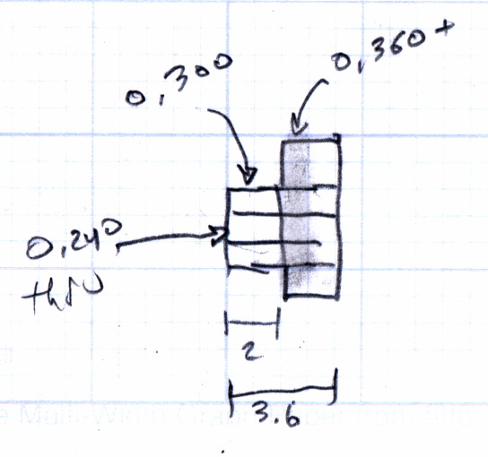
The bushing dimension doodle:
Fordham FG-801 Function Generator – Replacement Switch Bushing
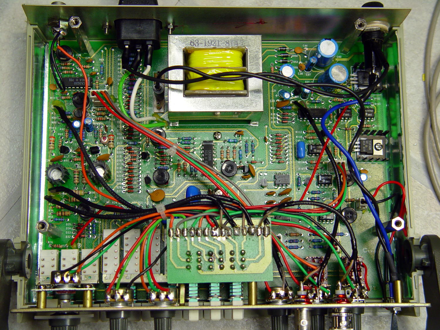
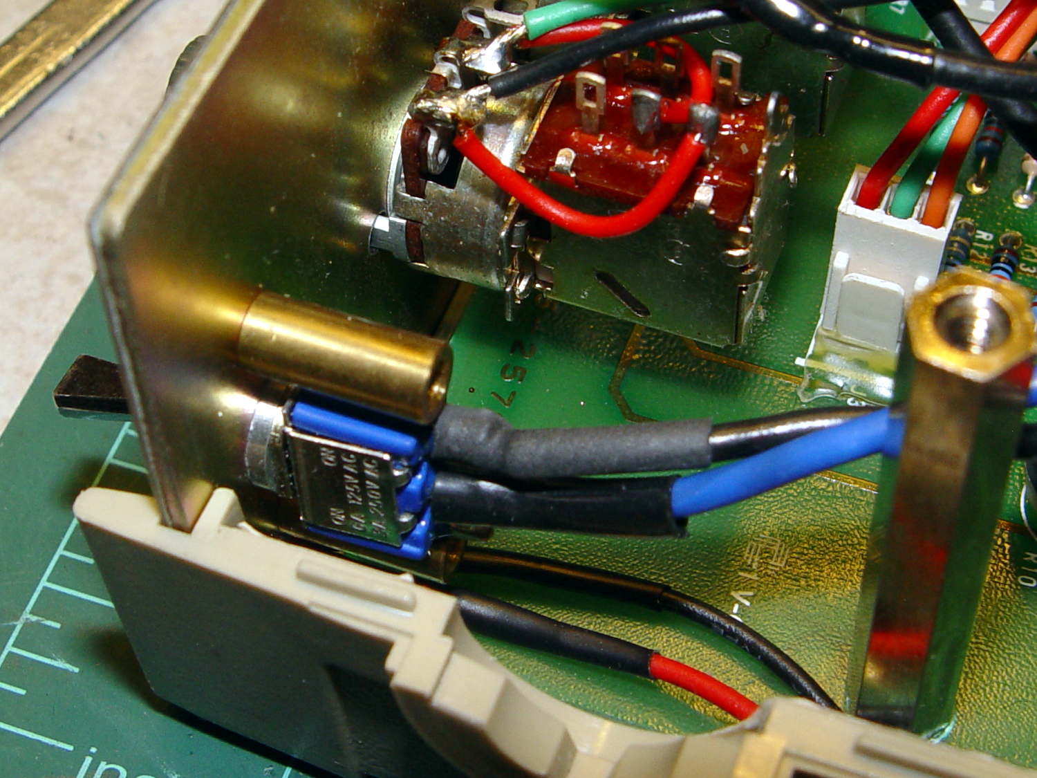
The internal wiring routes the 120 VAC line conductor to the switch, then to the fuse, then to the transformer. I don’t know whether it’s better to have an unfused switch or an unswitched fuse (surely there’s a UL spec for that), but I didn’t change anything. The new switch, being slightly smaller and mounting directly on the panel, required a new wire (the blue one) from the fuse:
Fordham FG-801 Fn Gen – power switch – installed
The OEM switch mounted on two round brass standoffs and, wonder to tell, the new switch fit between them!
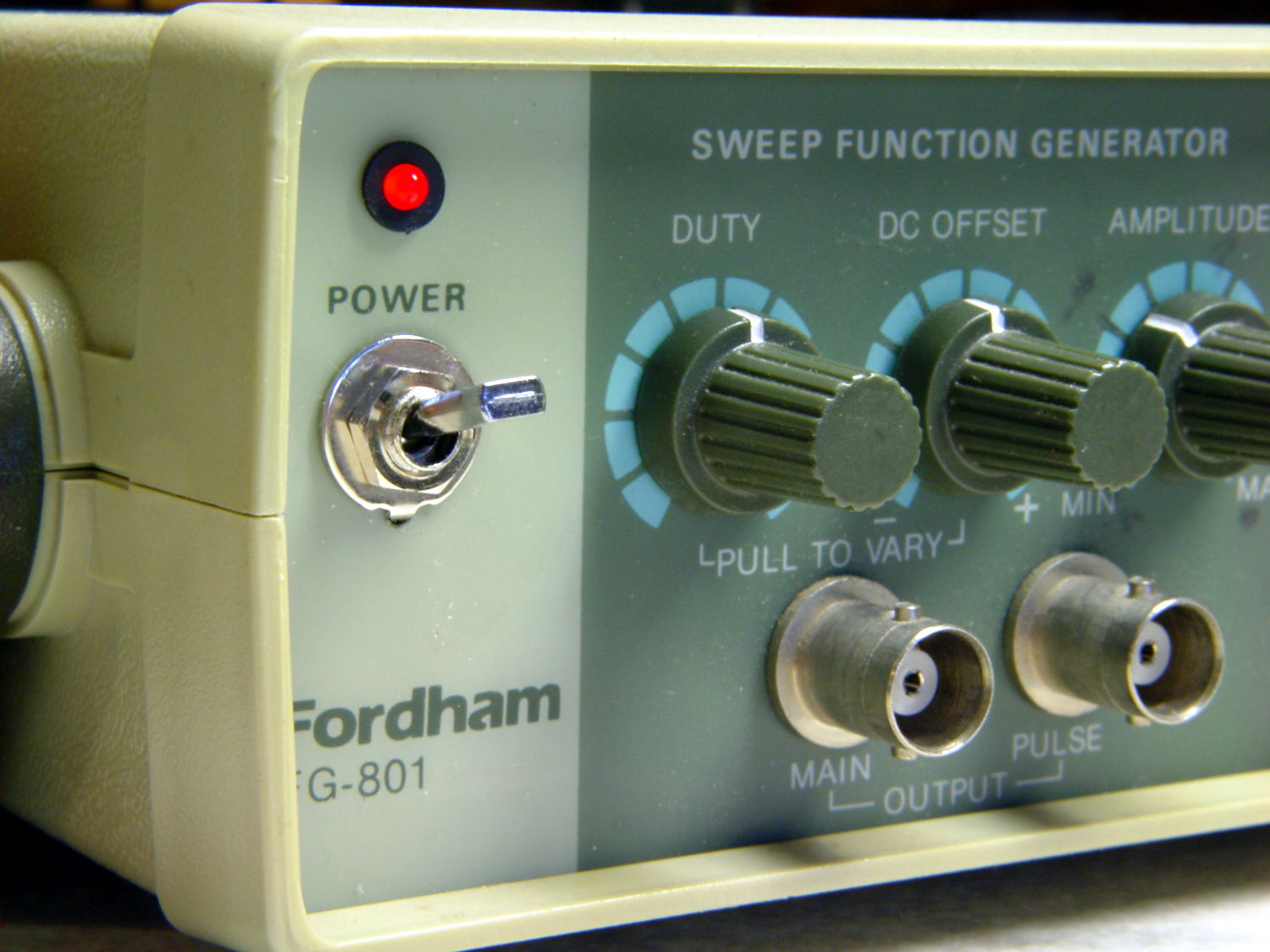
From the front, the new switch looks like it grew there:
Fordham FG-801 Fn Gen – switch in action
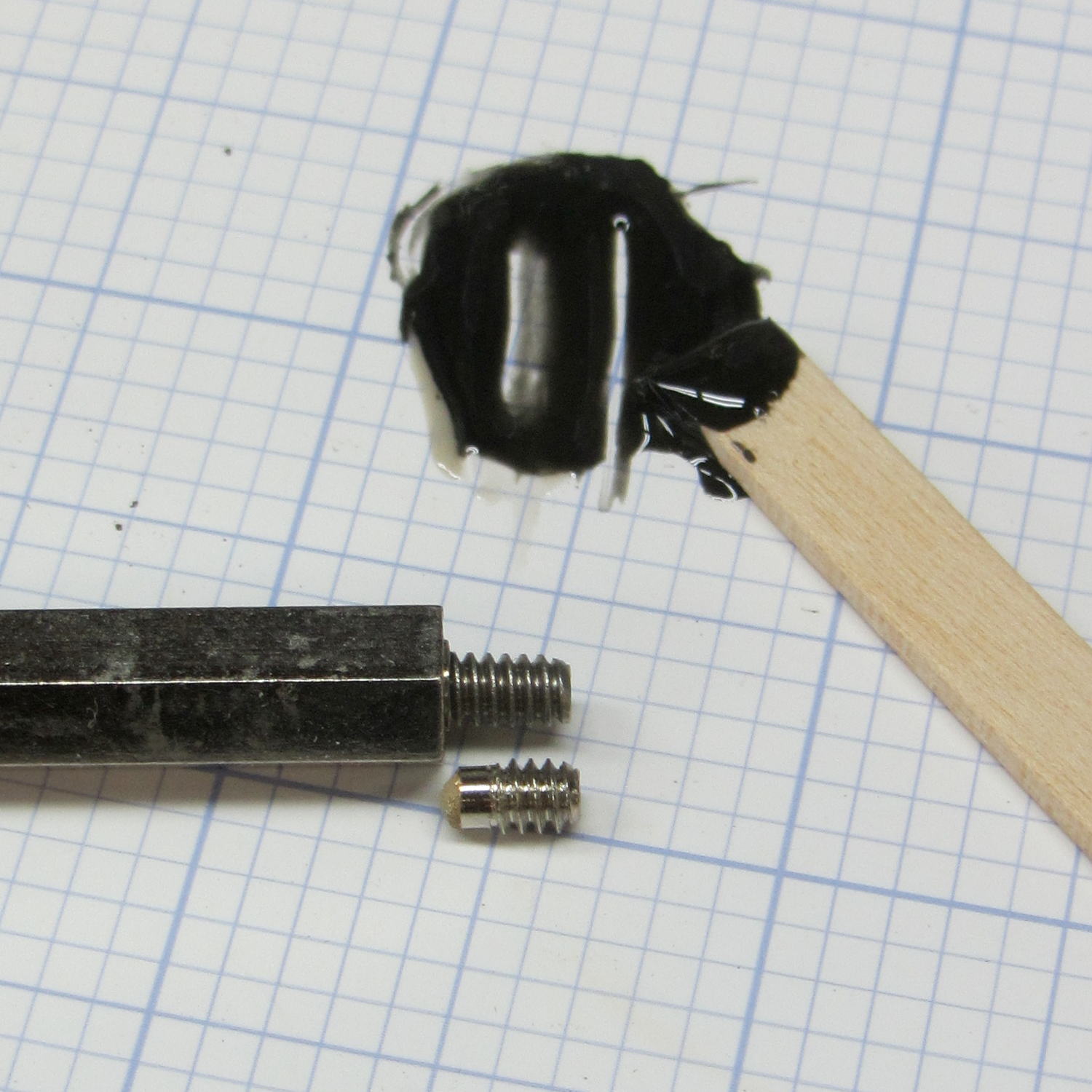
The PCB mounts to the top of the case with one screw and four hexagonal brass standoffs. The standoffs have 6-32 tapped holes on one end and a 6-32 stud on the other; one of those stud had broken off. A 6-32 stainless steel screw secured in a clearance hole with a dab of epoxy solved that problem:
Fordham FG-801 Fn Gen – standoff stud
I stood it vertically and tweaked the screw to be perpendicular while the epoxy cured.
Memo to Self: The next time around, put a nut on the stud to make sure the answer comes out right. I didn’t do this time to avoid epoxying the nut to the standoff.