Ed Nisley's Blog: Shop notes, electronics, firmware, machinery, 3D printing, laser cuttery, and curiosities. Contents: 100% human thinking, 0% AI slop.
My pocket camera has begun kvetching about a low battery rather more often than before, which suggests the batteries I’ve been using since 2014 have gone beyond their best-used-by date.
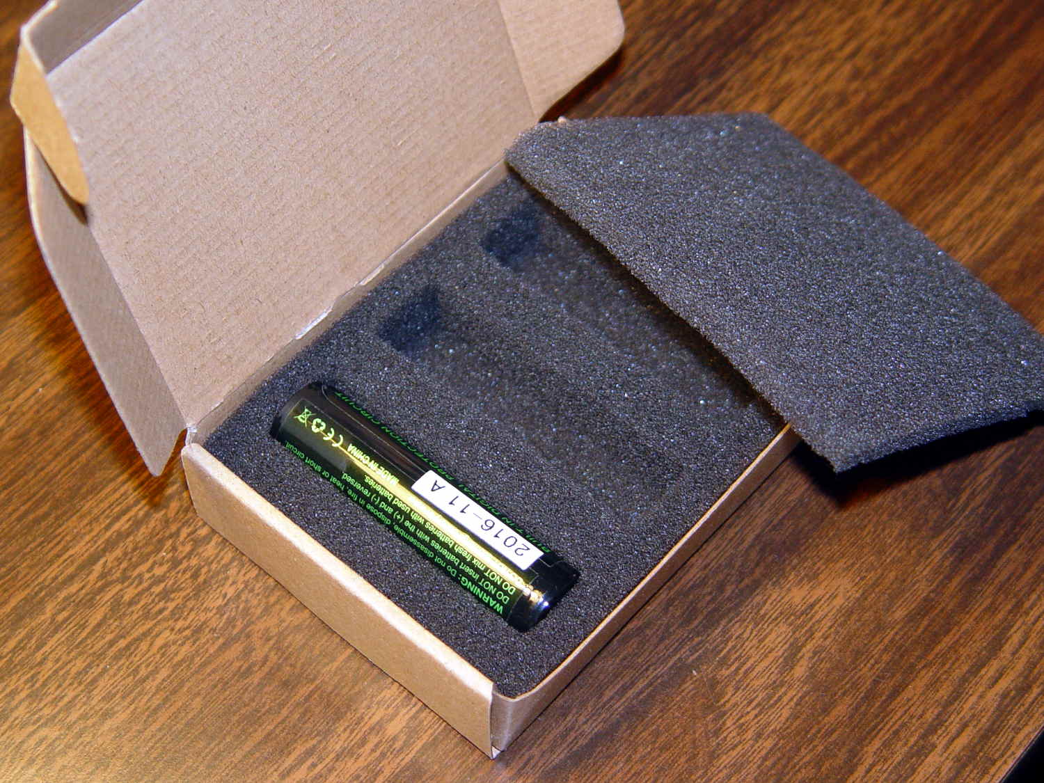
This came as no surprise:
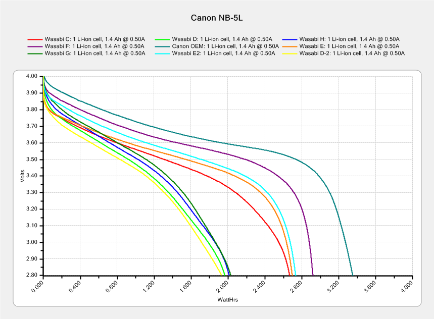
Canon NB-5L – 2017-08-05
I re-ran a couple of the batteries to make sure they hadn’t faded away from disuse, which didn’t materially change the results. The lightly used Canon OEM battery continues to lead the, ah, pack.
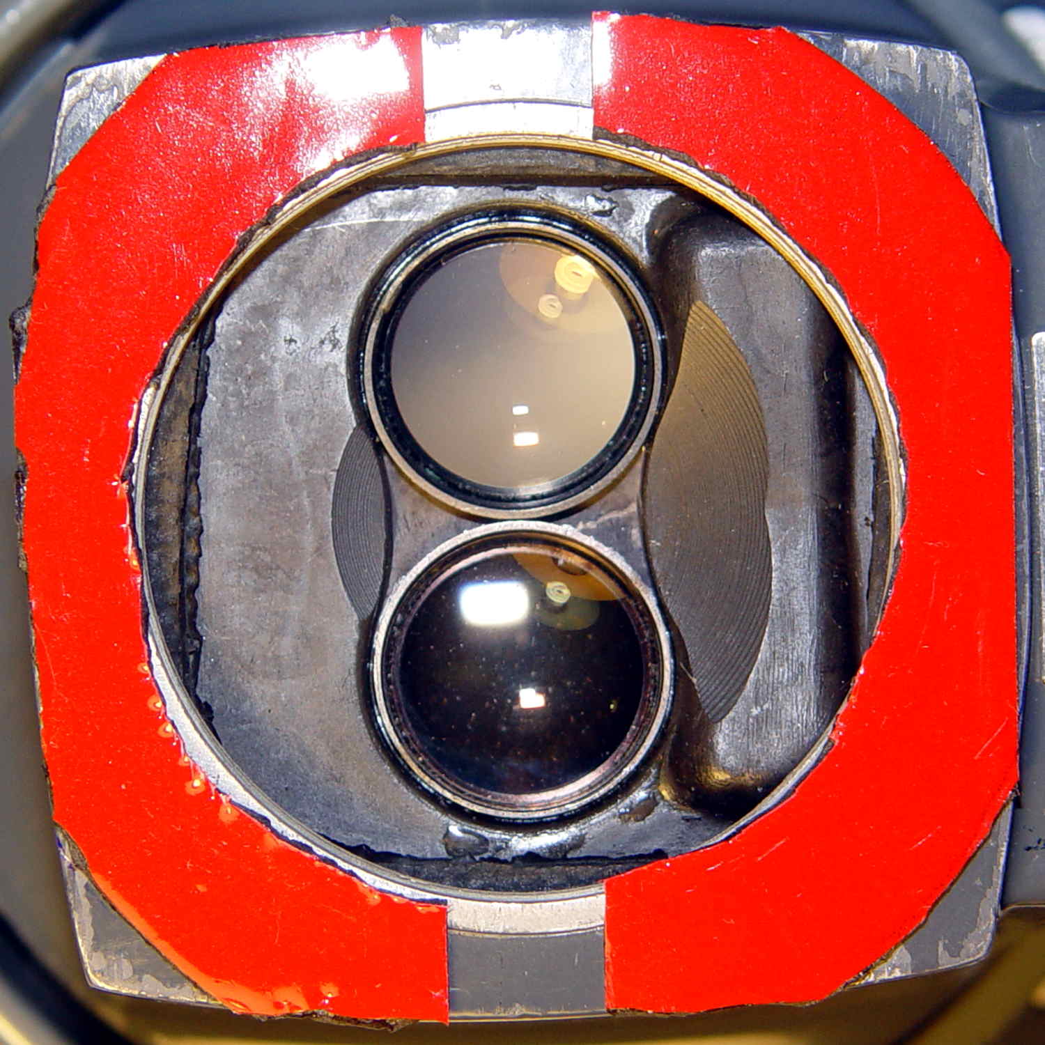
The camera’s lens capsule accumulated a fair bit of dust from many years in my pocket, which lowers its overall contrast and wrecks the high f/ images produced with the microscope adapter.
Isolating the USB port from the laptop eliminated a nasty ground loop, turning off the OLED while making measurements stifled a huge noise source, and averaging a few ADC readings produced this pleasing plot:
Resonator 0 Spectrum
Those nice smooth curves suggest the tester isn’t just measuring random junk.
The OLED summarizes the results after the test sequence:
LF Crystal Tester – OLED test summary – Resonator 0
Collecting all the numbers for that resonator in one place:
I ripped that nice layout directly from my November Circuit Cellar column, because I’m absolutely not even going to try to recreate those equations here.
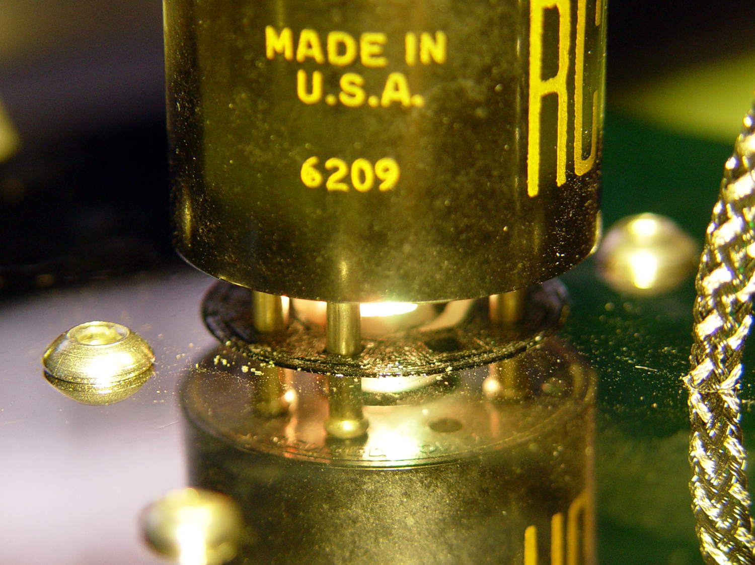
The tiny lip holding the new LED ring light into the microscope snout lacked enough traction and deposited the ring light on the desk. Having picked up a roll of Scotch Extreme Mounting Tape to see how well it works to attach LEDs to vacuum tubes, I’ll see how well it affixes a ring light to a microscope:
Stereo zoom microscope – taped snout
The red plastic film separates the tape layers on the spool; the tape itself consists of incredibly sticky, gooey adhesive on a very flexible foam backing. As you can tell from the ragged edges, cutting it requires some effort, with the adhesive instantly gumming up scissors. I applied a razor knife around the microscope snout’s perimeter, pressing from the red film side and pulling the cut sections apart as I went.
The adhesive exposed on the edges of the roll will glue it to anything it touches, so hang up the roll. Laying it on a shelf will definitely cause heartache & confusion.
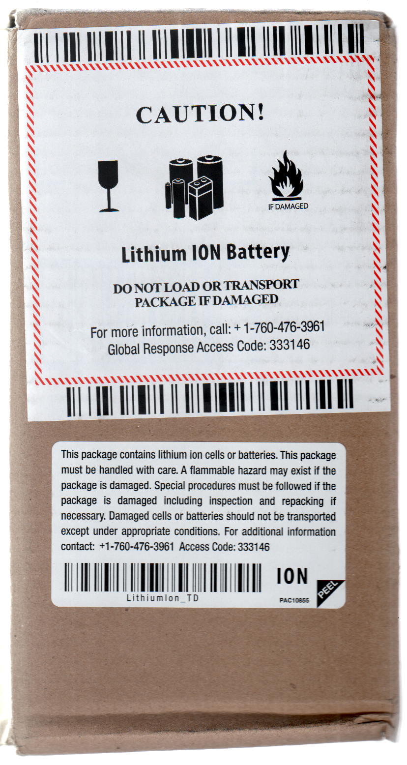
The instructions on the back label suggest 2 square inches of tape will hold 1 pound:
Scotch Extreme Mounting Tape – label
Given that the ring light weighs a few ounces, tops, those two strips should do fine.
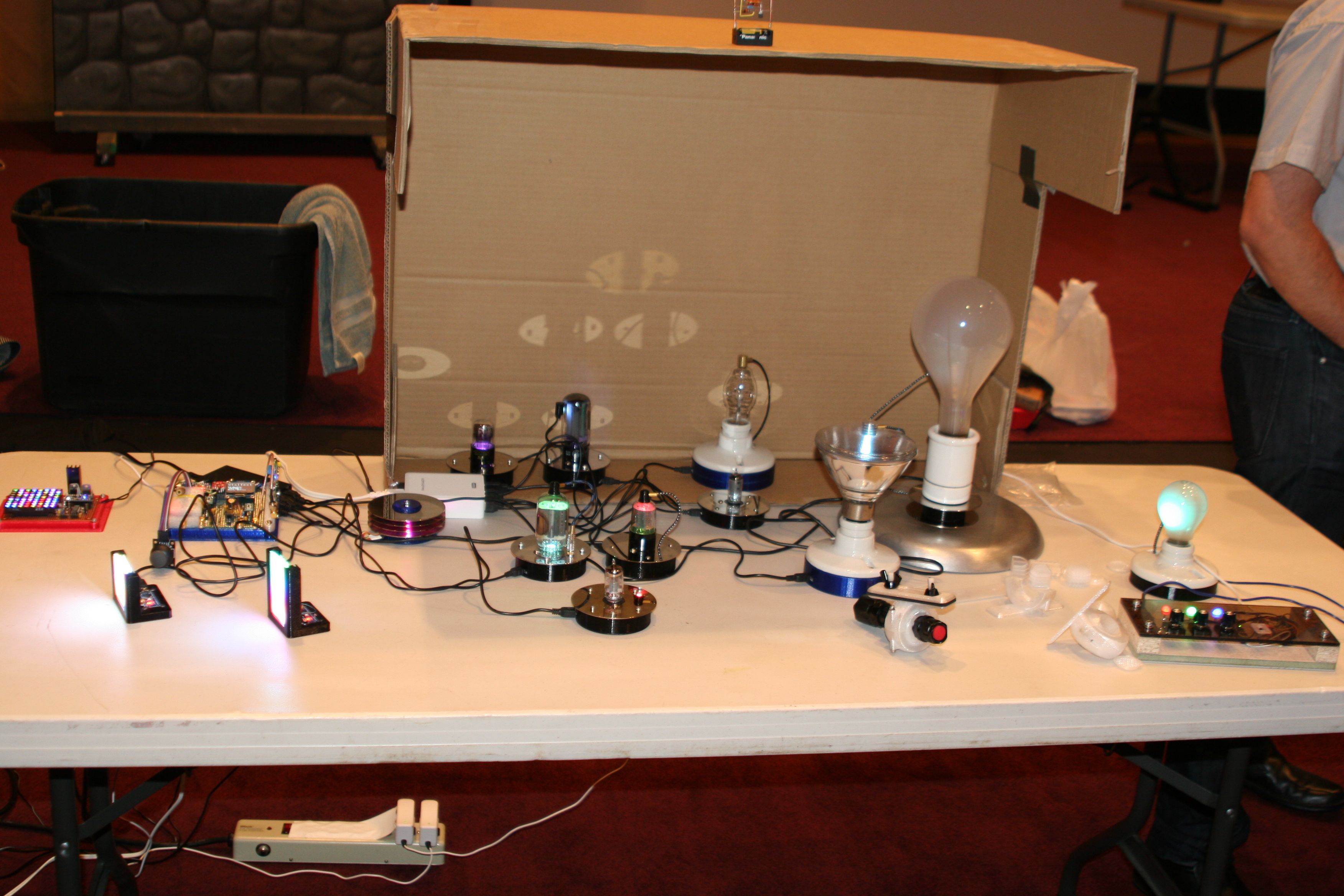
They look much better without a flash, honest. The cut-up cardboard box threw much needed shade; the auditorium has big incandescent can lights directly overhead.
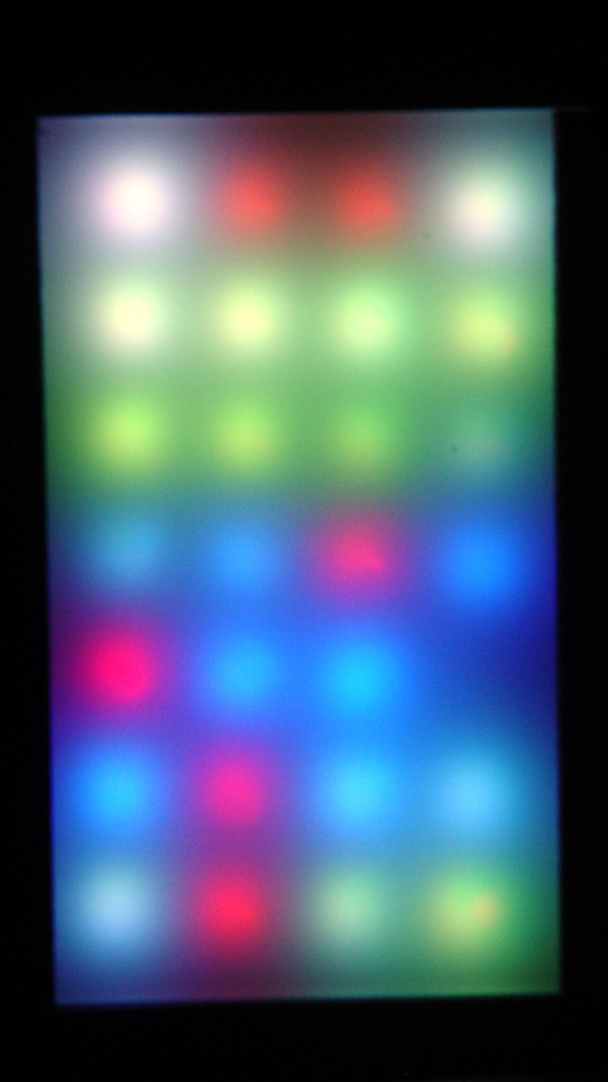
Anyhow, what with one thing and another, the two LED test fixtures spent another few dark and cool days in the Basement Laboratory. When I finally plugged them in, the SK6812 RGBW LED array light up just fine, but three more WS2812 RGB LEDs went toes-up:
WS2812 LED test fixture – more failures
That brought the total to about 8 (one looks like it’s working) out of 28: call it a 28% failure rate. While WS2812 LEDs don’t offer much in the way of reliability, running them continuously seems to minimize the carnage.
So I wired around the new deaders and took that picture.
Flushed with success and anxious to get this over with, I sealed the tester in a plastic bag and tossed it in the freezer for a few hours …
Which promptly killed most of the remaining WS2812 chips, to the extent even a protracted session on the Squidwrench Operating Table couldn’t fix it. When I though I had all the deaders bypassed, an LED early in the string would wig out and flip the panel back to pinball panic mode.
It’s not a 100% failure rate, but close enough: they’re dead to me.
As the remaining WS2812 LEDs on the various vacuum tubes and bulbs go bad, I’m replacing them with SK6812 RGBW LEDs.
For whatever it’s worth, freezing the SK6812 tester had no effect: all 25 LEDs lit up perfectly and run fine. Maybe some of those chips will die in a few days, but, to date, they’ve been utterly reliable.
The LEDs adorning the 0D3 rectifier tube became unreliable:
0D3 Octal – 25 mm socket – raised LED
After failing to plug in a different USB power supply, a close look at the USB connector showed the problem:
Knockoff Arduino Nano – broken Mini-B connector
A bit of needle-nosetweezering extracted the culprit from the power supply’s connector:
Knockoff Arduino Nano – broken Mini-B connector – fragment
I tried applying the world’s smallest dot of epoxy to the fracture, probably slobbered epoxy along the pins while reinserting it, and the Nano still doesn’t light up.
Given that knockoff Nano boards cost a touch over two bucks delivered, it’s not clear transplanting a connector from one of the never-sufficiently-to-be-damned counterfeit FTDI USB adapters makes any sense.