Ed Nisley's Blog: Shop notes, electronics, firmware, machinery, 3D printing, laser cuttery, and curiosities. Contents: 100% human thinking, 0% AI slop.
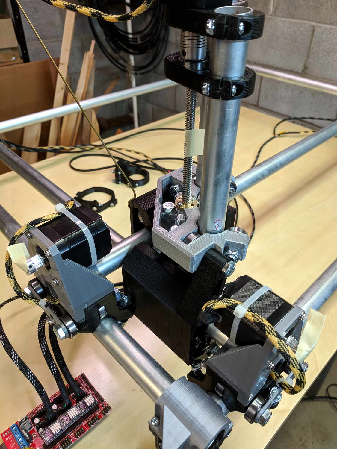
To the end of documenting colors, connectors, and connections for the MPCNC stepper motors …
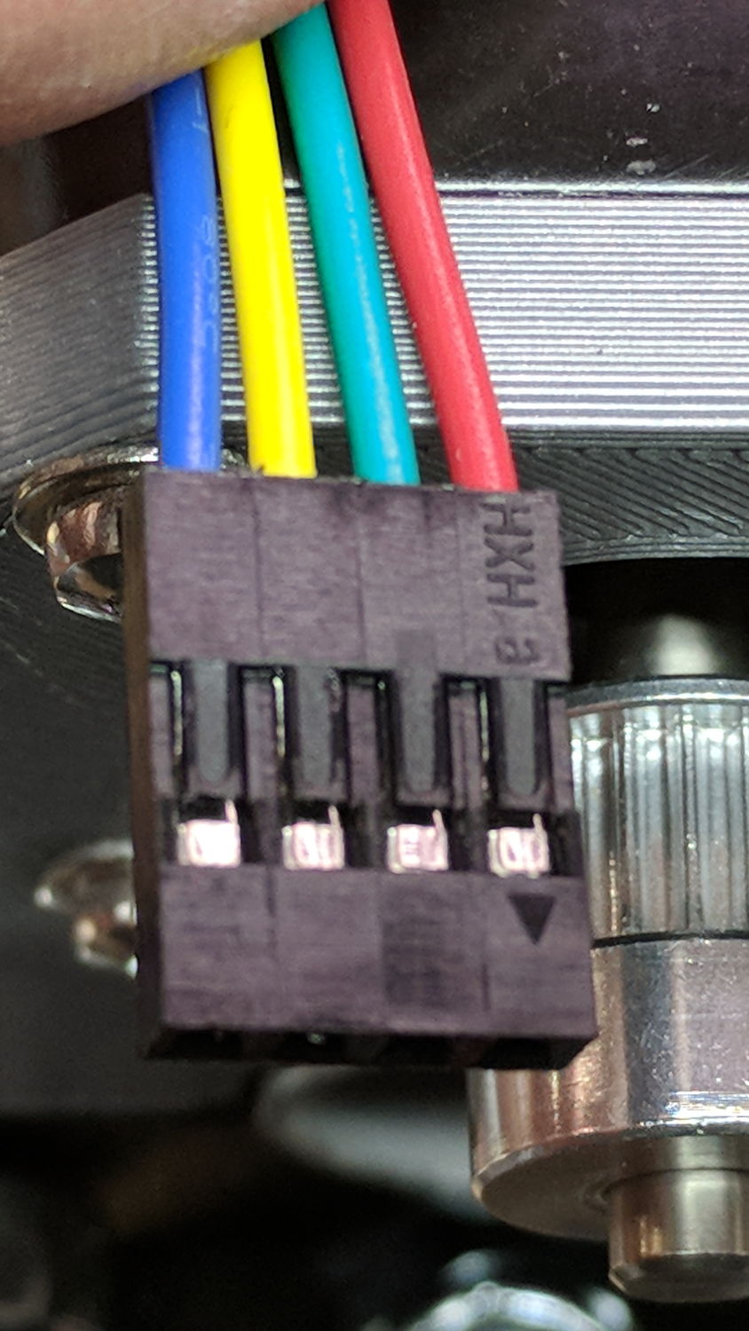
At the stepper motors:
MPCNC – Stepper Connector
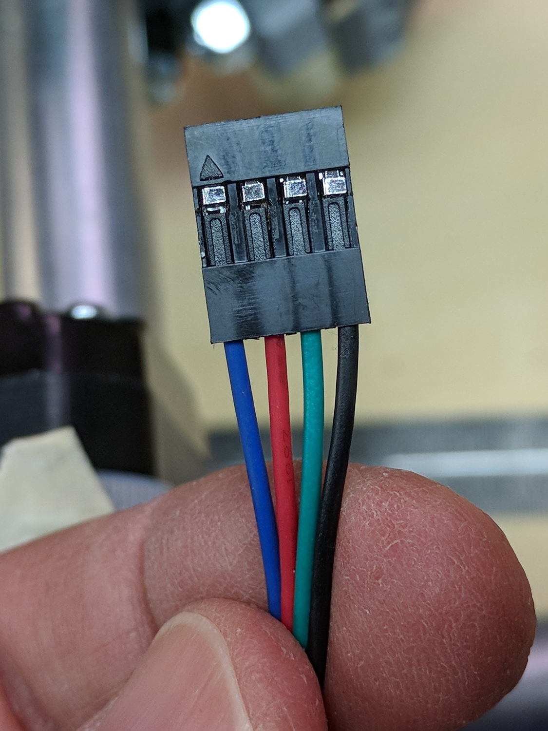
The plug for the stepper at the end of the harness:
MPCNC – Stepper Harness end connector
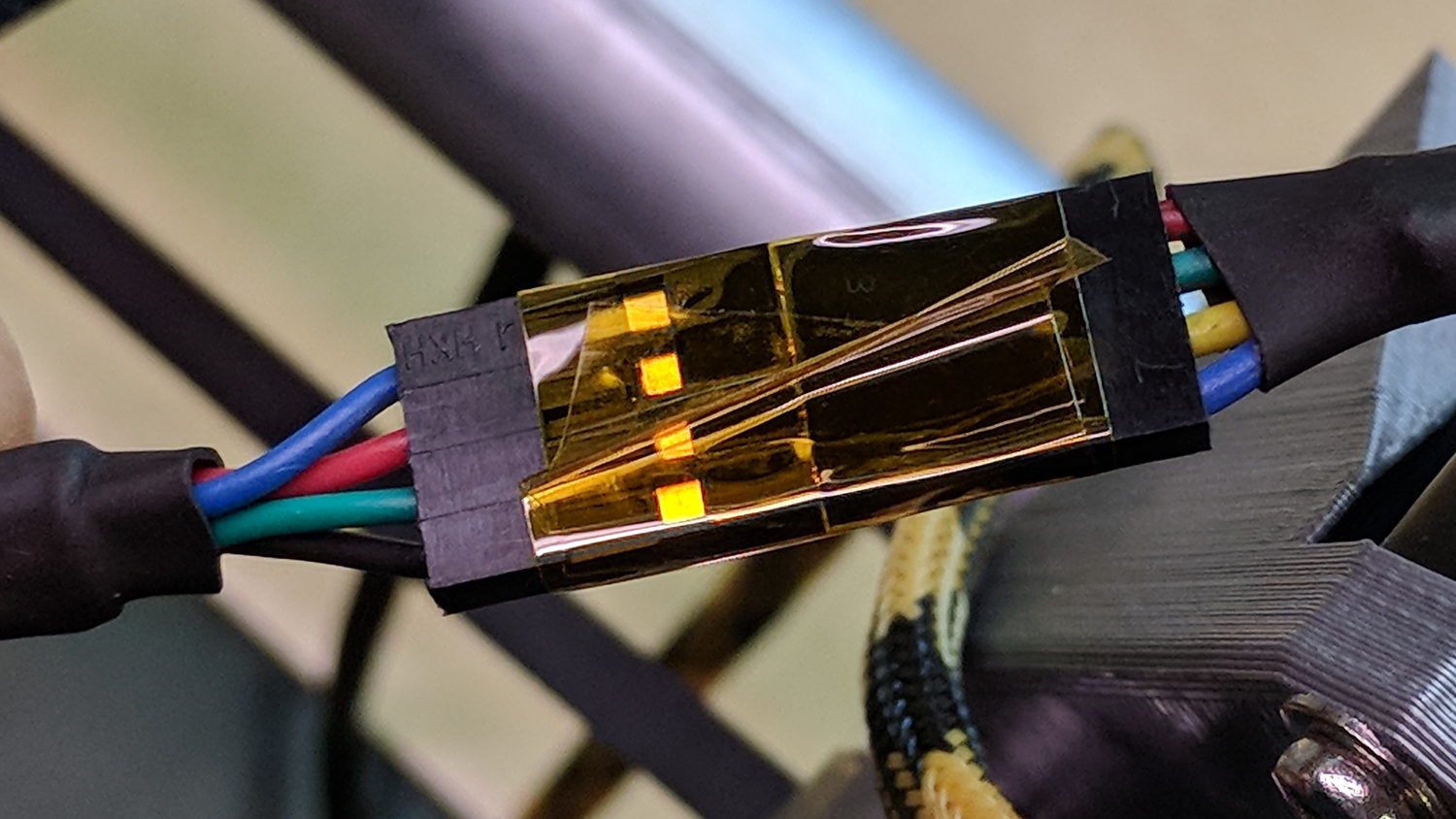
I opted to match the “pin 1” marks on the connectors, because that’s easy to remember, although it puts the pin latches on opposite sides:
MPCNC – Stepper to Harness End
Some obligatory Kapton tape holds the two connectors together.
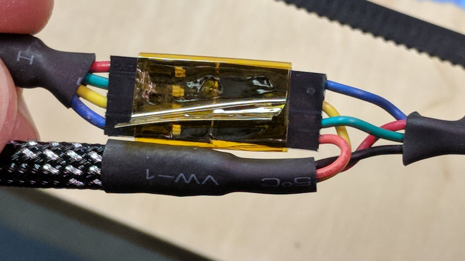
The joint at the middle of the harness, with the near-end stepper cable on the upper left:
MPCNC – Stepper Harness mid connection
At the RAMPS driver end of the cable:
MPCNC – Stepper harness – driver end
The Z-axis extension cable, with the stepper cable on the right:
MPCNC – Z stepper to extension cable
I plugged the cables into the RAMPS board with the “pin 1” mark at the A1A2 end of the connectors.
With all the wires in place (and the GT2 drive belt still in its bag), I stuck masking tape tabs on the motor shafts, connected the RAMPS board, and verified the directions:
MPCNC – Stepper motor direction test
Although the Y axis needed reversing, both pairs of motors turned in the same direction!
Being that type of guy, I reversed the Y axis direction in the firmware configuration, because it’s easier for me to make all the physical connections look the same than (try to) remember to flip the Y axis connector whenever I must reconnect the cable to the driver.
A reader (you know who you are!) proposed an interesting project that will involve measuring audio passbands and suggested using white noise to show the entire shape on a spectrum analyzer. He pointed me at the NOISE 1B Noise Generator based on a PIC microcontroller, which led to trying out the same idea on an Arduino.
The first pass used the low bit from the Arduino runtime’s built-in random() function:
Arduino random function bit timing
Well, that’s a tad pokey for audio: 54 μs/bit = 18.5 kHz. Turns out they use an algorithm based on multiplication and division to produce nice-looking numbers, but doing that to 32 bit quantities takes quite a while on an 8 bit microcontroller teleported from the mid 1990s.
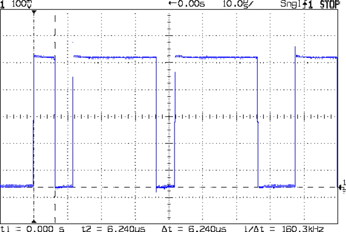
The general idea is to send a bit from the end of a linear feedback shift register to an output to produce arandomly switching binary signal. Because successive values involve only shifts and XORs, it should trundle along at a pretty good clip and, indeed, it does:
Arduino Galois shift reg bit timing
I used the Galois optimization, rather than a traditional LFSR, because I only need one random bit and don’t care about the actual sequence of values. In round numbers, it spits out bits an order of magnitude faster at 6 μs/bit = 160 kHz.
The spectrum looks pretty good, particularly if you’re only interested in the audio range way over on the left side:
Arduino Galois bit spectrum
It’s down 3 dB at 76 kHz, about half the 160 kHz bit flipping pace.
If you were fussy, you’d turn off the 1 ms timer interrupt to remove a slight jitter in the output.
It’s built with an old Arduino Pro Mini wired up to a counterfeit FTDI USB converter. Maybe this is the best thing I can do with it: put it in a box with a few audio filters for various noise colors and be done with it.
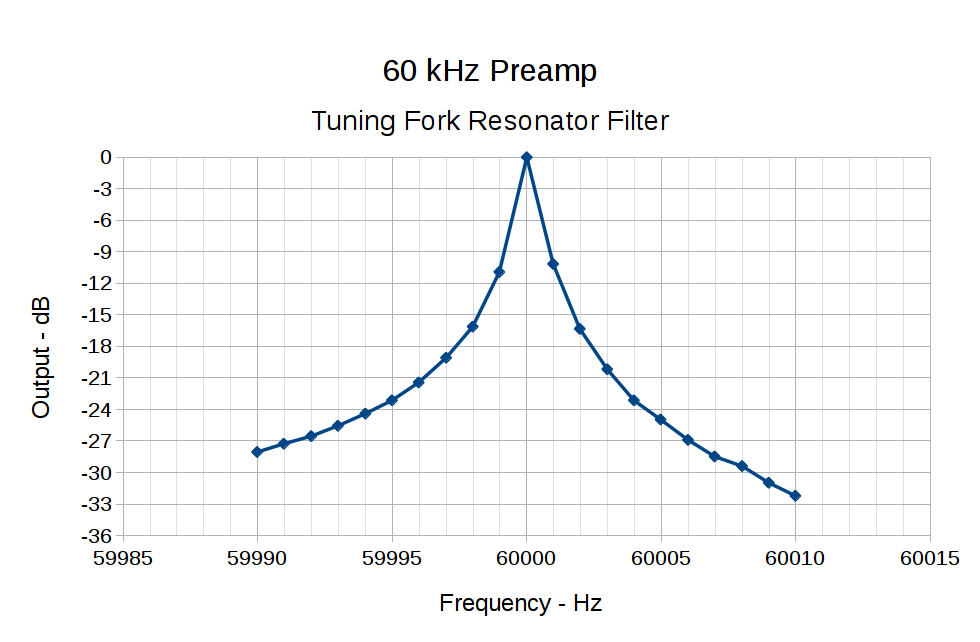
It occurs to me I could fire it into the 60 kHz preamp’s snout to measure the response over a fairly broad range while I’m waiting for better RF reception across the continent.
This file contains hidden or bidirectional Unicode text that may be interpreted or compiled differently than what appears below. To review, open the file in an editor that reveals hidden Unicode characters.
Learn more about bidirectional Unicode characters
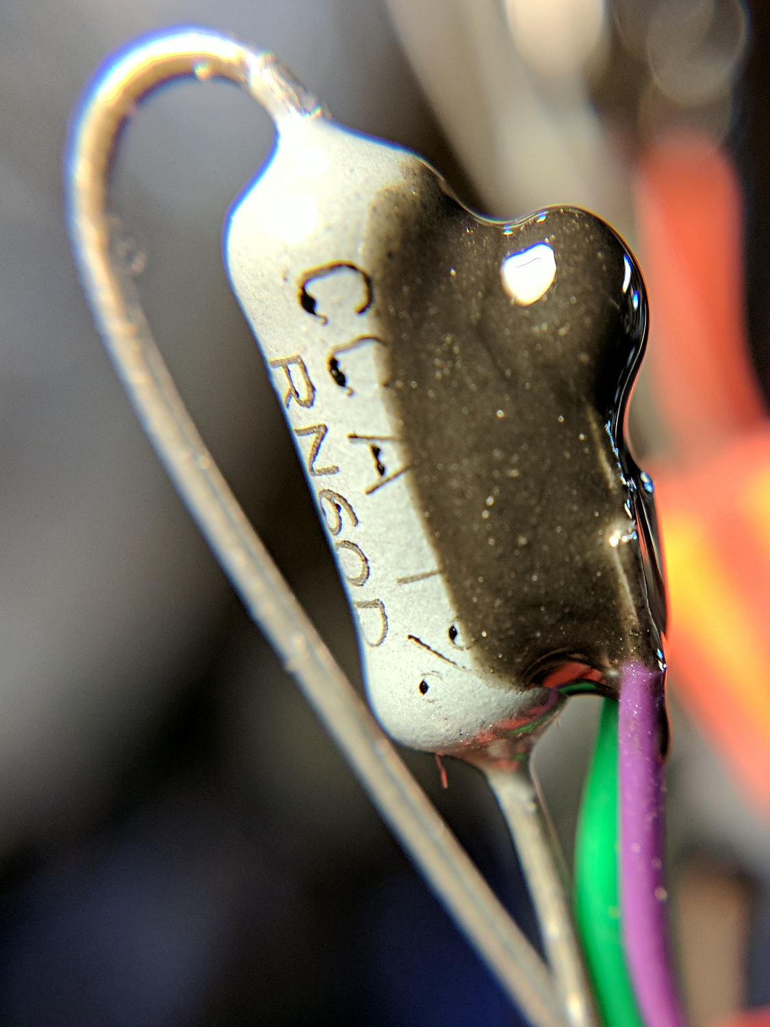
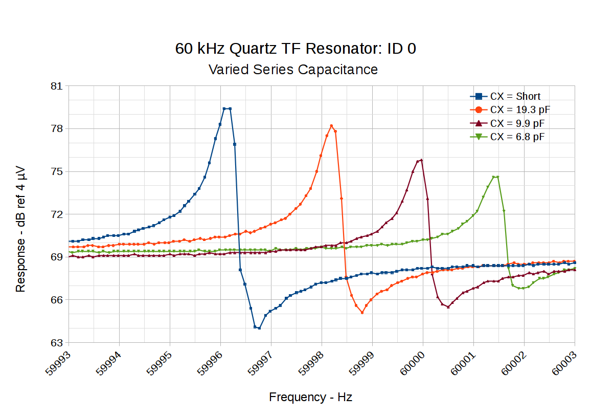
Putting a small capacitor in series with the tuning fork resonator pulls the series resonant frequency upward and reduces the amplitude:
60 kHz Quartz TF Resonator – CX variations
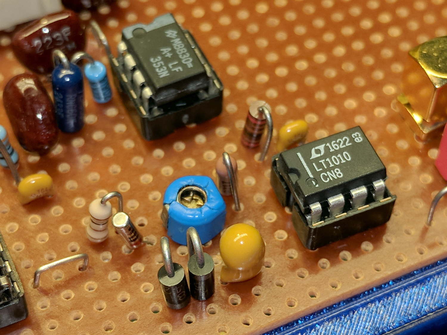
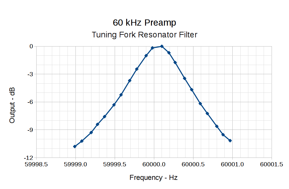
So something around 10 pF, net of stray capacitance and suchlike, should suffice. Plunk a small twiddlecap on the preamp board and tune for best picture:
While contemplating all the hocus-pocus and precision alignment involved in the DIY plotter project, it occurred to me you could conjure a plotter from a pair of steppers, two disks, a lifting mechanism, and not much else. The general idea resembles an Rθ plotter, with the paper glued to a turntable for the “theta” motion, but with the “radius” motion produced by pen(s) on another turntable:
Rotary Plotter – geometry 4
The big circle is the turntable with radius R1, which might be a touch over 4.5 inches to fit an 8.5 inch octagon cut from ordinary Letter paper. The arc with radius R2 over on the right shows the pen path from the turntable’s center to its perimeter, centered at (R1/2,-R1) for convenience.
The grid paper represents the overall Cartesian grid containing the XY points you’d like to plot, like, for example, point Pxy in the upper right corner. The object of the game is to figure out how to rotate the turntable and pen holder to put Pxy directly under the pen at Ixy over near the right side, after which one might make a dot by lowering the pen. Drawing a continuous figure requires making very small motions between closely spaced points, using something like Bresenham’s line algorithm to generate the incremental coordinates or, for parametric curves like the SuperFormula, choosing a small parameter step size.
The offset between the two centers is (ΔX,ΔY) and the distance is R2 = sqrt(ΔX² + ΔY²). The angle between the +X axis and the pen wheel is α = atan2(ΔY,ΔX), which will be negative for this layout.
Start by transforming Pxy to polar coordinates PRθ, which produces the circle containing both Pxy and Ixy. A pen positioned at radius R from the center of the turntable will trace that circle and Ixy sits at the intersection of that circle with the pen rotating around its wheel.
The small rectangle with sides a and b has R as its diagonal, which means a² + b² = R² and the pointy angle γ = atan a/b.
The large triangle below that has base (R2 – a), height b, and hypotenuse R2, so (R2 – a)² + b² = R2².
Some plug-and-chug action produces a quadratic equation that you can solve for a as shown, solve for b using the first equation, find γ from atan a/b, then subtract γ from θ to get β, the angle spearing point Ixy. You can convert Rβ back to the original grid coordinates with the usual x = R cos β and y = R sin β.
Rotate the turntable by (θ – β) to put Pxy on the arc of the pen at Ixy.
The angle δ lies between the center-to-center line and Ixy. Knowing all the sides of that triangle, find δ = arccos (R2 – a) / R2 and turn the pen wheel by δ to put the pen at Ixy.
Lower the pen to make a dot.
Done!
Some marginal thinking …
I’m sure there’s a fancy way to do this with, surely, matrices or quaternions, but I can handle trig.
You could drive the steppers with a Marlin / RAMPS controller mapping between angles and linear G-Code coordinates, perhaps by choosing suitable steps-per-unit values to make the degrees (or some convenient decimal multiple / fraction thereof)correspond directly to linear distances.
You could generate points from an equation in, say, Python on a Raspberry Pi, apply all the transformations, convert the angles to G-Code, and fire them at a Marlin controller over USB.
Applying 16:1 microstepping to a stock 200 step/rev motor gives 0.113°/step, so at a 5 inch radius each step covers 0.01 inch. However, not all microsteps are moved equally and I expect the absolute per-step accuracy would be somewhere between OK and marginal. Most likely, given the application, even marginal accuracy wouldn’t matter in the least.
The pen wheel uses only 60-ish degrees of the motor’s rotation, but you could mount four-ish pens around a complete wheel, apply suitable pen lift-and-lower action and get multicolor plots.
You could gear down the steppers to get more steps per turntable revolution and way more steps per pen arc, perhaps using cheap & readily available RepRap printer GT2 pulleys / belts / shafts / bearings from the usual eBay sellers. A 16 tooth motor pulley driving a 60 tooth turntable pulley would improve the resolution by a factor of 3.75: more microsteps per commanded motion should make the actual motion come out better.
Tucking the paper atop the turntable and under the pen wheel could be a challenge. Perhaps mounting the whole pen assembly on a tilting plate would help?
Make all the workings visible FTW!
Some doodles leading up to the top diagram, complete with Bad Ideas and goofs …
Centering the pen wheel at a corner makes R2 = R1 * sqrt(2), which seems attractive, but seems overly large in retrospect:
Rotary Plotter – geometry 1
Centering the pen wheel at (-R1,R1/2) with a radius of R1 obviously doesn’t work out, because the arc doesn’t reach the turntable pivot, so you can’t draw anything close to the center. At least I got to work out some step sizes.
A first attempt at coordinate transformation went nowhere:
Rotary Plotter – geometry 2
After perusing the geometric / triangle solution, this came closer:
When I plugged the LCD into the RAMPS board, the USB current jumped from 70-ish mA to about 700 mA, which seemed odd. Eventually the problem followed the “Smart Adapter Board”, which has no active components and simply rearranges two pin headers into two ribbon cables, so what could go wrong?
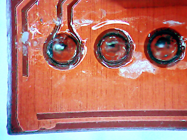
This stared me in the face for a while until I recognized it:
RAMPS 1.4 – Smart Adapter – solder mask failure
Yup, that trace is supposed to run around the corner without merging into the ground plane and, of course, it carries the +5 V power supply to the LCD board. Just another production goof and, I’m certain, the boards don’t get any testing because they’re so simple.
Two cuts, a bit of scraping, a snippet of Wire-Wrap wire, and it’s all good:
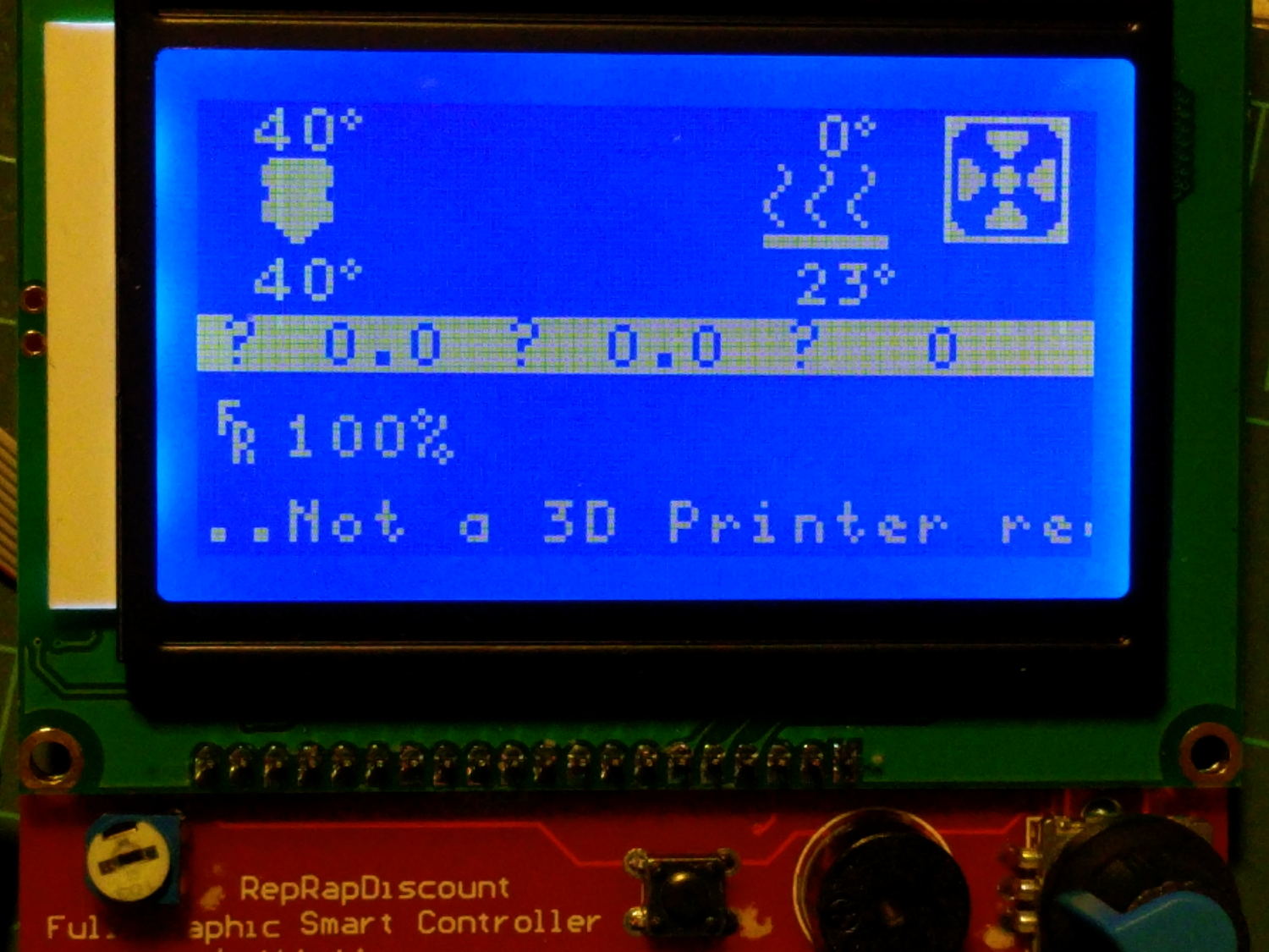
RAMPS 1.4 – LCD panel
The white-on-blue display is reasonably legible in person, even if it’s nearly invisible here. Might have something to do with polarization vs. the Pixel’s camera.
Everything else on the LCD board works fine. I set the beep to 50 ms and the tone to 700 Hz, which suit my deflicted ears better than the defaults.