Ed Nisley's Blog: Shop notes, electronics, firmware, machinery, 3D printing, laser cuttery, and curiosities. Contents: 100% human thinking, 0% AI slop.
The relay at the top connects the AC hot line to the rest of the circuitry, with a feeble red LED to show when it’s live:
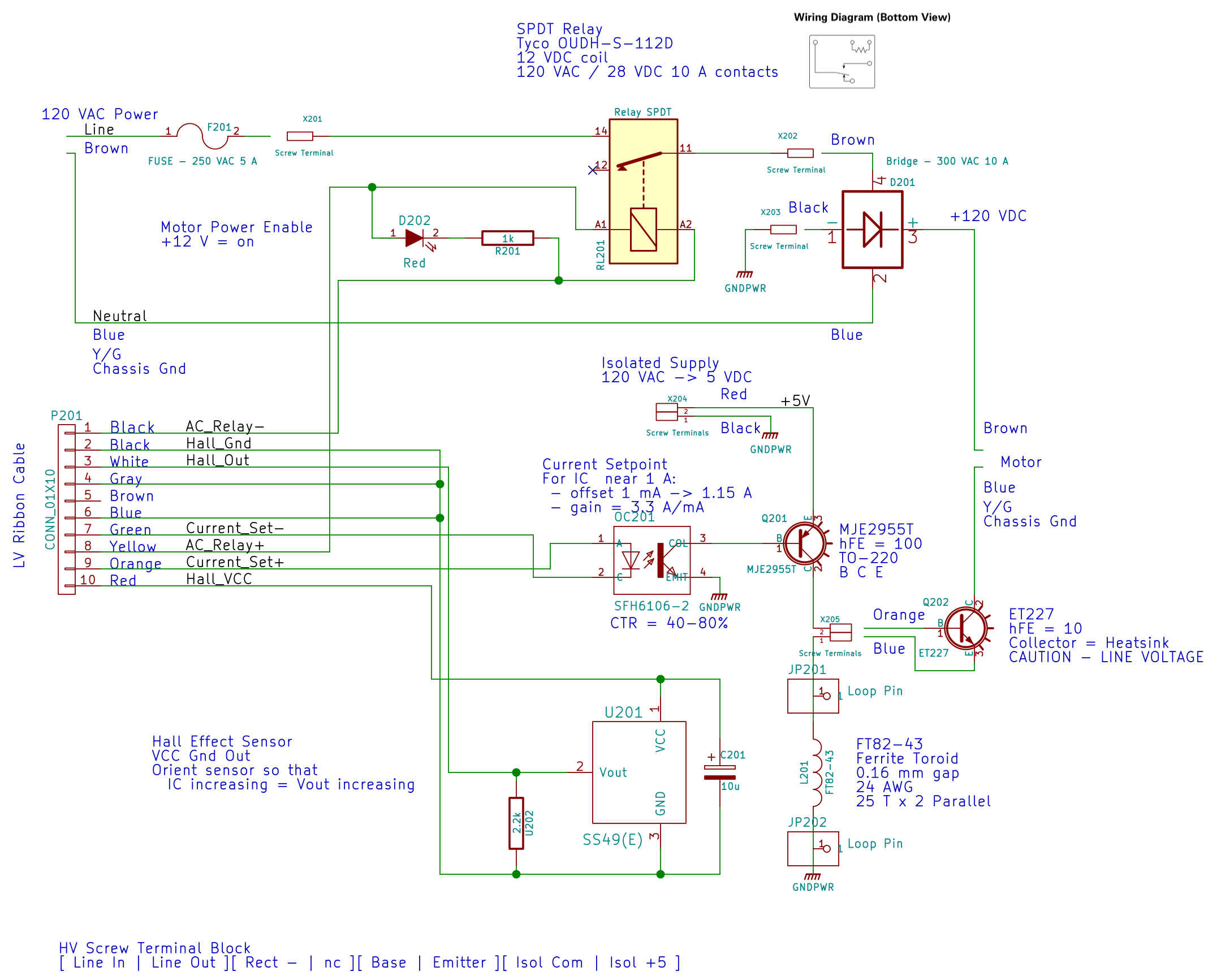
AC Power Interface
The driver lives on the Low Voltage Interface board:
LV Power Interface – AC Relay driver
The GX270’s front-panel hard drive LED now serves to indicate when the AC power goes live.
I’d originally intended to turn the AC on when the Arduino gains control, but after seeing those pictures, I think it’ll remain disabled unless there’s a call for motor motion.
The interlock switch closes when the case opens, grounding the transistor base and disconnecting the AC power.
Of course, you can cheat by simply unplugging the switch, so it’s not failsafe. If you want failsafe, you need a normally closed switch in series with the collector; that’s not what Dell used as a chassis intrusion switch. That’s my story and I’m sticking with it.
Not much rain fell around here during September, lowering the Mighty Wappingers Creek and exposing the rubble of the dam at Red Oaks Mill:
Red Oaks Mill dam – stonework – 2014-09-06
We never noticed the stonework along the far bank; it’s usually underwater.
Some smooth water-worn wood and stone:
Red Oaks Mill dam – 2014-09-06
I’ve always wanted to live in the powerhouse of a small dam. If somebody ever rebuilds this poor thing for low-head hydropower, they’ve got a live-in generator tender…
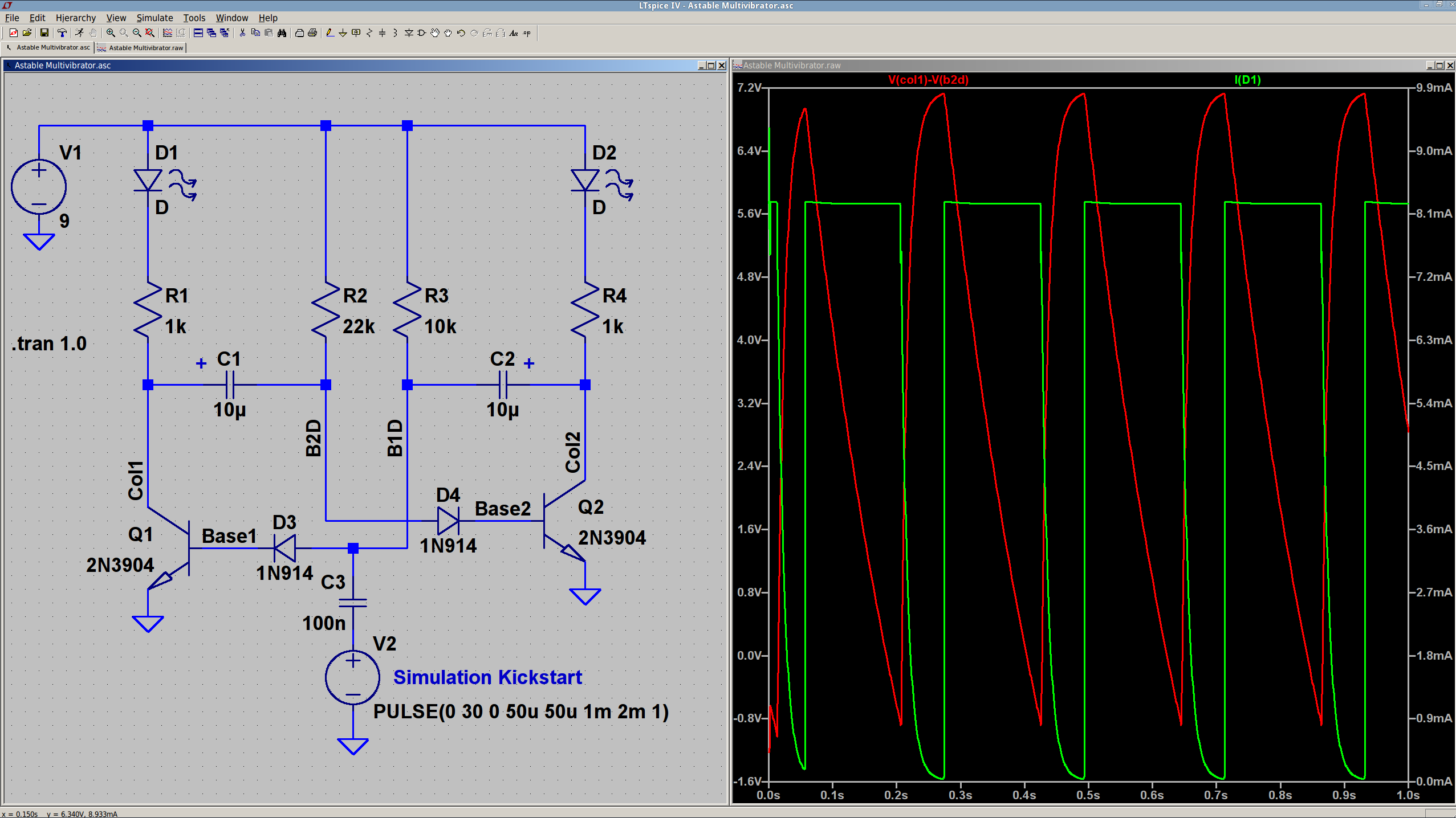
The 10 µF caps scale the output to visible blinkiness. Their polarity may seem backwards, but the red trace in the simulation shows that the net voltage is positive in that direction for nearly the entire cycle. They see only two forward biased junctions in the other direction, so they shouldn’t blow up.
I built it with resistors from the SqWr junk box parts cabinet that were close to the nominal values.
Connecting the transistor base / cap charging resistors to the power supply, rather than the LEDs, gets rid of the tiny current when the LEDs should be off.
The cap-and-pulse-generator dingus on the bottom kickstarts the simulation; it doesn’t have any physical significance.
Memo to Self: Build one with a pair of ET227 transistors and some 100 W tungsten bulbs…
Although I plan to servo the motor speed to the pedal position, a quick open-loop test seems in order. The motor requires nigh onto half an amp before it can spin the sewing machine shaft, so this chunk of Arduino code scales-and-offsets ten bits of pedal position voltage into twelve bits of DAC output that produce a corresponding current limit for the motor winding:
Putting that in the Arduino’s main loop and holding the pedal down produces this pleasant result:
Current Sense Amp vs Tek – 200 mA-div
The current sense amp output in the top trace is scaled at 525 mA/V = 525 mA/div and the bottom trace is from the Tek current probe at 200 mA/div. Fiddling with the scope’s gain & offset exactly overlays the two traces and they remain overlaid through the full pedal travel, so the ferrite toroid isn’t saturating and the output remains nicely linear.
The flat tops in that picture show the ET227 transistor limiting the motor current to 600 mA, exactly the way it should.
Of course, the LM324 has a GBW = 1 MHz and, with a gain of three, a bandwidth of barely 300 kHz, so there’s a distinct lack of fuzz on that trace compared to the Tek probe’s 10 MHz bandwidth.
It’s easy to hold the sewing machine at a constant speed with a constant load, but touching the handwheel stalls the motor at a constant pedal position. Similarly, releasing the handwheel causes a runaway, unless I let up on the pedal fairly quickly.
Setting the Tek probe to 500 mA/div and triggering on a somewhat higher current while stomping on the pedal and grabbing the sewing machine’s handwheel shows the current increasing with the motor under heavier load:
Model 158 – Current sense vs Tek 500 mA-div
The current limit reaches just under 2 A, over on the right side, for both traces.
So the hardware works pretty much the way it should.
After years of neglect, an NYS DOT crew started a really nice repair job on the inside edge of the curve just north of our house. They milled out the deteriorated road surface, cleaned out the debris, and laid in a patch flush with the road surface. That’s quite unlike their usual shovel-some-cold-patch / hand-tamp / drive-over-it process, made familiareverywhere elsearound here.
Unfortunately, for unknown reasons, they didn’t fill in the last two feet of the milled-out trench, leaving a tooth-shattering pair of perpendicular edges exactly where you’d least expect them:
Rt 376 north of Heathbrook – unfinished patch
Ran out of asphalt? Lunch break? Called off to another emergency? We’ll never know.
I sent a note, with that picture, to the NYS DOT Bicycle & Pedestrian Coordinator, asking what happened; perhaps they planned another layer atop the whole curve to seal the rest of the cracked pavement?
The next day a crew filled in the hole, which I find far more than coincidental.
Although it’s better than it was, there’s now a joint that will deteriorate more rapidly than the uniform asphalt layer they should have created.
The season of giantorb-weavingspiders comes again to Poughkeepsie, with this one stretching a web across the decorative grasses bracketing the (unused) front door:
Orb spider – at rest
While I screwed around with the camera, she dashed off to one side and began wrapping a package:
Orb spider – wrapping insect
Her spinnerets release a torrent of silk during that operation!
Dragging it back to the middle of her orb, she settled down for breakfast.
Orb spider – ready for breakfast
So did I…
Hand held with the Sony DSC-H5, facing westward in dawn light, using the flash to bring the image up out of the mud. A touch of unsharp mask and some contrast stretching; nothing too drastic.
Given that the motor current amounts to maybe 3 A, absolute maximum, with a locked rotor, those skinny wires on the slit ferrite toroid won’t pose a problem:
HV Interface board – detail
I really like how that 3D printed armor worked out, even if I still haven’t poured any goop around the windings to lock them down; they’re held in by raw faith and friction.
The current sense circuitry appears along the bottom of the AC Power Interface schematic:
AC Power Interface
The differential amplifier lives on the Low Voltage Interface board, forming the clump of parts just in front of the LM324 op amp on the left:
Low Voltage Interface Board – detail
Which has the usual handful of components required to get anything done in the analog realm:
Current Sense Amp – schematic
The power supplies come directly from the ATX connector. I’m ignoring the whole decoupling issue, because the supplies have essentially no load (and it’s all DC, anyway).
The trim pot sets the offset voltage to bring the Hall effect sensors’s VCC/2 offset down close to zero; the 100 mV figure is nominal, not actual, but should be a bit over 0 V to allow for a wee bit o’ drift. This time around, I’ll measure and subtract the actual offset, rather than (try to) auto-zero it.
The voltage gain runs just under 3, set by 1% resistors from the heap. The overall gain works out to about 1.9 V/A or 525 mA/V, setting the high end at 5 V to a scant 2.6 A. Subject to actual calibration with more attention to detail, that’s close enough; we’re more interested in the around-an-amp range where the motor operates under nominal load.
The nose-to-tail Schottky diodes clamp the op amp output to avoid annoying the Arduino’s ADC input. It has protection circuitry, too, but there’s no point in stressing it.