We’ve been kicking around ideas for introductory soldering / electronics projects at Squidwrench, which prompted me to come up with a classic astable multivibrator circuit:
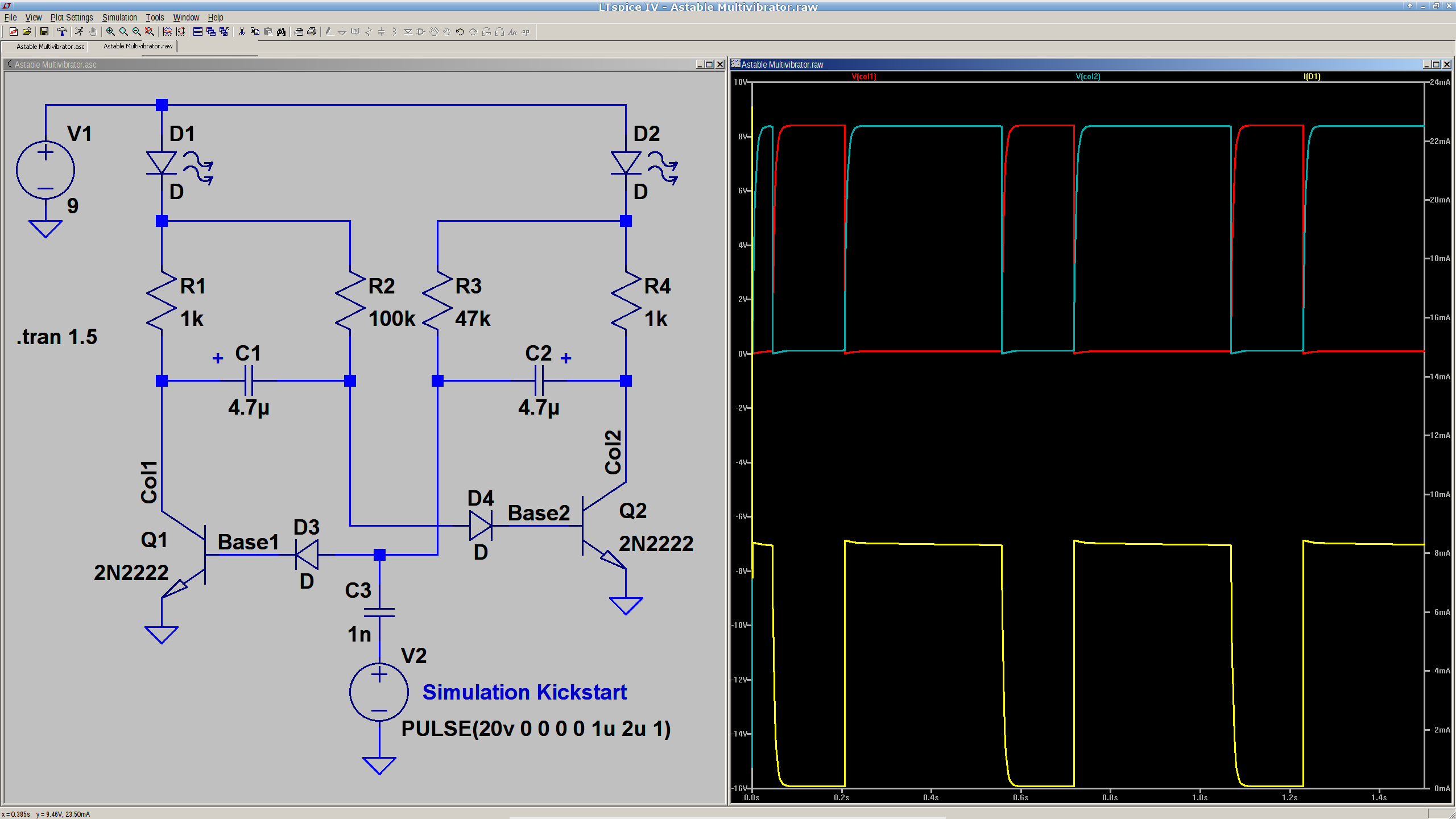
Everything is totally non-critical: it should oscillate as long as the base resistors are small enough to lightly saturate the transistors. The LEDs let you know it’s actually working.
You’d probably want a few decades of caps and a decade’s worth of resistors on pin headers, so as to cover the range from visible blinkiness to nasty audio squeal.
The pulse generator and cap at the bottom apply a jolt at T=0 to knock the circuit off balance. Otherwise, the simulation will just sit there and do nothing; in the real world, of course, nothing stays balanced for very long.

Comments
3 responses to “Soldering Project: Astable Multivibrator”
Are D3 and D4 required? I remember building variations of this when I was a kid, and don’t recall using diodes (the LEDs, on the other hand, are a good idea).
When the circuit switches state the timing caps yank the bases a little less than VCC below ground. That voltage probably exceeds the reverse-bias breakdown for most emitter-base junctions and, there being no current limiting, it may very well scorch the junctions.
So, while the diodes aren’t strictly necessary, it’s much easier to treat them as More Soldering Practice than having a novice troubleshoot a dead transistor…
According to the Phillips datasheet, they guarantee BVebo to be 5V. Methinks the lack of any more significant digits says it’s a Real Good Idea to keep those diodes. The process we used gave us about 7V BVebo (as memory serves), but that’s going to be unique to each process…