Our Larval Engineer practiced fencing for several years, learning the fundamental truth that you should always bring a gun to a knife fight:

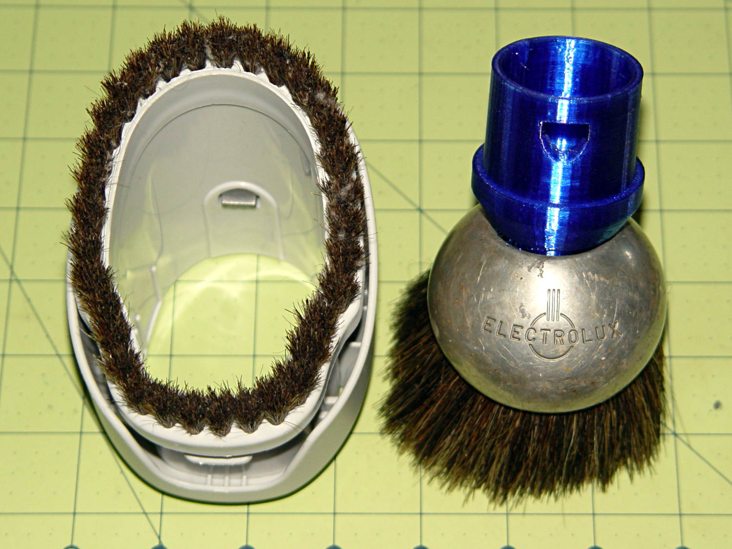
It’s time to pass the gear along to someone who can use it, but we discovered one of the ear grommets inside the helmet had broken:
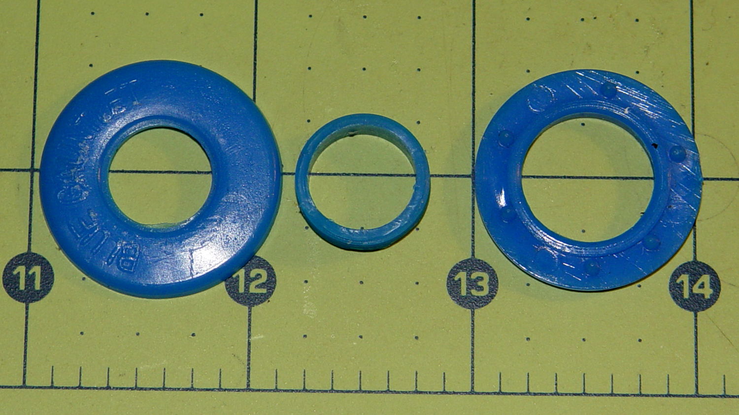
The cylinder in the middle should be attached to the washer on the left, which goes inside the helmet padding. It’s a tight push fit inside the washer on the right, which goes on the outside of the padding. Ridges along the cylinder hold it in place.
Being an injection-molded polyethylene part, no earthly adhesive or solvent will bother it, soooo… the solid model pretty much reproduces the original design:
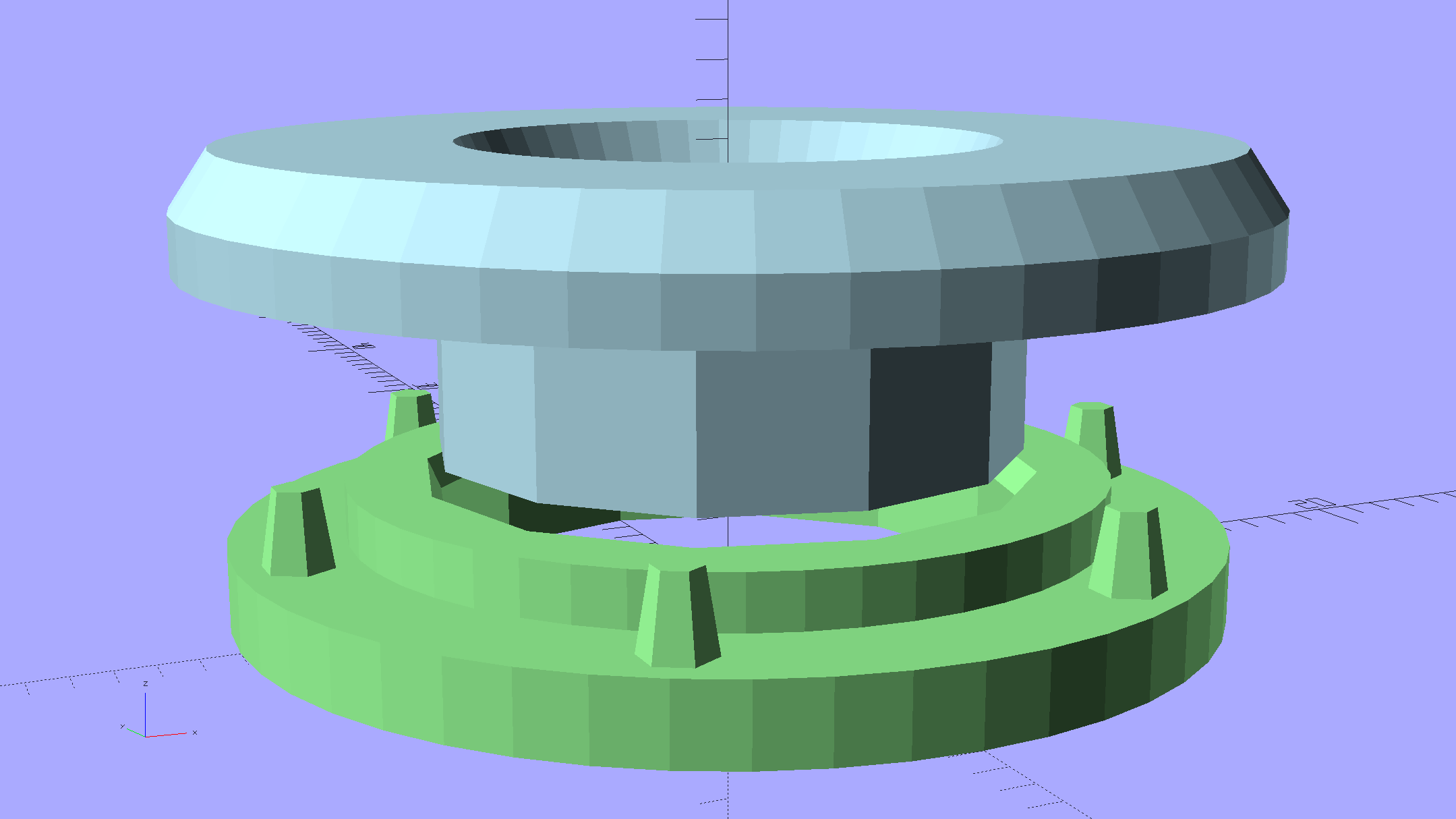
The top washer goes inside the padding against your (well, her) ear, so I chamfered the edges sorta-kinda like the original.
There are no deliberate ridges on the central cylinder, but printing the parts in the obvious orientation with no additional clearance makes them a very snug push fit and the usual 3D printing ridges work perfectly; you could apply adhesive if you like. The outside washer has a slight chamfer to orient the post and get it moving along.
The posts keep the whole affair from rotating, but I’m not sure they’re really necessary.
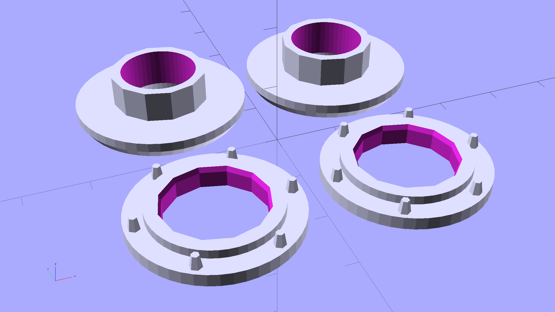
Printing a pair doesn’t take much longer than just one:
It doesn’t look like much inside the helmet:

The OpenSCAD source code as a gist from Github:
| // Fencing Helmet Ear Grommet | |
| // Ed Nisley KE4ZNU December 2015 | |
| // Layout options | |
| Layout = "Show"; // Base Cap Build Show | |
| //- Extrusion parameters must match reality! | |
| // Print with +1 shells and 3 solid layers | |
| ThreadThick = 0.20; | |
| ThreadWidth = 0.40; | |
| HoleWindage = 0.2; | |
| function IntegerMultiple(Size,Unit) = Unit * ceil(Size / Unit); | |
| Protrusion = 0.1; // make holes end cleanly | |
| //———————- | |
| // Dimensions | |
| NumSides = 12*4; | |
| $fn = NumSides; | |
| //———————- | |
| // Useful routines | |
| module PolyCyl(Dia,Height,ForceSides=0) { // based on nophead's polyholes | |
| Sides = (ForceSides != 0) ? ForceSides : (ceil(Dia) + 2); | |
| FixDia = Dia / cos(180/Sides); | |
| cylinder(r=(FixDia + HoleWindage)/2, | |
| h=Height, | |
| $fn=Sides); | |
| } | |
| //——————- | |
| // Parts | |
| // Base on outside of liner | |
| PostOD = 15.5; | |
| PostLength = 8.0; | |
| BaseOD = 26.0; | |
| BaseLength = 3.4; | |
| module Base() { | |
| difference() { | |
| union() { | |
| cylinder(d=BaseOD,h=2.0); | |
| cylinder(d=20.0,h=BaseLength); | |
| for (i=[0:5]) | |
| rotate(i*360/6) | |
| translate([11.5,0,0]) | |
| rotate(180/6) | |
| cylinder(d1=2.5,d2=3*ThreadWidth,h=4.0,$fn=6); | |
| } | |
| translate([0,0,-Protrusion]) | |
| // PolyCyl(PostOD,4.0,NumSides/4); | |
| cylinder(d=PostOD,h=PostLength,$fn=NumSides/4); | |
| translate([0,0,(BaseLength – 4*ThreadThick)]) | |
| cylinder(d1=PostOD,d2=(PostOD + 2*ThreadWidth),h=(4*ThreadThick + Protrusion),$fn=NumSides/4); | |
| } | |
| } | |
| // Cap inside liner | |
| CapID = 12.0; | |
| CapOD = 28.0; | |
| CapThick = 3.0; | |
| module Cap() { | |
| difference() { | |
| union() { | |
| rotate_extrude(convexity=2) | |
| polygon(points=[ | |
| [CapID/2 + CapThick/3,0.0], | |
| [CapOD/2 – CapThick/3,0.0], | |
| [CapOD/2,CapThick/2], | |
| [CapOD/2,CapThick], | |
| [CapID/2,CapThick], | |
| [CapID/2,CapThick – CapThick/3] | |
| ]); | |
| translate([0,0,CapThick – Protrusion]) | |
| cylinder(d=PostOD,h=(PostLength – (CapThick – Protrusion)),$fn=NumSides/4); | |
| } | |
| translate([0,0,-Protrusion]) | |
| PolyCyl(CapID,10.0,$fn); | |
| } | |
| } | |
| //———————- | |
| // Build it! | |
| if (Layout == "Base") | |
| Base(); | |
| if (Layout == "Cap") | |
| Cap(); | |
| BuildSpace = 30/2; | |
| if (Layout == "Build") { | |
| for (j=[-1,1]) | |
| translate([j*BuildSpace,0,0]) { | |
| translate([0,-BuildSpace,0]) | |
| Base(); | |
| translate([0,BuildSpace,0]) | |
| Cap(); | |
| } | |
| } | |
| if (Layout == "Show") { | |
| color("LightGreen") Base(); | |
| translate([0,0,12]) | |
| rotate([180,0,0]) | |
| color("LightBlue") Cap(); | |
| } |