Ed Nisley's Blog: Shop notes, electronics, firmware, machinery, 3D printing, laser cuttery, and curiosities. Contents: 100% human thinking, 0% AI slop.
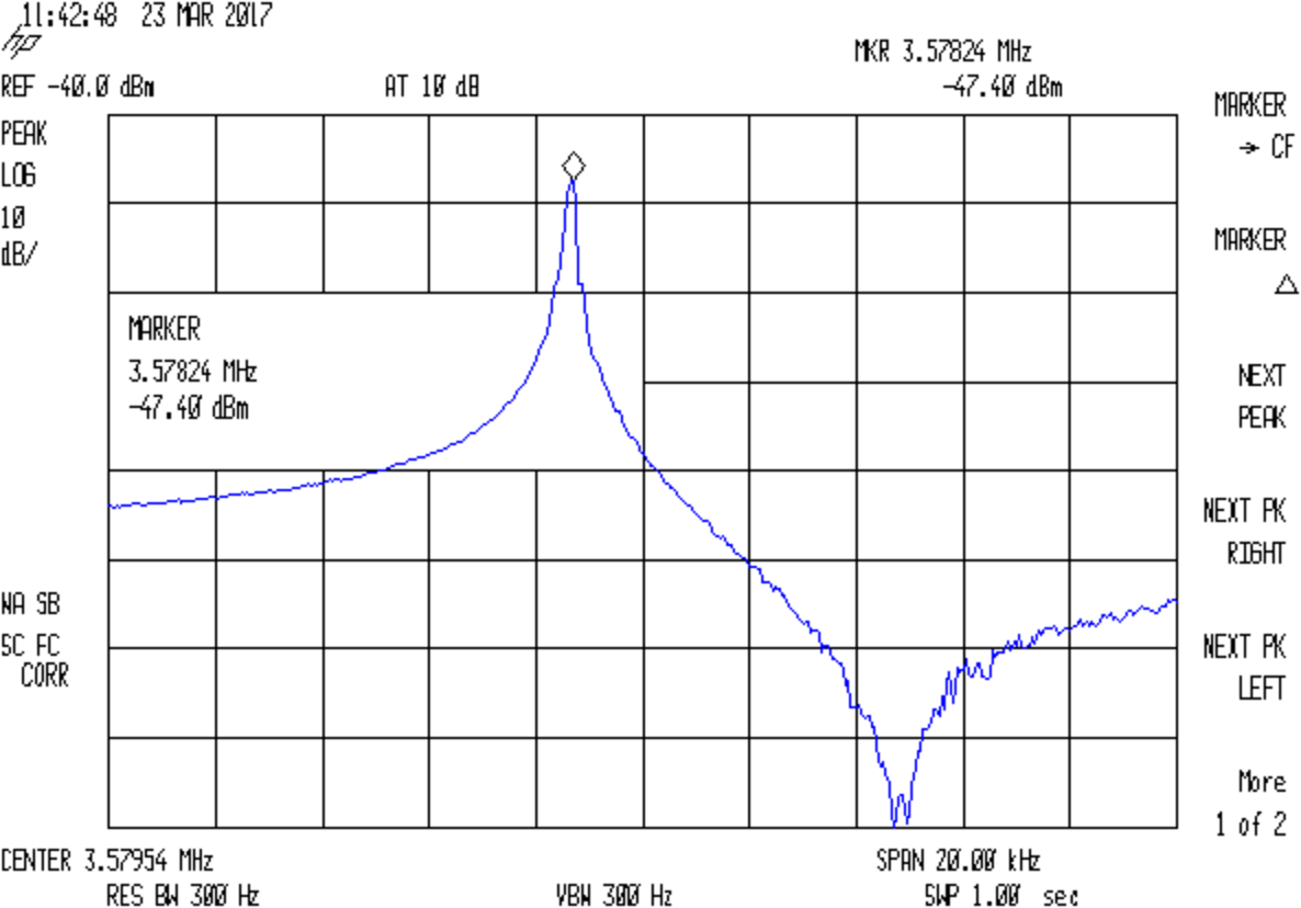
The reference level is -40 dBm, not the usual 0 dBm, due to the loss in those resistive pads. Unsurprisingly, the parallel resonance valley looks pretty ragged at -120 dBm = 1 nW = 7 µV.
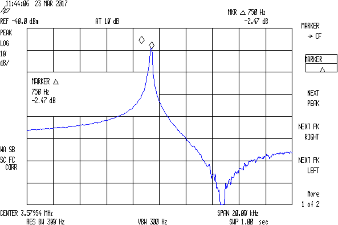
Remove the jumper to put the capacitor in series:
Quartz 3.57954 MHz – 36.4pF
The marker delta resolution surely isn’t 1 Hz, but 750 Hz should get us in the right ballpark.
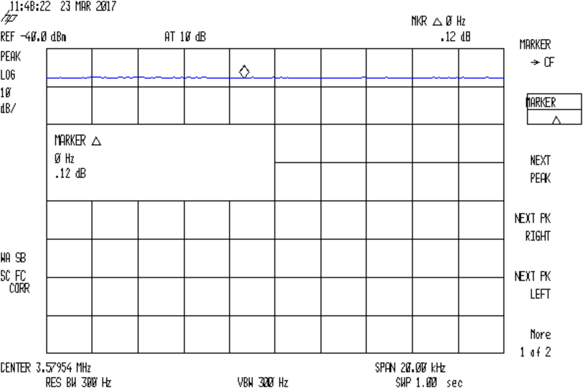
Substituting a 72 Ω resistor, found by binary search rather than twiddling a pot:
Quartz 3.57954 MHz – 72ohm
Which gives us all the measurements:
Fs = 3.57824 MHz
Fc = Fs + 750 Hz = 3.57899 MHz
Rm = 72 Ω
C0 = 3.83 pF
Cpar = 3.70 pF
Turn the crank and the crystal motional parameters pop out:
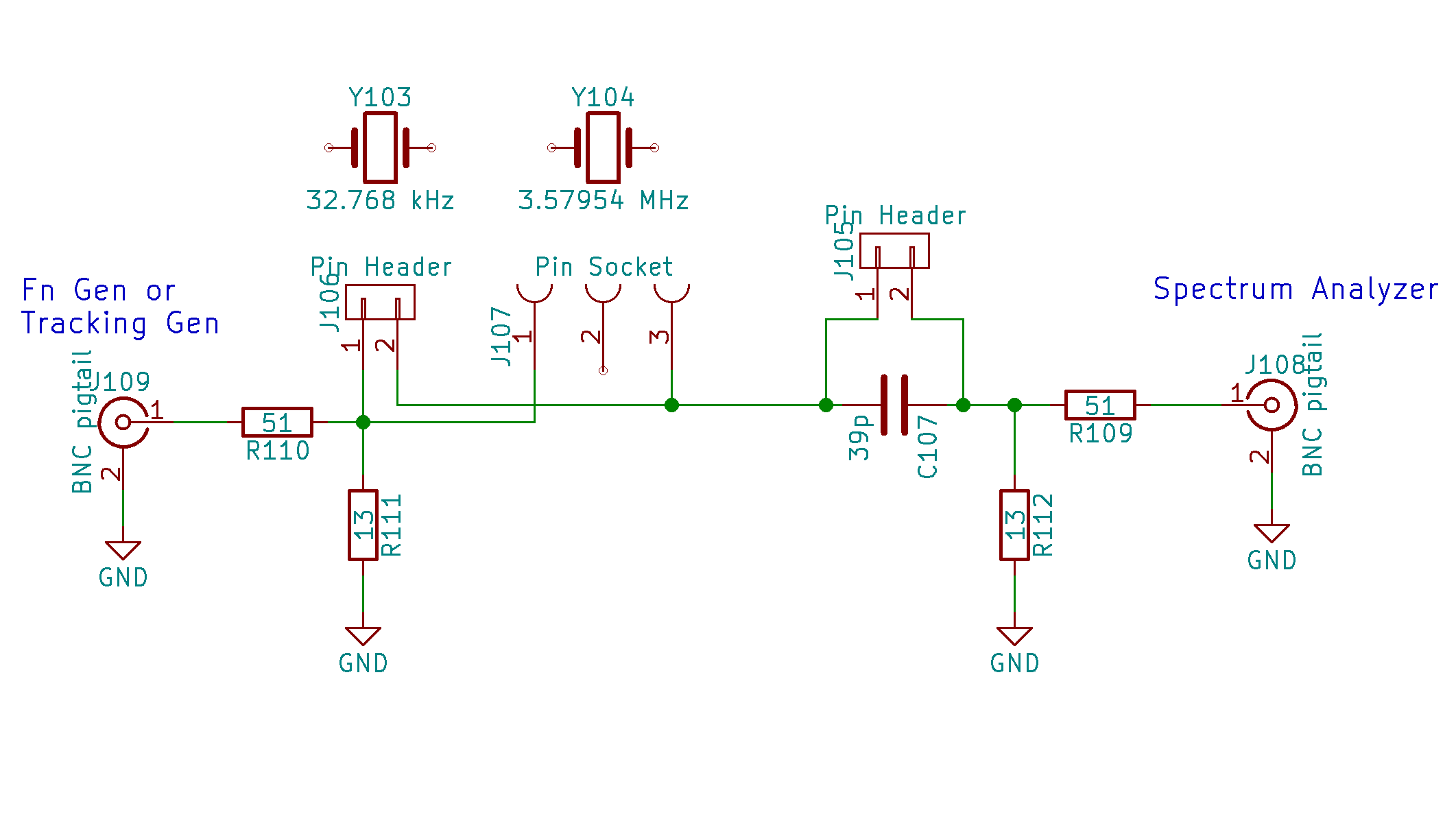
A recent QEX article (Jan/Feb 2017 2016; sorry ’bout that), Crystal Measurement Parameters Simplified, Chuck Adams K7QO) suggested a simplified version of the K8IQYcrystal parameter test fixture would work just as well for low-frequency quartz resonators:
Quartz crystal resonance test fixture – schematic
The resistive pads eliminate the fussy toroids and their frequency dependence.
I found two absurdly long hunks of RG-174 coax with BNC connectors, so that’s how it connects to the outside world; sacrificing a short SMA jumper would reduce the clutter, but that’s in the nature of fine tuning. At the frequencies this fixture will see, coax properties don’t matter.
I can’t think of a better way to mount those AT26 cans than by soldering the wire leads directly to a pin header; pushing them under spring clips seems fraught with peril, not to mention excessive stray capacitance.
Measure the actual in-circuit capacitance for the 33 pF cap (shown as 39 pF in the schematic, it’s not critical), which worked out to 34.6 pF. That’s the external series capacitance Cx.
The overall procedure, slightly modified from the original:
Crystals (or resonators) in AT26 packages have vanishingly small capacitances, so I conjured a little fixture for my AADE L/C Meter IIB (*) that holds them securely under little fingers snipped from an EMI shield:
AT26 crystal capacitance fixture – Cpar detail
The finger on the right sits atop a snippet of rectangular brass tube so it need not bend so far.
The base is a snippet of double-sided PCB with copper tape soldered around the edges. I drilled the holes slightly oversize and soldered copper tape there, giving the top foil a direct connection to the terminals. The raggedy slot looks like it came from a hacksaw; no false advertising there.
The meter reports 6.5 pF of stray capacitance and nulls it to zero as usual. Without the fixture, it shows 2.5 pF.
With the crystal in that position, the meter measures Cpar, the parasitic capacitance from both terminals to the can, which should be (roughly) twice the capacitance from either terminal to the can.
Two more clips measure C0, the plate-to-plate capacitance:
AT26 crystal capacitance fixture – C0 detail
The meter drive is about 200 mV at 700 kHz, far away from resonance. Assuming the resonator’s effective series resistance is 25 kΩ (tuning forks aren’t crystals!), it’s dissipating 1.5 µW (and less as the ESR goes up). That may be slightly hot for some resonators, but it’s surely survivable.
Some preliminary data on five 32.768 kHz crystals shows Cpar = 0.4 pF and C0 = 0.9 pF. I don’t trust those numbers very much, but they’re reproducible within 0.1-ish pF.
(*) Almost All Digital Electronics and its website vanished after the owner died; the meter continues to work fine. The cheap knockoffs flooding eBay and Amazon may get you close to the goal.
Apparently she wanted to use the bird feeder atop the post festooned with plastic squirrel deterrence. Not being Elastigirl, she couldn’t quite stretch from rail to feeder, eventually gave up trying, and flapped to the driveway.
We’ve been turkey-watching for nearly two decades, it’s been eight years since we saw a turkey on the patio, and a few days after I set up the yard camera, shazam, this bird shows off for my friend in Raleigh while I’m in the Basement Laboratory. I’m insane with jealousy.
In point of fact, turkeys seem perfectly aware of people inside the house, so it’s not surprising they avoid the patio. When we move close to a window, the flock decides it has business elsewhere and, generally without haste or confusion, flows over the hill and away.
Obviously, I must set up motion detection and capture some images …
We spotted this on our regular walk around the block:
Plastic fence vs snow
The horizontal rails have a latching ramp that’s good enough in most circumstances:
Plastic fence – rail latch detail
Perhaps those latches released as designed under an overload. The snowplow would have been traveling toward us on that side of the road and pushed the snow against the fence panels hard enough to dislodge the rail latches from their sockets.
I suppose they can zip the fence panels back in place, one by one, without rebuilding the whole affair.
Thinking of a 60 kHz crystal filter front end for the WWVB receiver brought a little bag of 32.768 kHz crystals to the surface; I figured I could use them as crash test dummies while a bag of 60 kHz crystals travels around the planet. Come to find out they don’t behave quite like crystals and a bit of investigation shows the little cans contain tuning fork resonators, not crystal slabs.
I had to see that, so I grabbed the base of one in a pin vise:
Quartz resonator – pin vise
I don’t know the part number for those resonators, but it’s something like AT26, where the “26” means a cylindrical can 2 mm OD and 6 mm long, more or less.
Notching the can at the chuck with a triangular file, then wiggling the can with needle-nose pliers, eventually broke it off:
Quartz resonator – A side
The other side:
Quartz resonator – B side
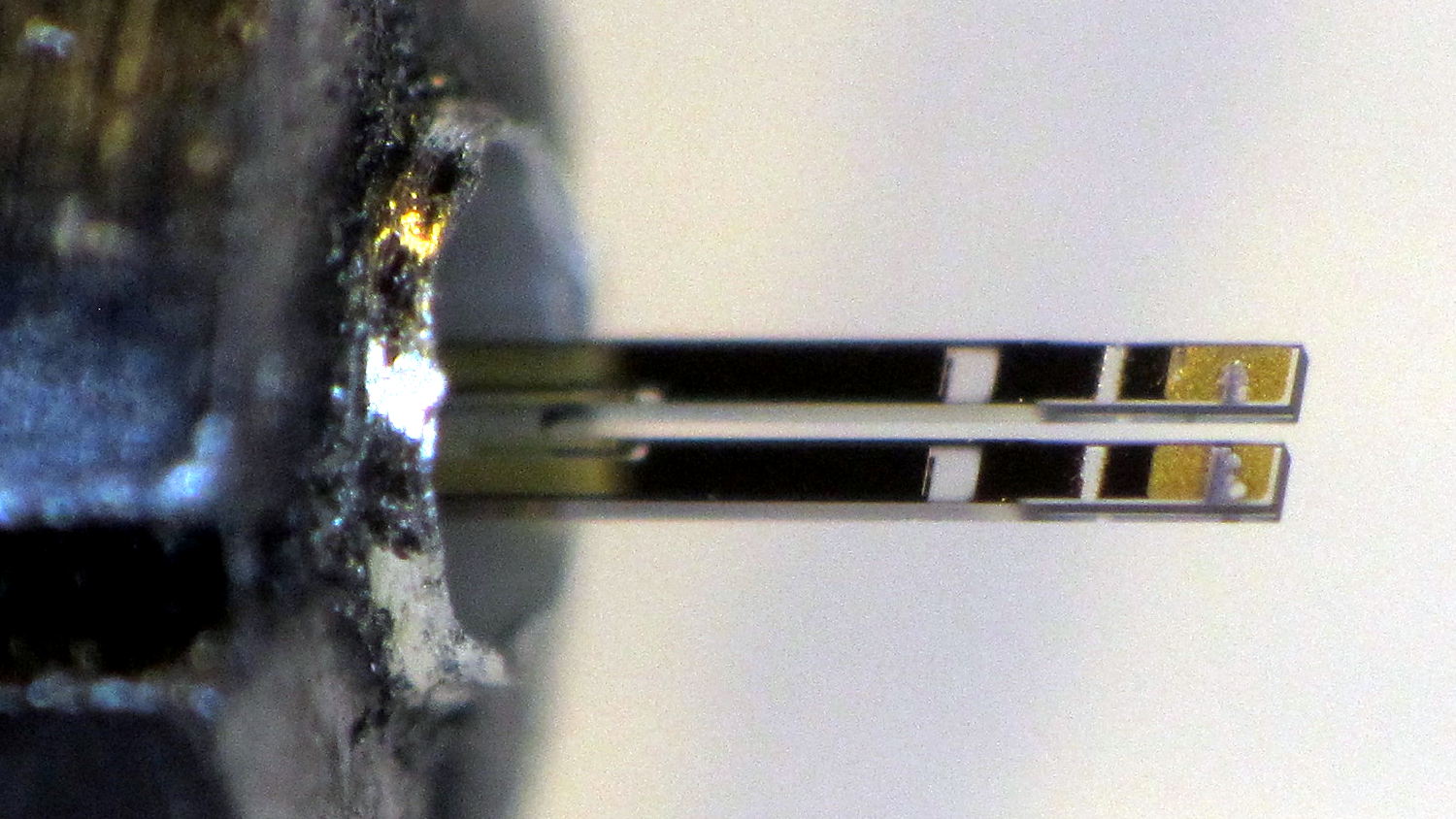
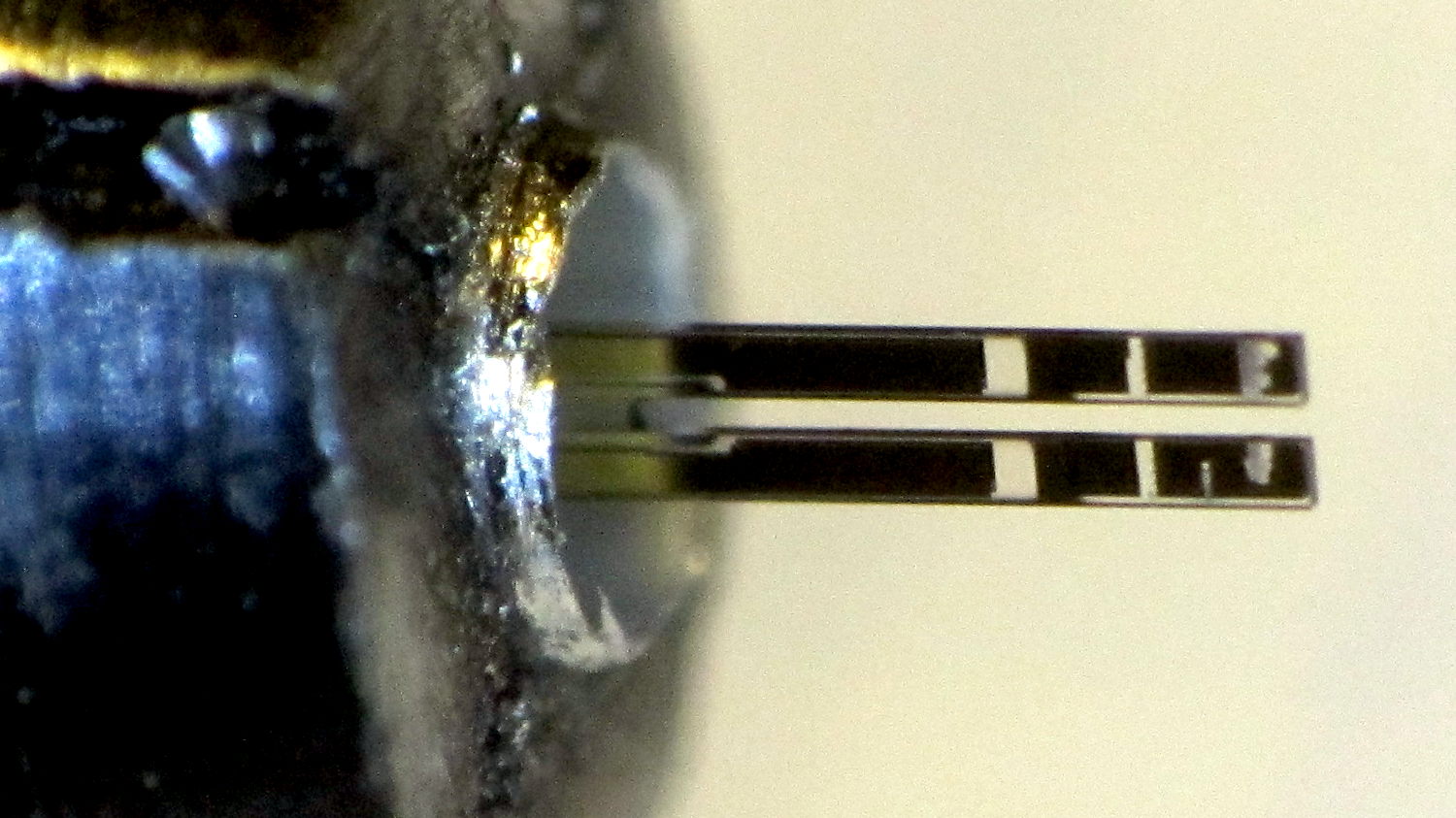
A look through the microscope show they’re transparent, with laser trim scars on the ends:
Quartz resonator – detail
The “holes” are unplated quartz areas, clear as the finest glass.
At first, the yard camera worked fine, but a few days later the stream of JPEG images would unpredictably stall. I connect to it through a public-key SSH session and, sometimes, the login would stall for tens of seconds and, with a session set up, various exciting operation like, say, htop would unpredictably stall; if I waited long enough, they’d complete normally.
It’s a known-good card from a reputable supplier, not that that means much these days. The camera flash highlights the gritty silkscreen (?) texture of the orange overlay, but the production value seems high enough to pass muster.
Popping the card in my desktop PC showed:
It remains functional, at least to the extent of being mount-able and write-able
3probe --time-ops /dev/sdb showed it still held 16 GB
fsck -fv /dev/sdb[12] shows no problems
Both partitions looked good
So I shrank the main partition to 7.5 GB, copied the image to the desktop PC’s SSD, fired up the Token Windows Laptop, ran the Official SD Card Formatter, and discovered that it thought the card had only 63 MB (yes, MB) available. That’s the size of the FAT boot partition, so I returned the card to the desktop PC, unleashed gparted on it, blew away the partitions, reformatted the whole thing to one 16 GB FAT32 partition, and stuck it back in the laptop, whereupon the Official Formatter agreed it had every byte it should.
A format-with-overwrite then proceeded apace; the card doesn’t support format-with-erase.
Back in the desktop, I copied the saved image back onto the card which, en passant, blew away the just-created FAT format and restored the Raspbian partition structure. The 8 GB of that copy proceeded at an average 12.1 MB/s. I did not watch the transfer closely enough to notice any protracted delays.
Back in the Pi, the card booted and ran perfectly, sending an image every second to the laptop (now running its usual Mint Linux) on the guest network:
Turkey flock in driveway – 2017-03-21
SSH sessions now work perfectly, too, and commands no longer jam.
So it seems a good-quality MicroSD card can experience protracted delays while writing data, to the extent of tens of seconds, stalling the Pi in mid-operation without producing data errors or any other symptoms.
It’s not clear the Official Formatter does anything that simply copying the image back to the card wouldn’t also accomplish, although overwriting the entire 16 GB extent of the card exercises all the cells and forces the card controller to re/de/un/allocate bad blocks. If, indeed, the blocks are bad, rather than just achingly slow.
Moral of the story: Don’t use MicroSD cards as mass storage devices, at least not for industrial applications that require consistent performance.