Ed Nisley's Blog: Shop notes, electronics, firmware, machinery, 3D printing, laser cuttery, and curiosities. Contents: 100% human thinking, 0% AI slop.
My posts about troubles with the KensingtonExpertMouse scroll ring remain disturbingly popular. My most recent warranty replacement has been running fine for several years, so I suspect they had a bad lot of IR detectors go their production line and into the field.
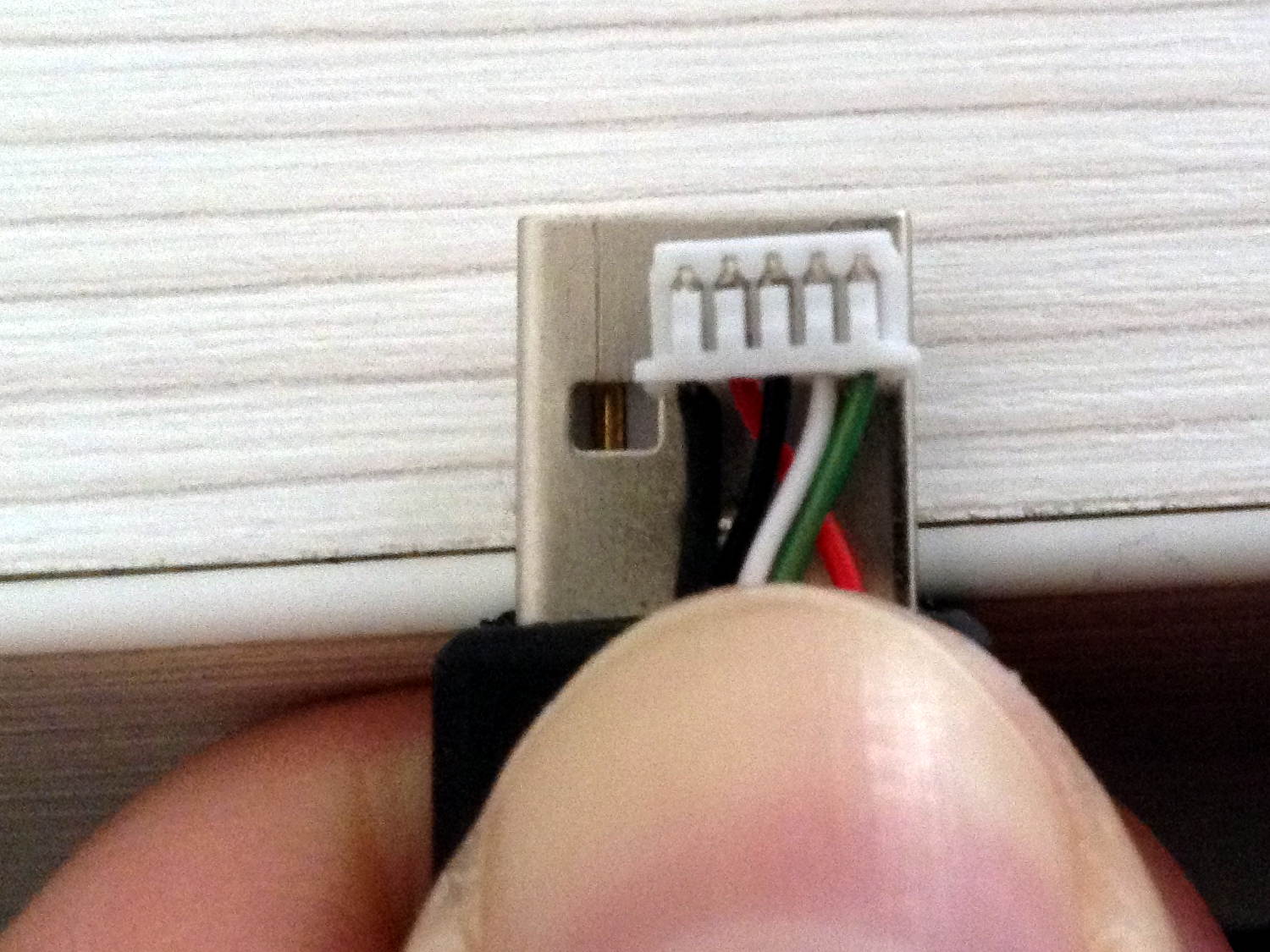
In any event, a recent email asked about where to get the little connector inside the mouse to replace a worn-out USB cable:
Kensington Expert Mouse – internal USB connector
Maybe you’d be lucky enough to find an identical connector inside an old mouse in a junk box, but that’s not the way to bet.
Given that you need not only the proper plastic shell, but also the pins and the crimper for a proper repair, I suggested just chopping the wires an inch from the connector and splicing the new cable onto the wires.
Anyhow, the original cells crapped out after 2-½ years, when these still delivered 13 days. After 4-½ years, they’re lasting 12 days between charges.
Color me surprised, because they’re 600 mA·h NiMH cells. The originals were 2000 mA·h cells, which you’d expect would last longer, but noooo.
No reason to change them yet, which is good news.
FWIW, I recently bought some cheap brush heads from the usual low-end eBay seller. The OEM brushes have colored bristles which fade to tell you when to change brushes, although I run ’em quite a bit longer than that. The cheap replacements have never-fading colored bristles and, I suspect, all the bristles are much too stiff. The dental hygienist says I’m doing great, so it’s all good.
Sonicare brush heads – cheap vs OEM
High truth: at best, you get what you pay for.
(*) Being that type of guy has some advantages, if you’re that guy. Otherwise, it’s a nasty character flaw.
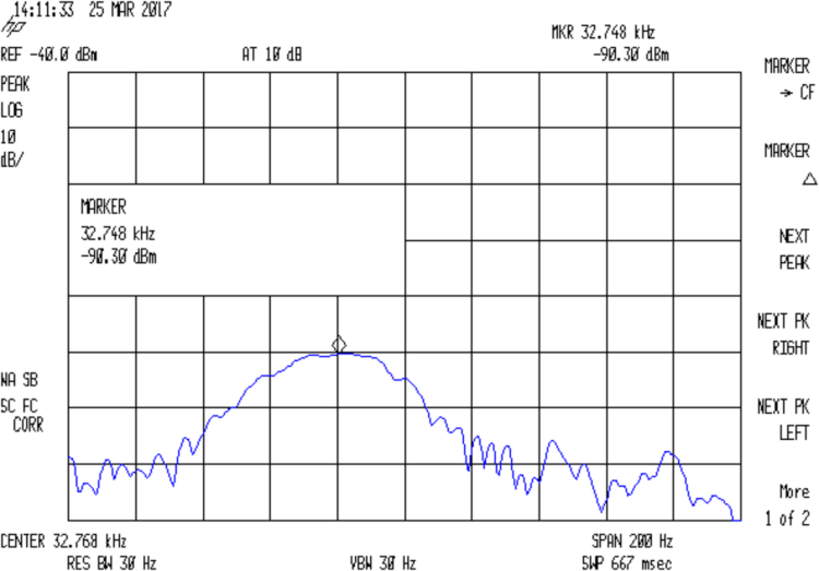
In order to probe a crystal’s response with decent resolution, I need a gadget to step a decent-quality sine wave by 0.01 Hz across the 10-to-100 kHz range and a logarithmic front end with a decent dynamic range. That’s prompted by looking at crystal responses through the SA’s 30 Hz resolution bandwidth:
Quartz Resonator 32.765 kHz – 34.6 pF
Mashing a cheap AD9850/AD9851 DDS board against an Arduino Pro Mini, adding a knob, and topping with a small display might be useful. A Raspberry Pi could dump the response data directly into a file via WiFi, which may be more complication that seems warranted.
The DDS boards come with absurdly high-speed clock generators of dubious stability; a slower clock might be better. A local 10 MHz oscillator, calibrated against the 10 MHz output of the HP 3801 GPS stabilized receiver would be useful. If the local oscillator is stable enough, a calibration adjustment might suffice: dial for 10 MHz out, then zero-beat with the GPS reference, so that the indicated frequency would be dead on to a fraction of 1 Hz.
The HP 8591 spectrum analyzer has a better-quality RF front end than I can possibly build (or imagine!), but, at these low frequencies, a simple RF peak detector and log amp based on the ADL5303 or ADL5306 should get close enough. One can get AD8302 / AD8310chips on boards from the usual low-budget suppliers; a fully connectorized AD8310 board may be a good starting point, as it’s not much more than the single-connector version.
With frequencies from 10 kHz to 100 kHz coming from a local oscillator, one might argue for a synchronous detector, formerly known as a lock-in amplifier. A Tayloe Detector might be a quick-and-dirty way to sweep a tracking-filter-and-detector over the frequency range. Because it’s a tracking generator, the filter bandwidth need not be very tight.
At some point, of course, you just digitize the incoming signal and apply DSP, but the whole point of this is to poke around in the analog domain. This must not turn into an elaborate software project, too.
The HP 8591 tracking generator doesn’t go below 100 kHz, so I used the FG085 DDS function generator as a source. I trust the 8591’s calibration more than the FG805’s, but right now I’m more interested in the differences between successive frequencies and the DDS can step in 1 Hz increments.
The output appears on the 8591, with a big hump comes from the analyzer’s 30 Hz IF filter response sweeping across what’s essentially a single-frequency input. The hump is not the crystal’s response spectrum!
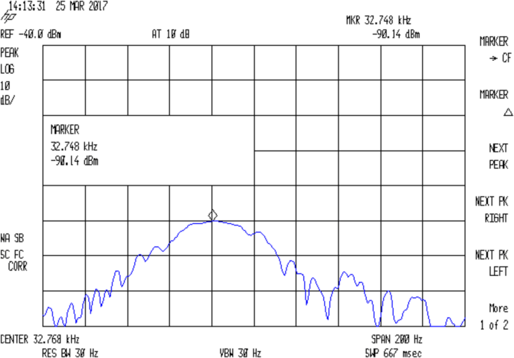
With the jumper installed to short the 33 pF cap, the output peaks at 32.764:
Quartz Resonator 32.763 kHz – no cap
Quartz Resonator 32.764 kHz – no cap
Quartz Resonator 32.765 kHz – no cap
Quartz Resonator 32.766 kHz – no cap
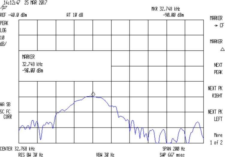
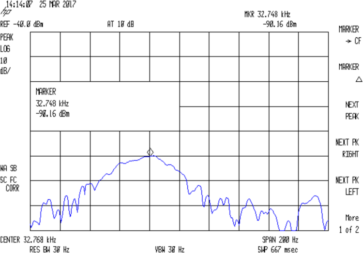
Removing the jumper to put the cap in the circuit, the response peaks at 32.765 kHz:
Quartz Resonator 32.763 kHz – 34.6 pF
Quartz Resonator 32.764 kHz – 34.6 pF
Quartz Resonator 32.765 kHz – 34.6 pF
Quartz Resonator 32.766 kHz – 34.6 pF
The marker delta shows the difference between the two peaks, ignoring their 1 Hz difference:
Quartz Resonator 32.764-5 no-34.6 pF delta
So I’d say the cap really does change the resonator series resonance by just about exactly 1 Hz.
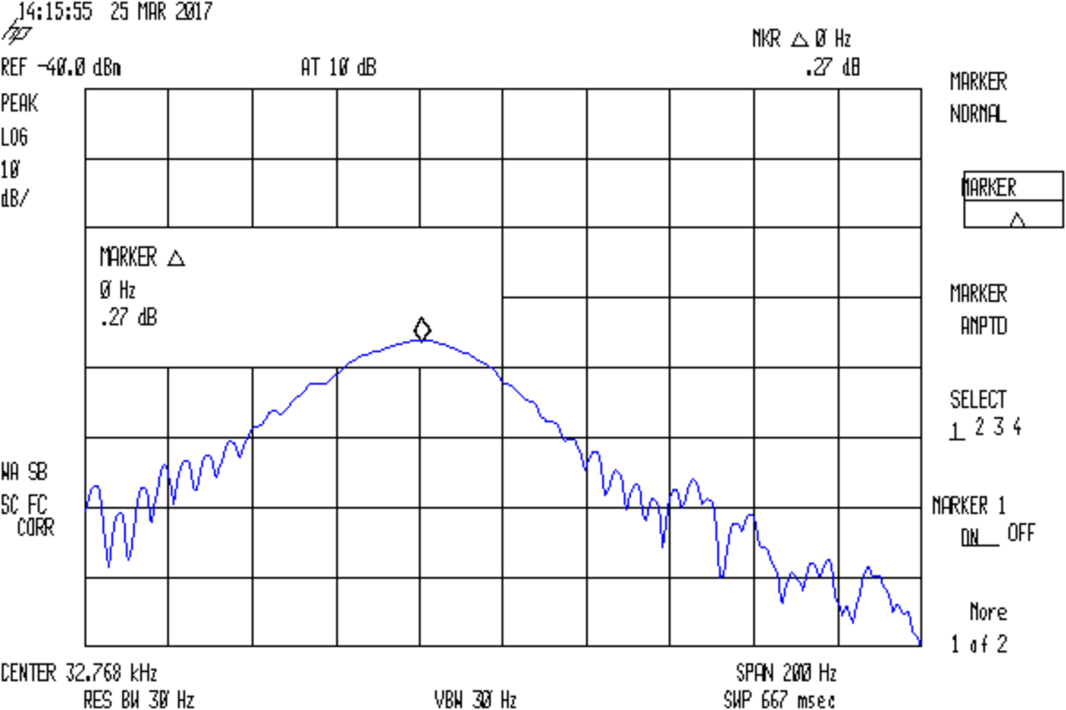
With the jumper installed to remove the cap from the circuit, setting the reference marker at the 32.764 kHz peak, and measuring the relative response at 32.765 kHz :
Quartz Resonator 32.764-5 no cap delta
So the response peak is much much narrower than 1 Hz: being off-peak by 1 Hz knocks 13-ish dB from the response.
What’s painfully obvious: my instrumentation is totally inadequate for crystal measurements at these frequencies!
The reference level is -40 dBm, not the usual 0 dBm, due to the loss in those resistive pads. Unsurprisingly, the parallel resonance valley looks pretty ragged at -120 dBm = 1 nW = 7 µV.
Remove the jumper to put the capacitor in series:
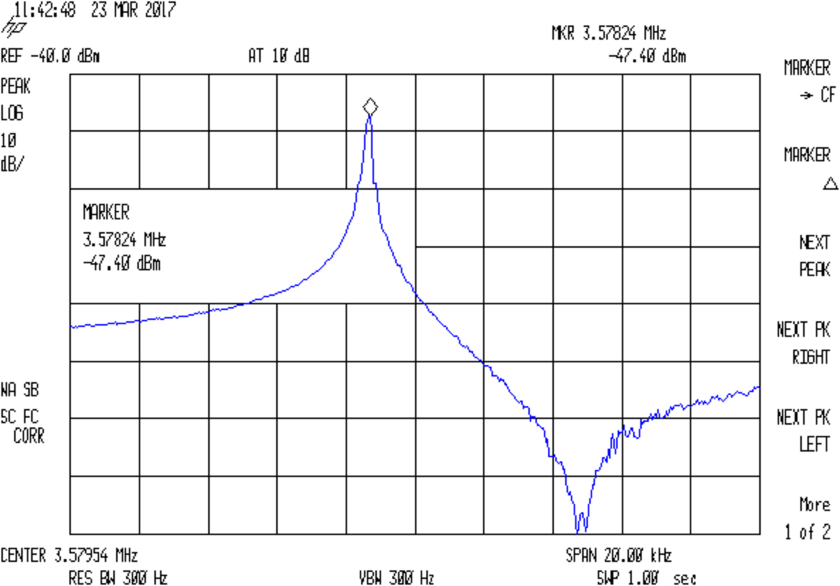
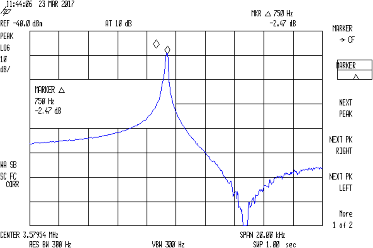
Quartz 3.57954 MHz – 36.4pF
The marker delta resolution surely isn’t 1 Hz, but 750 Hz should get us in the right ballpark.
Substituting a 72 Ω resistor, found by binary search rather than twiddling a pot:
Quartz 3.57954 MHz – 72ohm
Which gives us all the measurements:
Fs = 3.57824 MHz
Fc = Fs + 750 Hz = 3.57899 MHz
Rm = 72 Ω
C0 = 3.83 pF
Cpar = 3.70 pF
Turn the crank and the crystal motional parameters pop out:
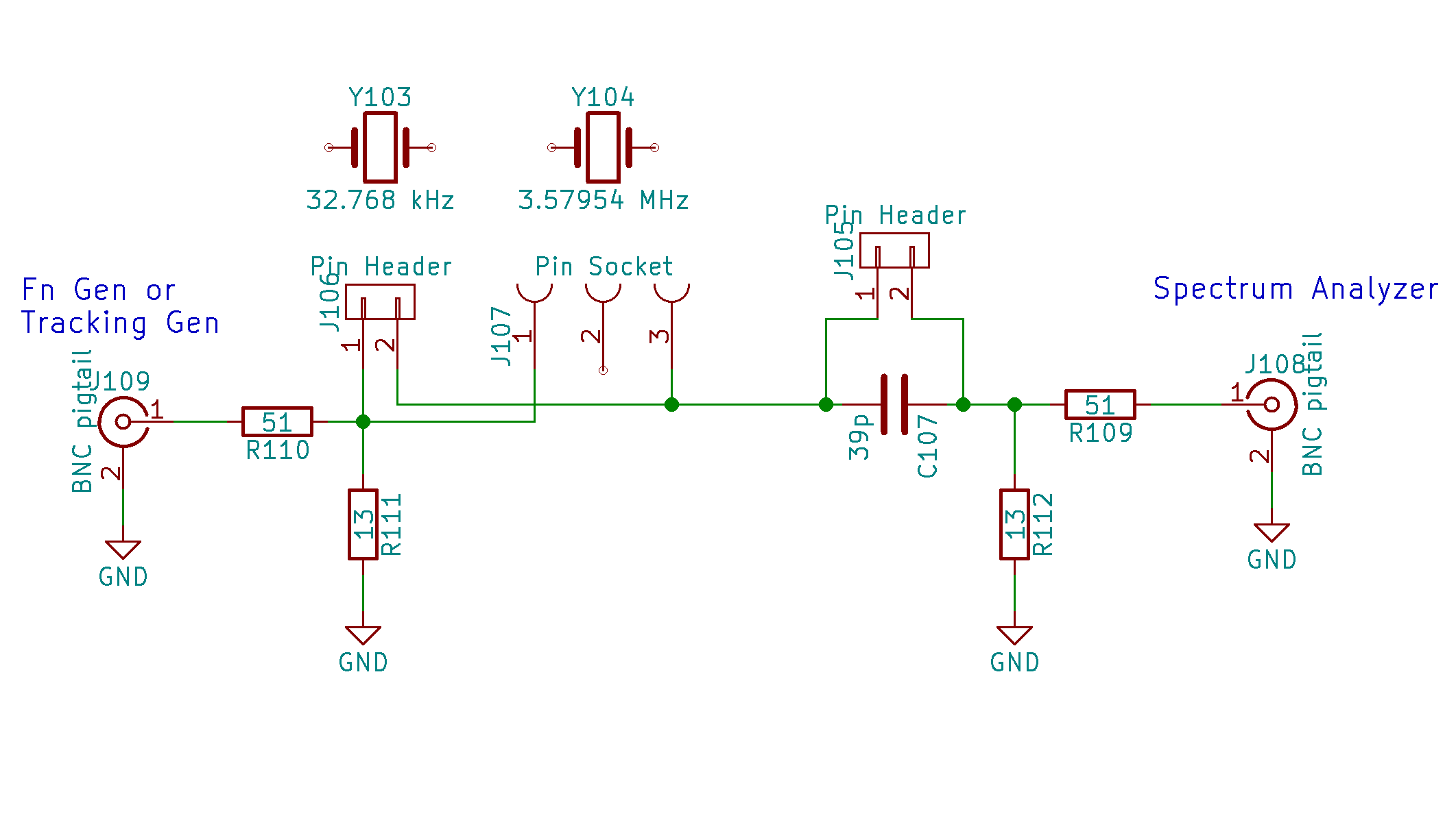
A recent QEX article (Jan/Feb 2017 2016; sorry ’bout that), Crystal Measurement Parameters Simplified, Chuck Adams K7QO) suggested a simplified version of the K8IQYcrystal parameter test fixture would work just as well for low-frequency quartz resonators:
Quartz crystal resonance test fixture – schematic
The resistive pads eliminate the fussy toroids and their frequency dependence.
I found two absurdly long hunks of RG-174 coax with BNC connectors, so that’s how it connects to the outside world; sacrificing a short SMA jumper would reduce the clutter, but that’s in the nature of fine tuning. At the frequencies this fixture will see, coax properties don’t matter.
I can’t think of a better way to mount those AT26 cans than by soldering the wire leads directly to a pin header; pushing them under spring clips seems fraught with peril, not to mention excessive stray capacitance.
Measure the actual in-circuit capacitance for the 33 pF cap (shown as 39 pF in the schematic, it’s not critical), which worked out to 34.6 pF. That’s the external series capacitance Cx.
The overall procedure, slightly modified from the original: