Ed Nisley's Blog: Shop notes, electronics, firmware, machinery, 3D printing, laser cuttery, and curiosities. Contents: 100% human thinking, 0% AI slop.
With the information you shared, we were able to successfully model and reconstruct the drive wheel in only a couple of days.
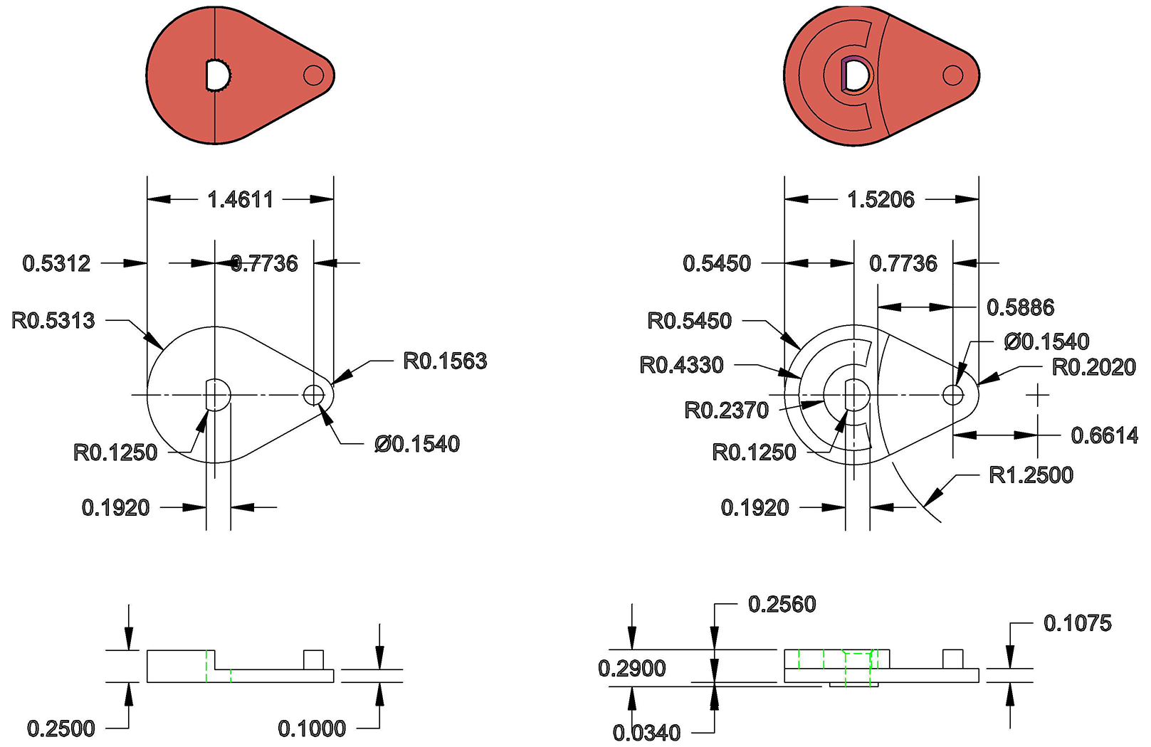
One useful thing we discovered is there’s a lot of room for error – so long as the pin catches and the wheel isn’t slipping on the motor shaft, the mechanism will work. The grooves and the interior radius of the original part aren’t critical.
Because of your heads up about Geneva wheels, I found this excellent website – https://newgottland.com/2012/01/08/make-geneva-wheels-of-any-size/ – which includes a link to a Geneva wheel calculator. With the measurements you sent and a measurement off of the pen carousel, the calculator generated near perfect dimensions for a replacement. There was a little sanding and rounding to fit but it was certainly within tolerance.
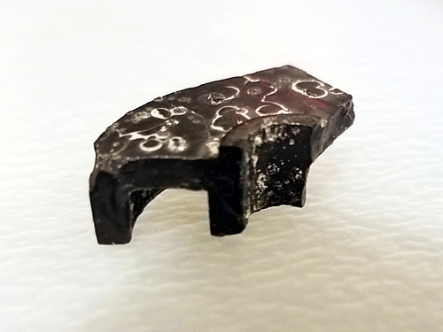
Interestingly, the pieces of the drive wheel that I pulled out of the case revealed a small hidden detail. On the underside, there’s a collar around the motor shaft that gives the cam an extra ~.03″ thickness. Presumably this is to help reduce friction during travel. Our prototype doesn’t take this detail into consideration – we’ve had no issues with friction, and we compensated for the thickness by making the pin a little longer – but it’s meaningful to note.
HP7475A Carousel Drive – cam1
The broken pieces also confirmed the thicknesses and radii of the original part, and so my partner was able to build an accurate technical drawing of the drive wheel for future fabrication.
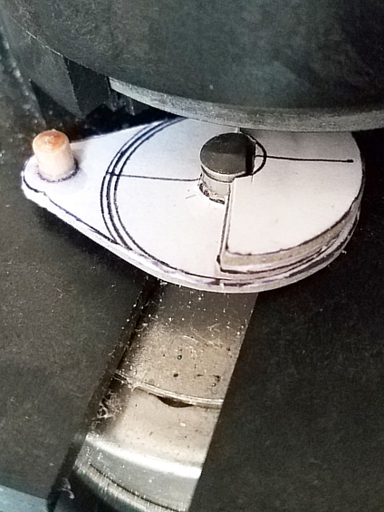
While we intend to make a better replacement, our prototype was built with dense 1/8″ mat board, PVA glue, binder clips, and a short piece of wooden dowel from our bits box. Basically just stuff we had kicking around the studio. It’s held up shockingly well. A little dented around the edges from hitting the carousel, but there’s no slippage. I’m thinking I’ll use it until it falls apart, just to see how long it takes.
HP7475A Carousel Drive – repaired – cam2
Attached, find a technical drawing comparing the original drawing to our prototype (measured in good old fashioned 1980s inches); a photo of the retrieved piece, showing the collar on the reverse side; and a photo of the prototype in place. Feel free to share these – everyone deserves a working plotter!
7475a drive wheel
Once the carousel was working, my roommate – an electrical engineer – hooked me up with a custom serial cable, a Raspberry Pi, and a crash course in Python, so now that I can communicate with the plotter, the possibilities are staggering. I’m thrilled to add this machine to my print studio arsenal!
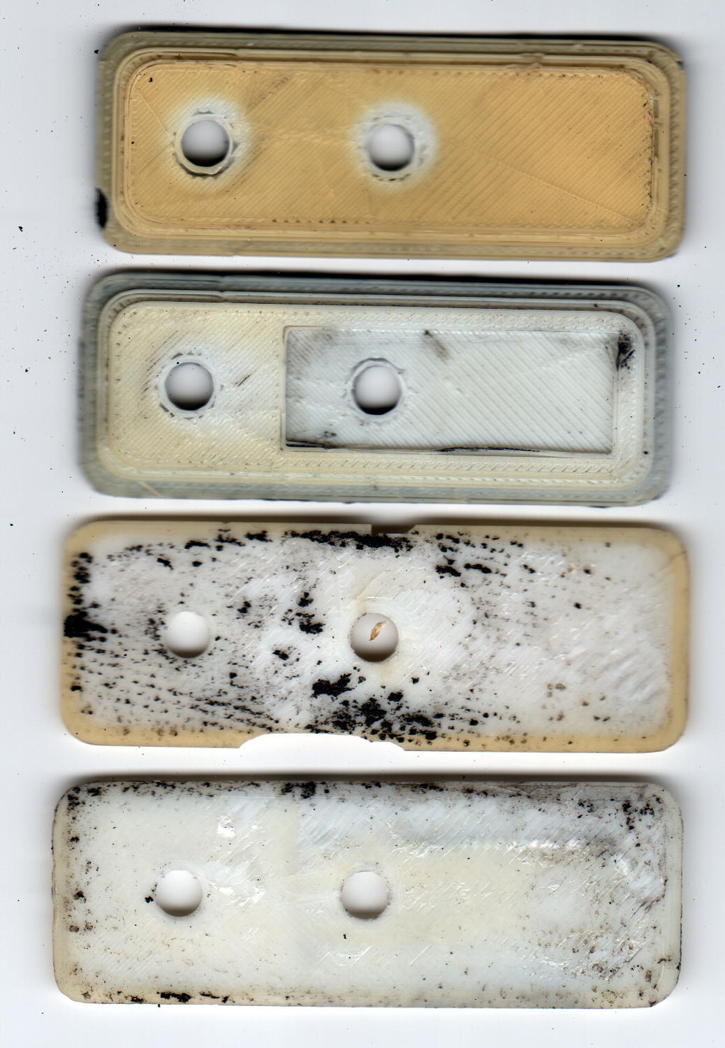
Over the course of those six years I’ve ridden about 6 × 2500 = 15000 miles, maybe more, maybe less. I can ride at 15 mph for a while, but 12 mph seems a more reasonable overall estimate, making for a bit over 1000 hours. Figure the bike spends that much time sitting outdoors at the far end of the ride and you’re looking at what 2000+ hours of sunlight does to ABS.
In addition to discoloration, the plates have become brittle, as shown in the chips in third one down, and permanently deformed due to the pressure of the nylon bolts compressing the black foam against the fairing.
A closer look at the top plate:
ABS Fairing Plates – 6 years – detail
My 3D print quality has improved a lot since then.
New plates of a different design are, as NASA puts it, “in work”.
The pix come from the new LiDE 120 scanner. It does a good job with the color, but has (for good reason) an essentially zero depth of field: if it’s not on the glass, it’s out of focus.
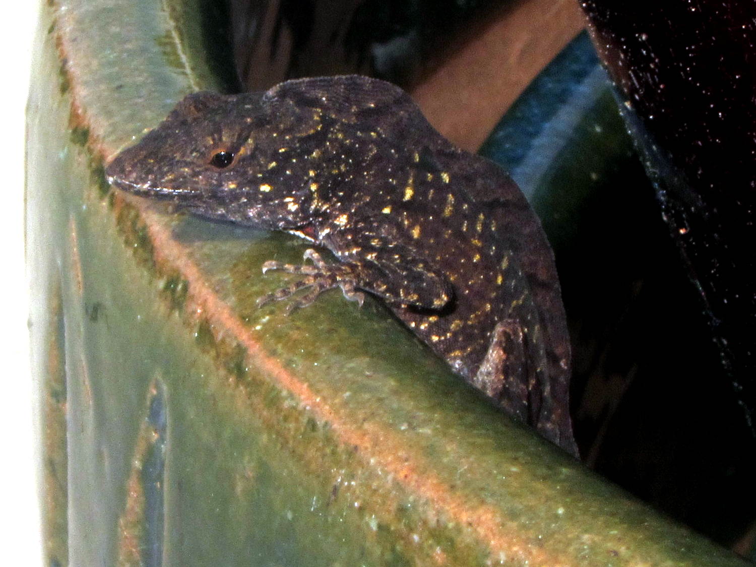
We found this critter keeping a watchful eye on the construction at Adams Fairacre Farms during our most recent grocery trip:
Mystery frilled lizard – detail
I think it’s an undocumented alien that entered the US stowed away in a tropical plant, because it was affixed to the array of ceramic pots outside their (open) greenhouse windows:
Mystery frilled lizard
To the best of my admittedly limited herpetological knowledge, none of our native lizards / geckos / whatever have such a distinctive dorsal frill / fin / ridge. I have no idea how to look the critter up, though.
We left it to seek its own destiny. Unless it’s a mated female (hard to tell with lizards), it’ll have a lonely life.
Perhaps it practices rishratha, which is entirely possible.
Anker LC40 flashlights can use either one lithium 18650 cell or an adapter holding three AAA cells. I now prefer 18650 cells, but they’re nigh onto 4 mm smaller than the flashlight ID and rattle around something awful.
The bottom trace comes from the 100× = 40 dB MAX4255 amplifier boosting the crystal output to a useful level. The fuzz on the waveform is actually the desired (off resonance) 60 kHz signal at maybe 30 mVpp, so the input is 300 µVpp.
The worst part of the OLED noise looks like 100 mVpp, for about 1 mVpp at the crystal output, call it +10 dB over the desired signal. Some high-pass filtering would help, but it’s easier to just shut the display off while measuring the crystal.
The top trace is the log amp output at (allegedly) 24 mV/dBV. The input bandwidth obviously extends way too low, as it’s neatly demodulating the input signal: the peaks correspond to both the positive and negative signal levels, so reducing the 1 µF input coupling caps will be in order.
In between those 100 Hz groups, the input signal shines through to the log amp output at the V1 cursor. The peak noise rises 290 mV above that, so the log amp thinks it’s 12 dB higher. Pretty close to my guesstimated 10 dB, methinks.
So, turning off the OLED should help a lot, which is feasible in this situation. If you must run the display while caring deeply about signal quality, you must devote considerably more attention to circuit construction quality.
Came up from the Basement Laboratory to find my Dell Optiplex 980 PC had failed, with the power button and diagnostic 1 + 3 LEDs blinking amber. They built it back in June 2010, so section 3 of the Dell reference applies, the power supply status LED on the back panel was off, and, going straight to the heart of matter, I popped the top, disconnected the internal power supply cables, and poked the power supply test button:
Optiplex 980 Power Supply – rear panel test button
… and it’s dead.
Inside, the system board sports a Mini-ATX power supply connector:
Optiplex 980 – Mini-ATX power connector
I originally hoped to swap a supply from an Optiplex 755 (also in a Small Form Factor case) residing on the recycle heap, but it has an ordinary ATX connector:
Optiplex 755 – ATX power connector
So I moved the 980’s SSD and dual-Displayport video card into the 755, fired that devil up, and … it worked!
With my desktop back in action, albeit somewhat slower, I popped the dead supply’s case by violating the Warranty Void If This Label Removed sticker to unscrew the last screw:
The cluster of caps on the upper right have bulged pressure-relief lids, like this:
Optiplex 980 – Bulging capacitor 1
And this:
Optiplex 980 – Bulging capacitor 2
And this:
Optiplex 980 – Bulging capacitor 3
None had ruptured, but they’re obviously feeling a bit nauseous.
Given the 980’s mid-2010 manufacturing date, this probably isn’t capacitor plague, just simple overheating from operating in a dead-air zone amid all those heatsinks and wires. Some of the Usual Unnamed Sources suggest overheating the capacitors is how manufacturers ensure their hardware doesn’t last forever, without being obvious about planned obsolescence; I’m loathe to ascribe to malice what can be explained by design desperation.
A Genuine Dell replacement supply from eBay ($25 delivered) came from yet another “small form factor” Dell chassis, so it isn’t quite the same size, lacks a supply test button / LED status light, and doesn’t quite fit:
Optiplex 980 – replacement supply misfit
Nothing a sheet metal nibbling tool can’t fix, though, given I haven’t developed a deep emotional attachment to the chassis. I gnawed off the left side of the frame and squared up the rim around the lower screw, after which the opening fit the supply pretty well, although the latching tab bent up from the bottom of the chassis didn’t quite engage the far end of the supply. No big deal: it’s not in a high-vibration environment.
The new-to-me supply also carries an ATX connector, but the eBay seller included a Mini-ATX adapter. Jamming the adapter + wires into the space available required concerted muttering, assisted by tucking the SSD under the DVD-RW drive. No pictures, as it’s a classic seven pounds in a five pound box situation.
There’s not much room on an AT26 / TF26 can for a readable label, unless one owns a metal-marking laser, but a simple bar code should let me identify each one:
Quartz Resonators – binary marking
The empty “0” slot down at the bottom will hold the crash-test dummy resonator I’ve been using to get the tester working.
The red-and-blue stripes from plain old fine-point Sharpie pens will rub off under duress, which I hope to avoid. After finishing up, I’m still not sure blue makes a better zero than red; you can make a convincing argument either way:
Binary marked AT26 Quartz Resonators
The bag allegedly contained 25 resonators, although I’m willing to agree the last one escaped into the clutter on or under the Electronics Workbench.