Ed Nisley's Blog: Shop notes, electronics, firmware, machinery, 3D printing, laser cuttery, and curiosities. Contents: 100% human thinking, 0% AI slop.
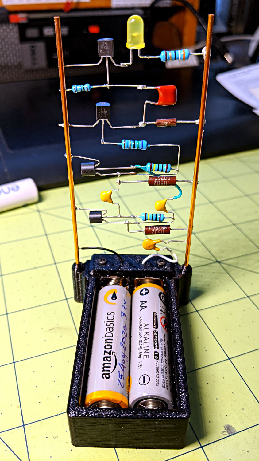
A fresh pair of alkaline AA cells at 3.2(-ish) V can’t light a Vf = 3 V blue LED with any authority, but I laid out an astable multivibrator circuit with a Piranha RGB LED to see how the colors looked:
Astable AA Alkaline – build test
Lighting all three LEDs at once doesn’t make much sense, although I did try it just for the amusement. Spoiler: red wins, even with more-or-less equal currents.
Red being the only LED color making any kind of sense meant the Piranha was overqualified for the job, so I replaced all that clutter with a simple 5 mm yellow LED:
Astable AA Alkaline – yellow
It’s shatteringly bright at 20 mA from fresh alkalines at 3.2 V and remains visible down to 1.8 V.
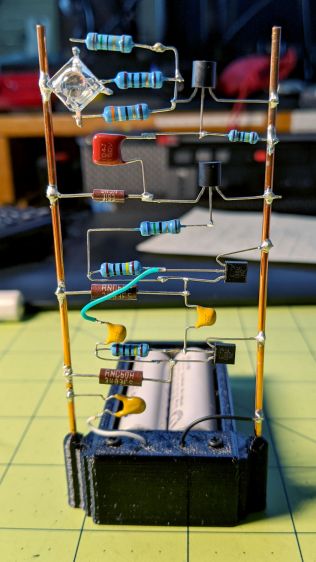
The original circuit schematic / layout doodle:
Astable wiring layout – Piranha RGB test
No surprise in any of this, as it’s why the discrete LM3909 circuitry happened, but it’s nice to have a simple LED atop some alkalines for show-n-tell. If, of course, show-n-tell events ever happen again …
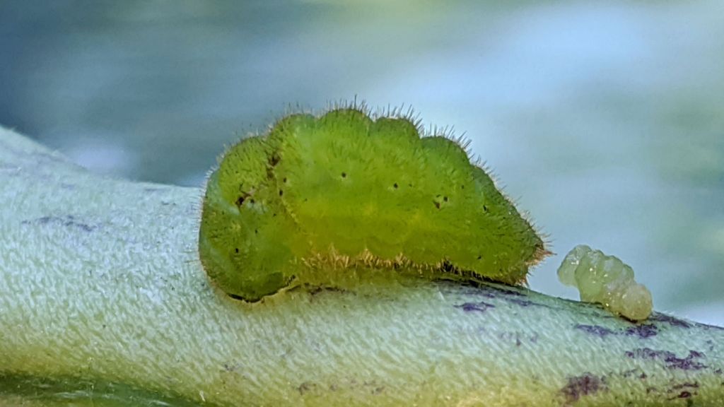
The lump on the right is frass, not a mini-me tagging along behind.
We had no clue what it might be when it grew up, but Google Lens suggested a Striped Hairstreak Butterfly caterpillar and, later that day (and for the first time ever!), we saw an adult Hairstreak fluttering on a goldenrod in the corner of the garden.
As with all caterpillars, you’d never imagine the adult butterfly. It seems they move their hind wings to make predators aim at the south end of a northbound butterfly …
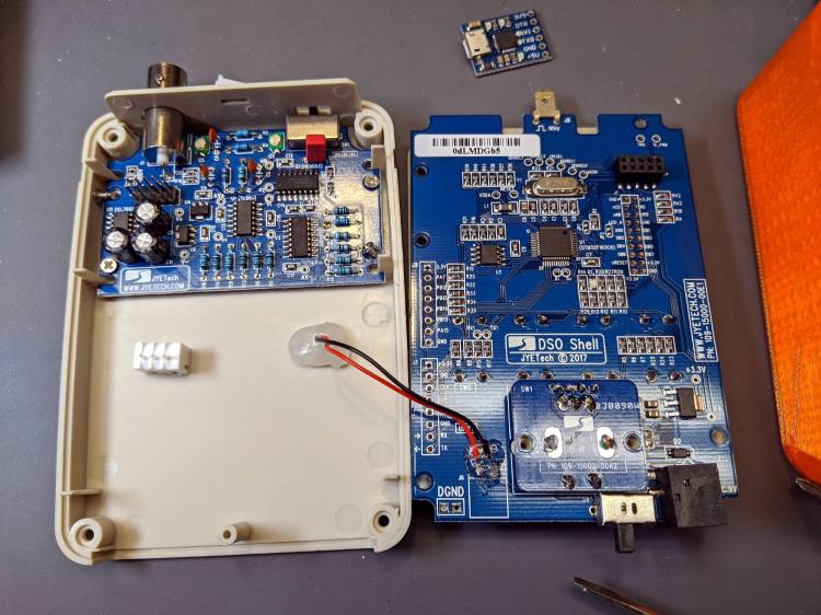
Taking all those pictures of the DSO150 screen reminded me it has a data dump function: press the V/Div and ADJ buttons to squirt configuration, measurements, and trace data from the TX pad on the main board, just in front of the red-black power wires hot-melt glued in place:
DSO150 USB serial adapter – interior
The picture shows the “before” stage, while I was figuring out where to carve another hole in the case.
NB: The 113-15001-111 DSO150 firmware version includes the serial output option, so you won’t need third-party firmware. Similarly, current PCBs bring the serial pins to neatly labeled header pads. You should refer to the JYETech DSO150 / DSO Shell product page for the details.
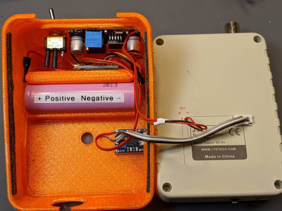
After all the cuttin’ and filin’ was done, it looked like this:
DSO150 USB serial adapter – exterior
The power switch on the back of the case (top of the picture) disconnects the lithium cell from the charge controller board (now tucked behind the battery) to eliminate any trickle current discharge. Charging the battery thus requires turning that switch on and turning the scope off with its own power switch (along its front edge). Capturing trace data requires having both switches on (duh), whereupon the scope’s normal operating current convinces the charge controller that the cell hasn’t reached full charge. Turn the scope off and, most likely, the controller will tell you the cell is fully charged.
An intro blurb squirts from the port at 115200 in good old 8N1 format when you turn the scope on:
It’s all in neatly comma-separated-value format, so you can slam it into a spreadsheet and have your way with it. Utilities also exist to capture the data, extract the values, and send them directly to GNUplot, etc.
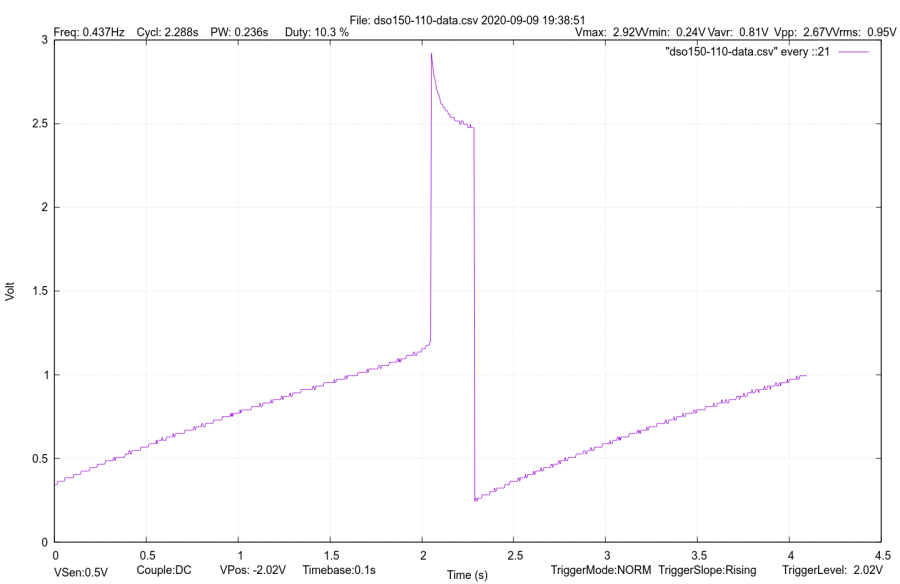
Like so:
DSO150 test image
If I expected to do a lot of that, I’d boldify the traces and embiggen the text, all of which is in the nature of fine tuning.
It’s hard to reproduce the beauty of the DSO150’s display, though:
DSO150 test image
The DSO150 remains pretty good for being the worst oscilloscope I’m willing to use …
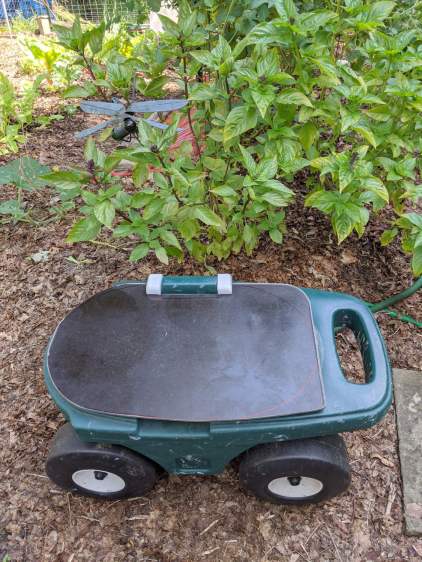
As expected, the plywood seat I put on the Step2 Garden Seat for Mary’s Vassar Farms plot lasted about a year before the wood rotted away around the screws. In the meantime, we’d acquired a stack of SiLite cafeteria trays, so we applied one to the cause of better seating:
Step2 Seat – tray variant
Various eBay listings value that slab of BakeliteMelamine up to $20, which is far more than Mary paid for the entire stack at a local tag sale. They also call that color “rich brown”, which is certainly better than what immediately came to mind when I saw them.
The stylin’ asymmetric design happened when I realized the squared-off handle end of the cart didn’t demand a rounded-off end of the seat. I cut off the raised tray rim before sketching the rounded outline using the rotted seat as a template; some of the sketch remains over on the right-front corner. A session with Mr Belt Sander put the remaining rim edges flush with the surface, no matter what the picture suggests.
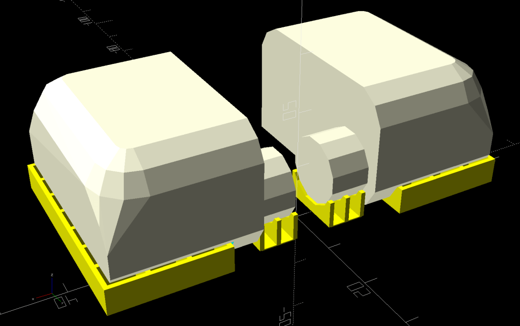
The tray being 2 mm thinner than the plywood, I tried printing the hinges in a different orientation with different built-in support:
Rolling Cart Hinges – solid model – build
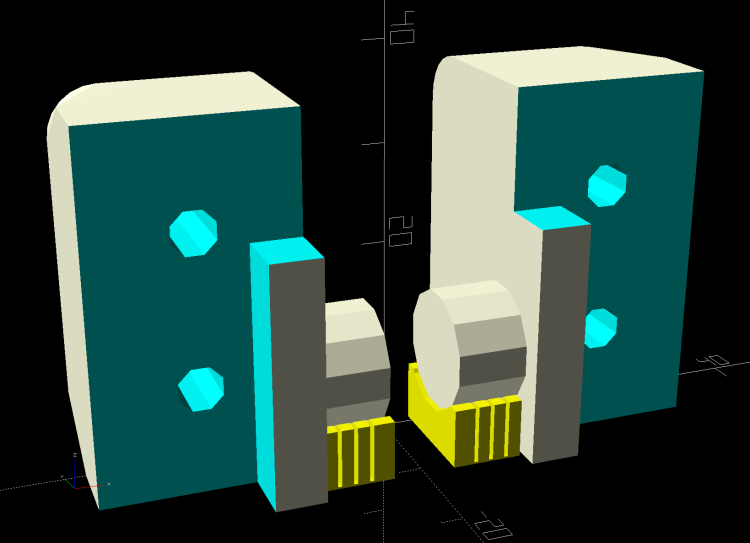
The perimeter threads pulled up far too much and, although fiddling with cooling would likely help, I think the original orientation was better:
Rolling Cart Hinges – solid model – bottom
Given that the post-apocalypse breakfast will be served on similar trays, the seat should survive for quite a while in the garden. We think the sun will convert the brown surface into a bun warmer; a coat of white paint may be in its future.
The original OpenSCAD code is still out there as a GitHub Gist.
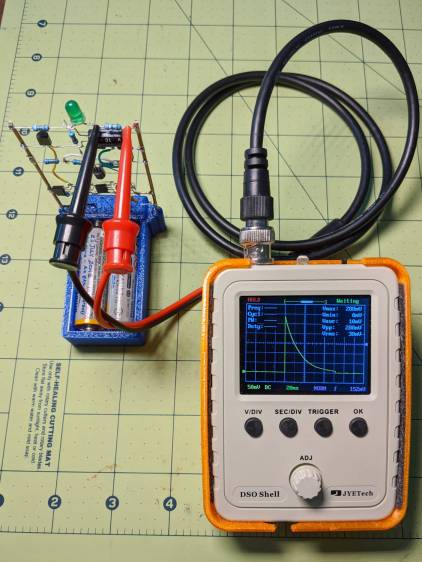
That’s a genuine JYETech DSO150 powered by an 18650 lithium cell and a boost converter set to 9 V. Make sure you get a genuine DSO150 from an authorized seller, rather than one of the myriad knockoffs; it doesn’t cost much more and tends to reward the right folks.
Anyhow, battery power means you can connect it directly across components to measure what would otherwise be a differential voltage:
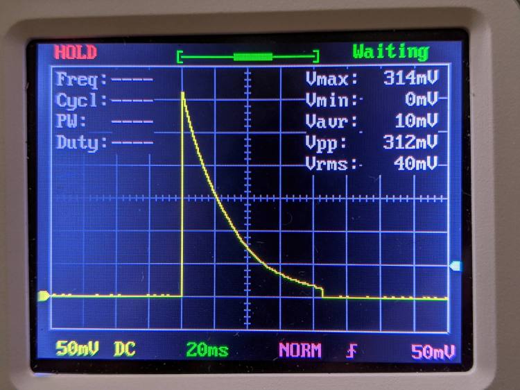
LM3909 – Darl Q1 3x Q2 – 1.5 V – R1 V – DSO150
That’s the voltage across R1, the 39 Ω LED ballast resistor in the discrete LM3909 circuit running from a 1.5 V supply. Divide the 314 mV peak by 39 Ω to get 8 mA of LED current.
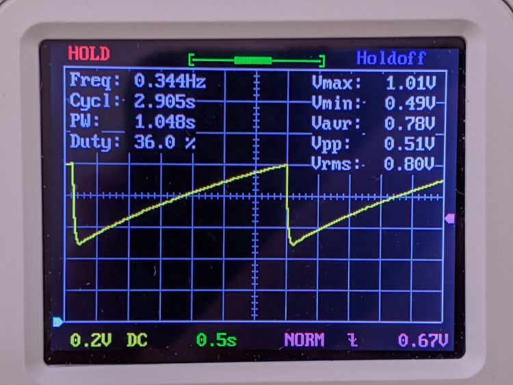
The voltage across C1, the timing and boost capacitor, looks like this:
LM3909 – Darl Q1 3x Q2 – 1.5 V – C1 V – DSO150
So the cap adds half a volt to the supply in order to put 2.0 V across the LED, which accounts for the relatively low current; the green LED has a forward drop of about 2.2 V at 20 mA and 1.9 V at µA-level current.
For completeness, the voltage across the LED:
LM3909 – Darl Q1 3x Q2 – 1.5 V – Green LED V – DSO150
So, yup, the LED really does see 2.0 V. I love it when the numbers work out.
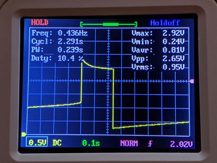
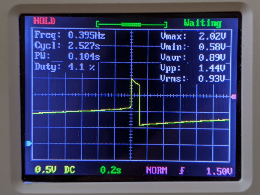
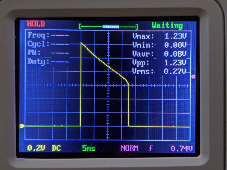
Crank the supply to 3 V and see this across R1:
LM3909 – Darl Q1 3x Q2 – 3.2 V – R1 V – DSO150
The LED current is now 1.23 V / 39 Ω = 33 mA.
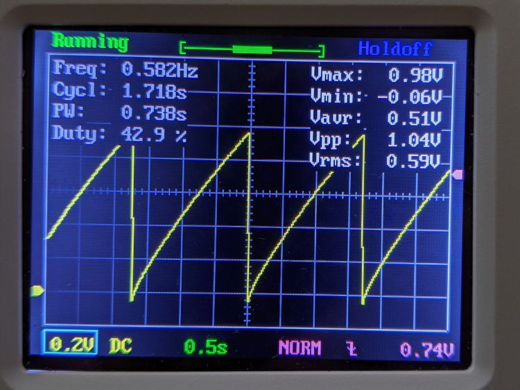
The capacitor just barely enters reverse charge:
LM3909 – Darl Q1 3x Q2 – 3.2 V – C1 V – DSO150
Pop quiz: what voltage to you expect to see across the LED?
I’ll leave further investigation to your imagination, but for low-frequency analog work, you can do worse than a DSO150.
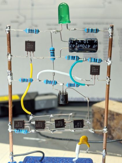
The four transistors across the bottom row let me test the simulation suggesting there’s no need for the 3× current gain mentioned in the App Note. Spoiler: future LM3909 circuits have the usual two-transistor mirror.
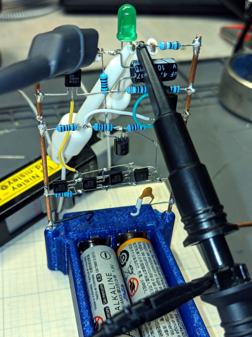
Adding some instrumentation required a bit of unsoldering and clip-lead action: to get the Tek current probe around the LED wiring:
LM3909 – Darl Q1 3x Q2 mirror – test setup
The voltage probe is across the LED, although you’ll also see the voltage across the capacitor and differential voltages measured properly with the common clip leads on the battery negative terminal. I unsoldered two of the mirror transistors after verifying a single mirror transistor can saturate Q3.
Removing the AA cells and feeding it with 3 V from a bench supply:
LM3909 – Darl Q1 1x Q2 – V on C1 – I 3V VCC 10 mA-div
The yellow trace is the voltage at the collector of Q3 = positive terminal of C1. The purple trace is the voltage at the LED cathode = negative terminal of C1. The fuzzy white trace is the difference of those two, showing C1 charges to about 1 V at the start of the LED flash. The white wedge over on the left marks the 0 V level, confirming the cap doesn’t enter reverse-charge territory during the flash.
The green LED produces a bright flash starting at 30 mA (bottom trace, 10 mA/div) for 15 ms. With 1 V on the cap, the LED + 39 Ω ballast resistor see nearly 4 V at the start of the pulse, because Q3 saturates around 20 mV.
Reducing the supply voltage to 1.5 V flattens the current and lengthens the flash to 35 ms:
LM3909 – Darl Q1 1x Q2 – V on C1 – I 1.5V VCC 10 mA-div
The cap still charges to 1 V between on-times, but the lower supply puts barely 2.5 V across the LED + 39 Ω resistor and the current peaks at 10 mA. The increased duration turns the flash into a blink.
It’s good enough, so AA alkalines should last quite a while.