Ed Nisley's Blog: Shop notes, electronics, firmware, machinery, 3D printing, laser cuttery, and curiosities. Contents: 100% human thinking, 0% AI slop.
I can’t tell whether the bollard stands in more concrete this time, but the gray pipe to the left of the gas meter is definitely new.
In round numbers, it took less than a week for the first impact, a week for the first repair, and … we shall see.
The white disk just behind it is a rat trap, with a subtle explanatory sign directly above it. The building has three such traps, so they’re apparently trying to stay ahead of a known problem; we find similar traps around most commercial establishments.
The fuzzy felt feet on the lift chairs raised them enough to slide both floor lamp bases underneath with the backs in the upright state, but reclining the chair with the light more than halfway back along the side of the chair crunched the lamp base.
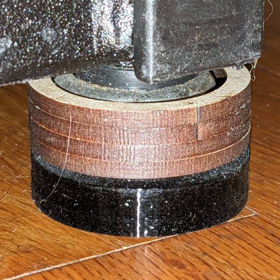
Rather than print taller fuzzy feet, which takes a long time, I knocked out two quartets of laser-cut risers:
Lift Chair Foot Riser – installed
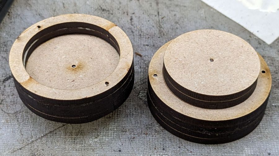
They’re six layers of 3 mm MDF or plywood:
Lift Chair Foot Riser – assembled
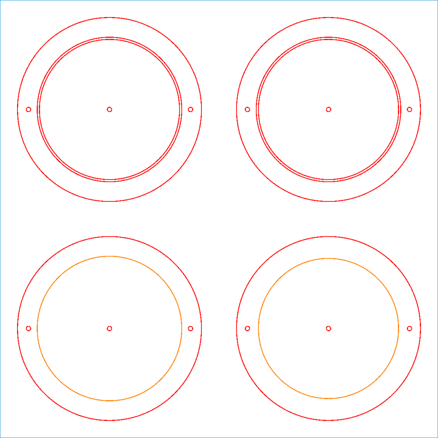
The LightBurn layout makes one riser:
Lift Chair Feet Extenders – LB layout
The upper two discs become two rings and two pads, with the lower two disks forming the middle layers. The ring ID clears the chair foot and the pad OD fits into the existing printed fuzzy felt foot. The two cuts making that happen leave the thinnest imaginable ring of MDF in place.
The tiny circles cut holes for 11 mm snippets of 1.1 mm hard steel wire aligning the layers:
Lift Chair Foot Riser – locating pins
Assembly sequence:
Tap two pins into a ring
Butter the ring with yellow wood glue
Slide the other ring over the pins
Butter
Slide a disk over the pins
Drive a pin into a pad
Butter
Slide the other pad over the pin
Butter
Slide a disk over the pin atop the pads
Butter one of the disks
Slide the disks together over all three pins
Tap all pins below their surface
Make two and clamp them together to ensure everything sticks firmly.
Repeat to make four risers
Install, recline, and enjoy not hearing a mysterious crunch from the lamp base.
The alert reader will note the 6 mm stack of two pads leaves a slight gap above the printed foot. Turns out the recess is 5 mm deep and I decided to just live with a 1 mm gap down there.
The IR sensor on the under-cabinet LED lights I installed half a dozen years ago became increasingly flaky. Its wall wart power supply was on the hot side of uncomfortably warm, so I had an obvious culprit.
The data plate says it’s UL Listed, which is comforting:
Flypower LED wart – data plate
The open-circuit output of a 12 VDC power supply should not look like this:
FlyPower 12V 1A – no load
The horizontal scale is 100 ms/div, so those ramps seem much more languid than you might expect from a 60 Hz wall wart.
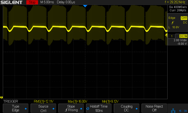
Adding a 16 Ω load to draw maybe 750 mA got its attention:
FlyPower 12V 1A – 16ohm load
The average may be 12 V with too-large dips at the expected 120 Hz, but looky at all the hash riding the output!
No wonder the IR sensor was having such a hard time. When the LEDs are off the voltage ramps between 16 and 5 V. When it eventually turns on the supply has impossible noise levels.
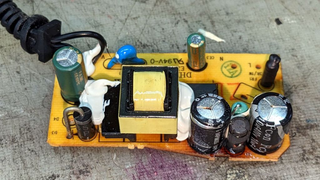
So I cracked the case and extracted the electronics:
Flypower LED wart – components
Those caps over there on the left rear don’t look healthy, do they?
Flypower LED wart – failed caps
No. No, they don’t and you shouldn’t be able to see the wiring inside the inductor between them, either.
Probing the Box o’ Wall Warts produced a similar-ish wart that only required harvesting and splicing the teeny coax plug from the failed adapter to put the LED strips back into normal operation.
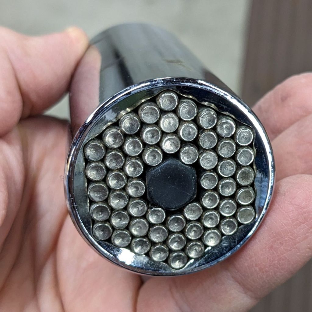
Being that type of guy, I wanted to salvage a loooong square-head bolt from the utility pole stub formerly holding up the mailboxes, which would require a few gazillion turns of its square head with the Adjustable Elephant Wrench. After verifying I couldn’t just hammer the mumble thing through the pole, I gave a few turns of the Universal Socket on a ratchet:
Universal Socket Wrench
It’s intended for goobered hex heads up to 1-¼ inch, but the pins slide down around pretty much anything that sticks out and jam against the shell, so it’s handy for those last-ditch extraction events.
After verifying doing this by hand would occupy me until just before the heat death of the universe, I followed Mad Phil’s signal connector adage: “If you can get to BNC, you can get to anything.”
Some rummaging produced this unsteady mechanical ziggurat:
Universal Socket to quarter-inch hex – adapter stack
From bottom to top:
Universal Socket with ½ inch square drive socket
1/2 inch square drive to ¾ inch hex
19 mm (close enough to ¾ inch) 12-point socket to ⅜ inch square drive socket
⅜ inch square drive to ¼ inch square drive socket
¼ inch square drive to ¼ inch hex drive
Then stick the teeny end into the hand drill, rig engines for reverse running, and whine away on that bolt, which obligingly backed right out.
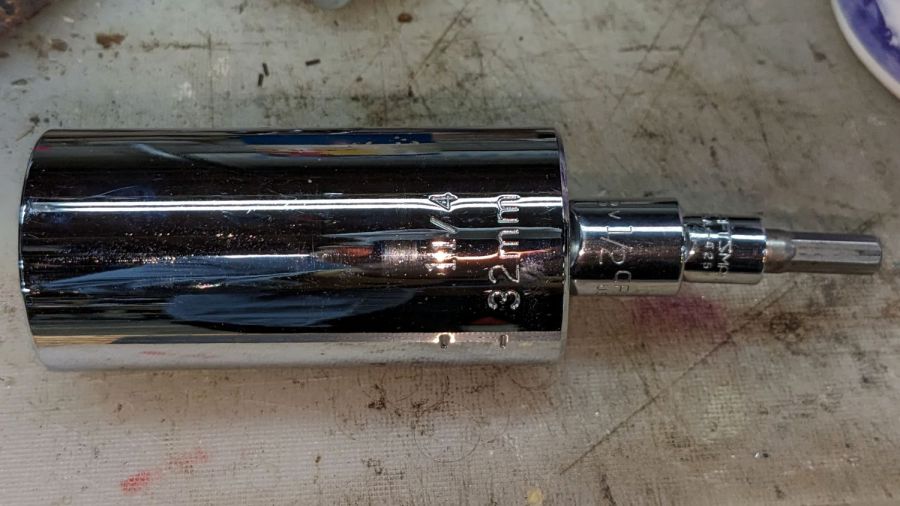
After the fact, I found the obviously missing ¼ to ½ inch square drive adapter hiding in the Drawer o’ Sockets:
Universal Socket – short adapter stack
Which doesn’t make any more sense, but is less likely to fall apart under normal use.
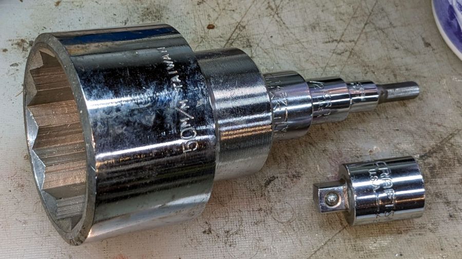
Aaaaand one more adapter makes this possible:
Improper square drive adapter stack
That’s a 50 mm socket turned by ¼ inch hex drive in four easy steps, although I’m reasonably sure it still won’t get the idler bogies off my armored personnel carrier.
The stray adapter steps down from ½ square to ⅜ square, should a need for a breaker bar occur during eyeball surgery.
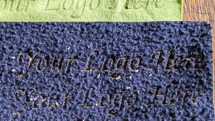
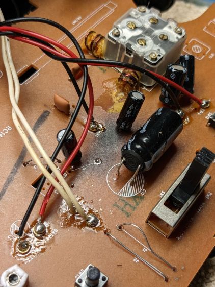
A power failure apparently pushed the ancient RCA alarm clock over the edge into a mode where it ignored its pushbuttons and displayed a time based on a hitherto unknown exoplanet. Popping the case revealed it’s been simmering in its own juices for quite a while:
RCA Alarm Clock – PCB overheat
There’s nothing obviously scorched on the underside of the PCB, although a large SMD resistor might be the source of the problem.
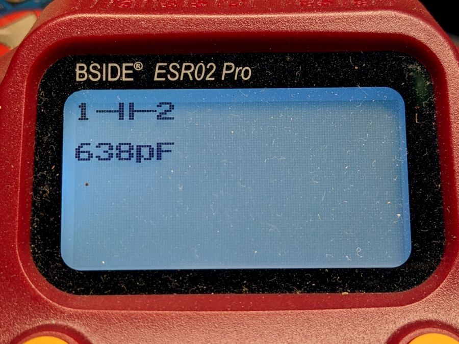
Having been around this block a few times, I unsoldered that big electrolytic cap with its guts protruding from the overwrap:
RCA Alarm Clock – failed cap value
Nope, that’s not really an electrolytic cap any more.
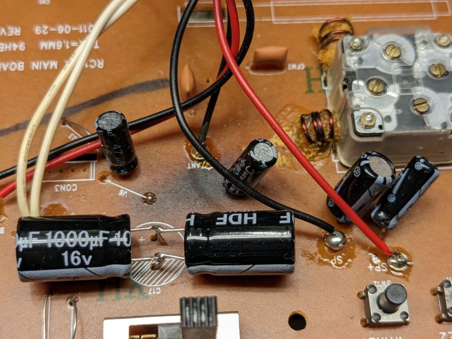
Lacking a 2200 µF cap of suitable voltage rating, but knowing cap tolerances allow for considerable windage, this worked out well enough:
RCA Alarm Clock – replacement caps
Two smaller caps measuring on the low side of OK now reside in the e-waste box.
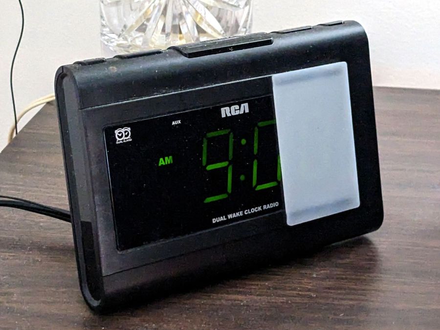
The white diffuser over the last digit improves it in ways I do not profess to understand, but am pleased to implement:
RCA Alarm Clock – in place
It’s held in place by two strips of LSE tape to see how it reacts to prolonged shear force, no matter how gentle.
Combining a new mailbox with a post and an old mailbox I had on hand, upcycling some scrap wood, then sticking on a few digits and a seasonal decoration found on a walk, should shake loose the mail currently stuck in the USPS delivery system:
Mailboxes – south view
That’s an Extra Large mailbox, suitable for most packages arriving by USPS, and dwarfing the ordinary mailbox on the north side:
The boxes sit on slabs harvested from an old door and screwed to two layers of Chinese plywood from the laser cutter’s shipping crate, all unpainted / untreated interior-grade (at best) wood cut with a circular saw. My assumption is they’ll last long enough for the purpose and, not having formed a deep emotional bond with them, I won’t feel too bad when the assembly gets pulverized.
The whole affair sports a rakish tilt toward the street, in the hope of encouraging rainwater to run off, rather than soak in, but I fully expect the untreated plywood to act as a sponge and delaminate / curl / splay in a spectacular & amusing fashion.
The pale rectangle across the vertical post is a (laser cut!) Chinese plywood plate intended to hold the crossbar together. The vertical and horizontal posts meet in a simple cross lap joint that surely wasn’t intended to support nearly so much weight: reinforcement seems appropriate.