A power failure apparently pushed the ancient RCA alarm clock over the edge into a mode where it ignored its pushbuttons and displayed a time based on a hitherto unknown exoplanet. Popping the case revealed it’s been simmering in its own juices for quite a while:
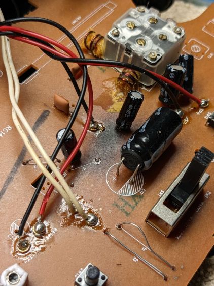
There’s nothing obviously scorched on the underside of the PCB, although a large SMD resistor might be the source of the problem.
Having been around this block a few times, I unsoldered that big electrolytic cap with its guts protruding from the overwrap:
Nope, that’s not really an electrolytic cap any more.
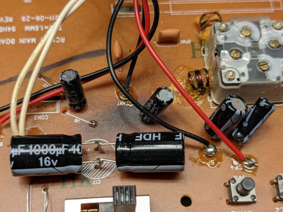
Lacking a 2200 µF cap of suitable voltage rating, but knowing cap tolerances allow for considerable windage, this worked out well enough:
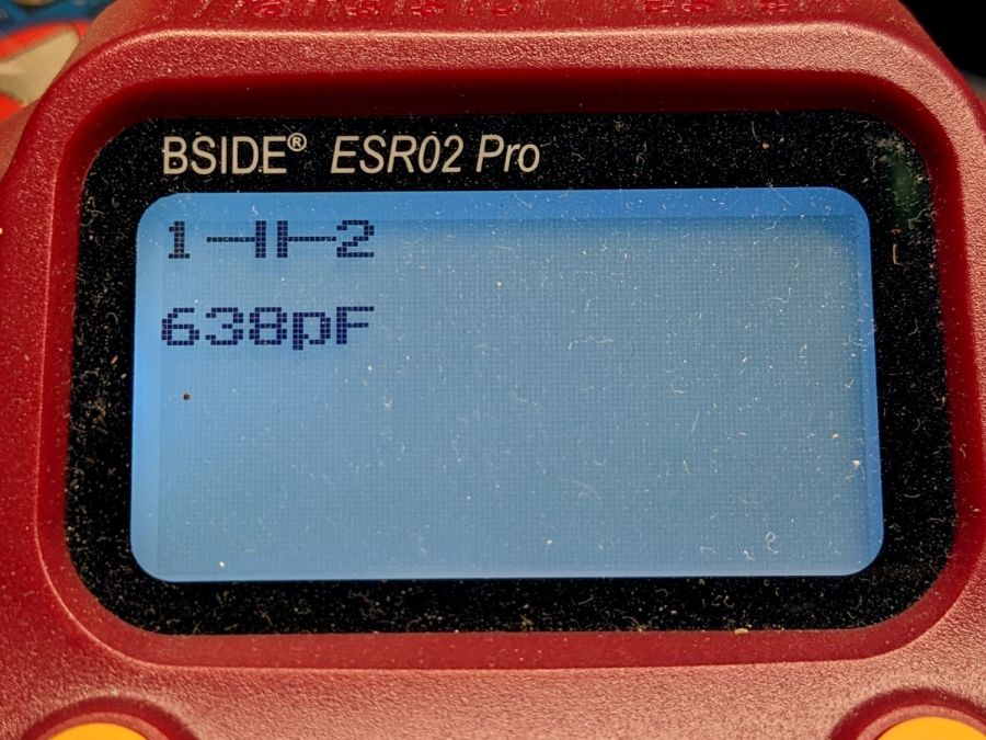
Two smaller caps measuring on the low side of OK now reside in the e-waste box.
The white diffuser over the last digit improves it in ways I do not profess to understand, but am pleased to implement:
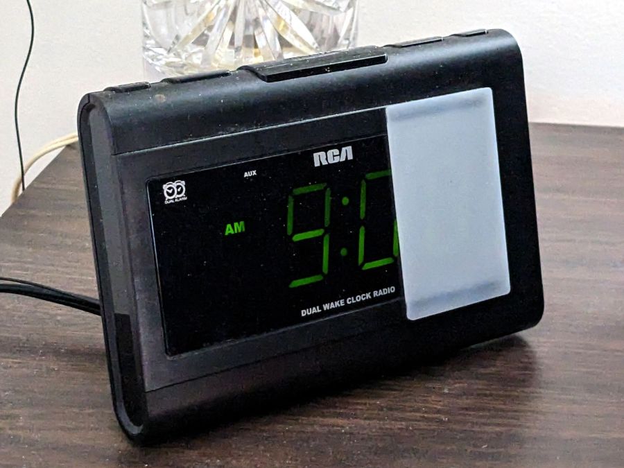
It’s held in place by two strips of LSE tape to see how it reacts to prolonged shear force, no matter how gentle.

Comments
5 responses to “RCA Alarm Clock: Recapping”
I have my students build a little alarm clock kit (based on AT89C2051) for soldering training, and covering the 7 segment display with red tail light repair tape vastly increases the readability. Perhaps your diffuser improves things for the same reasons?
I was astonished by how much a simple red filter improves (red) LED readability; something to do with signal-to-noise ratio. [grin]
This one started as a folded tissue draped over the clock to get rid of the last two of those already-dimmed digits. I suggested something less prone to being blown away by passing bodies and, well, here we are.
I need to delve into one or two stereo preamps. The older one had the potted(!) phono pre-preamp module die 25 years ago, and that was replaced with suitable ICs from National Semi. (Remember them?)
This time, the potted main preamp died, and I suppose for a unit over 40 years old, it might not be worth coming up with a replacement.
Except: the preamp I bought to replace it works fine in summer months, but winter in the barn means temperatures in the 30s. All is good from the line-level input to the line-level tape out, but after that, it’s seriously distorted. (Discovered after the warranty ran out, all hail to Murphy.)
I need to see if the ancient HP 1MHz scope is working, or to build the one like you have. My SWAG is that a cap on that section of the PC board is in bad shape.
This might be a good excuse to get an ESR meter, too. And possibly some other test equipment. [grin]
My morning coffee mind cannot fathom the benefit of the 10-minute quantum, and I’m unsure if I want to know.
It makes perfect sense in the deep hours of the night, far from the light of reason. So I am told and I am content with that knowledge.