The fairing mount must aim the flashlight generally parallel to the ground and slightly toed-in toward the bike’s frame, ideally holding the ball more-or-less in the center of its adjustment range. I eyeballed a protractor for the initial estimates and got it reasonably close on the third try:
One more skilled in math than I could define a matrix transformation between the solid model’s XYZ coordinate space and the fairing’s XYZ space, then figure the reverse transformation allowing you to convert real-world angles back to the model’s space. I winged it by setting up adjustments to rotate the ball clamp ring on all three axes around its center:
| translate([-BracketHoleOC,0,0]) | |
| PlateBlank(); | |
| translate([Shift,0,ClampOD/2]) | |
| rotate([-Roll,ToeIn,Tilt]) | |
| intersection() { | |
| translate([0,0,-ClampOD/2]) | |
| cube([2*ClampOD,2*ClampOD,ClampOD],center=true); | |
| BallClamp(); | |
| } |
Lifting the ring upward by half its OD leaves it tangent to the XY plane, firmly embedded in the blank fairing clamp plate, and, through the magic of 3D printing, looking like it grew there.
In practice, aligning the ring isn’t too difficult. Align an eyeball along each of the mount’s axes, center a protractor on the ball with it perpendicular to the line of sight, rotate it so the baseline is level / straight-ahead / crosswise, read off the angle, then type it in. Of course you’ll get the sign wrong at least once.
For a given set of those angles, the mount looks like this:

You can determine by inspection there’s no way to orient the shape for E-Z building, although putting the plate flat on the platform has a lot to recommend it.
The outside being a spherical section, the overhangs will curl upward, so (as with the ball around the flashlight) rows of fins anchor the perimeter threads:

The fins are just under two threads wide to eliminate any possible infill, with a simple sphere chopping their tops to fit just inside the clamp:
| if (MountSupport) { // anchor outer corners during worst overhang | |
| RibWidth = 1.9*ThreadWidth; | |
| SupportOC = 0.1 * ClampLength; | |
| difference() { | |
| rotate([0,0,Tilt]) | |
| translate([Shift + 0.3,0,0]) | |
| for (i=[-4.5,-2.5,0,2.0,4.5]) | |
| translate([i*SupportOC – 0.0,0,(ClampThick + Plate[2])/2]) | |
| cube([RibWidth,0.8*ClampOD,(ClampThick + Plate[2])],center=true); | |
| # translate([Shift,0,ClampOD/2]) | |
| rotate([-Roll,ToeIn,Tilt]) | |
| sphere(d=ClampOD – 2*ThreadWidth,$fn=NumSides); | |
| } | |
| } |
Slic3r built support structures under the overhanging screw bosses:

It also added weird little towers that don’t come close to touching the clamp’s lower surfaces, which is why I added those fins. The automatic support should extend to one thread thickness from the bottom surface, but that’s a hard calculation to make for a spherical section represented by tesselating triangles.
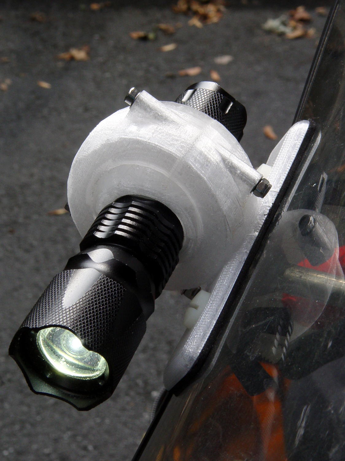
After a few test rides, the whole affair seems to be both holding together and holding the flashlight, so it’s good enough for now. A twilight ride around the block may be needed for better aiming, though.

Comments
One response to “Tour Easy Daytime Running Light: Fairing Mount”
[…] more test rides, the flashlight fairing mount works […]