If I were selling those brackets, I’d be rich:
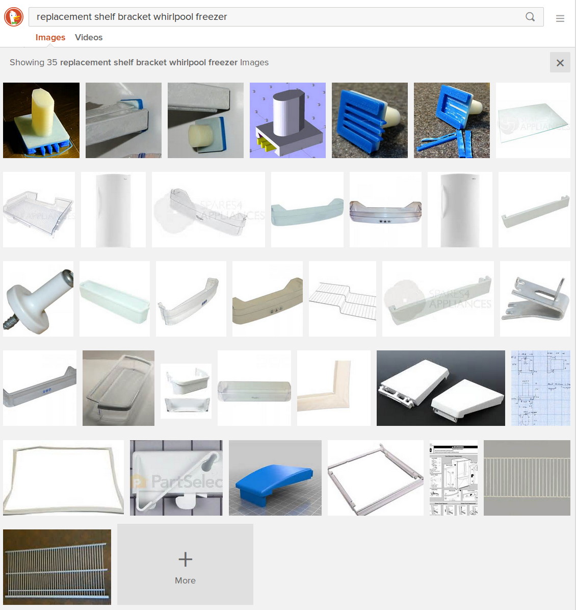
Now, that looks like Search Engine Optimization it is to die for! Google will give you a different set of pictures, but I own that all-important top row.
Alas, anybody can just print their own…
The Smell of Molten Projects in the Morning
Ed Nisley's Blog: Shop notes, electronics, firmware, machinery, 3D printing, laser cuttery, and curiosities. Contents: 100% human thinking, 0% AI slop.
Using and tweaking a Makerbot Thing-O-Matic 3D printer
If I were selling those brackets, I’d be rich:
Now, that looks like Search Engine Optimization it is to die for! Google will give you a different set of pictures, but I own that all-important top row.
Alas, anybody can just print their own…
Mary recently learned that large spools of thread have a cross-wound lay that should feed over the end, not from the side as do ordinary stack-wound spools. So I built a right-angle adapter that fits over the not-quite-vertical spool pin on the sewing machine and aims directly at the thread tensioner:

The solid model shows off the fluted rod that passes through the spool:

It’s more impressive from the other end:
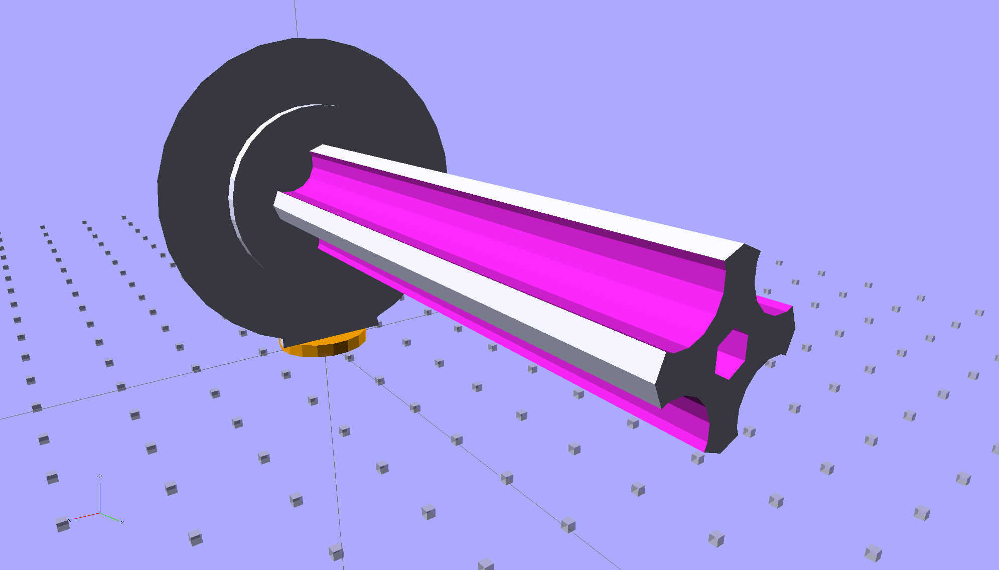
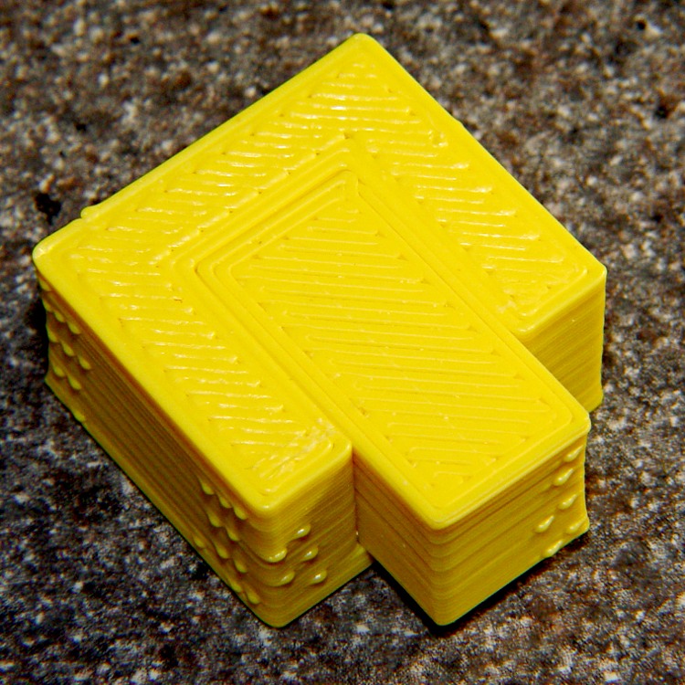
The first pass at the rod had six flutes, but that seemed unreasonably fine; now it has four. The round base on the rod provides more griptivity to the platform while building and has enough space for the two alignment pins that position it in the middle of the dome:

The dome gets glued to the rod base plate:

The spool pin hole is a snug fit around the pin on the sewing machine, because otherwise it would tend to rotate until the spool pointed to the rear of the machine. The fluted rod is a snug friction fit inside the (cardboard) spool. Some useful dimensions:
I had all manner of elaborate plans to make an expanding fluted rod, but came to my senses and built the simple version first. If that rod isn’t quite big enough, I can build another adapter, just like this one, only slightly larger. The source code includes a 0.5 mm taper, which may suffice.
Back in the day, shortly after the Thing-O-Matic started producing dependable results, one of the very first things I made was a simple adapter to mount large spools on the pin in the most obvious way:
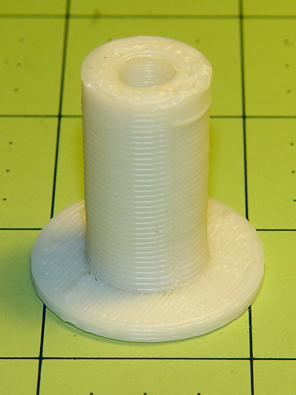
Now we all know better than that, my OpenSCAD-fu has grown stronger, and the M2 produces precise results. Life is good!
The OpenSCAD source code:
// Large thread spool adapter
// Ed Nisley - KE4ZNU - August 2014

Layout = "Show";			// Build Show Spindle Spool

Gap = 10.0;					// between pieces in Show

//- Extrusion parameters must match reality!
//  Print with 4 shells and 3 solid layers

ThreadThick = 0.20;
ThreadWidth = 0.40;

HoleWindage = 0.2;			// extra clearance

Protrusion = 0.1;			// make holes end cleanly

AlignPinOD = 1.70;			// assembly alignment pins: filament dia

function IntegerMultiple(Size,Unit) = Unit * ceil(Size / Unit);

//----------------------
// Dimensions

LEN = 0;											// subscripts for cylindrical objects
ID = 1;
OD = 2;

Spindle = [40.0,5.0,14.0];							// spool spindle on sewing machine
Spool = [70.0,16.0,27.0];							// spool core

Taper = 0.50;										// spool diameter increase at base

CottonRoll = [65.0,Spool[OD],45.0];					// thread on spool

Mount = [Spindle[LEN],(Spindle[ID] + 4*ThreadWidth),1.0*Spool[ID]];

Flutes = 4;
Flange = [2.0,Spool[OD],Spool[OD]];

ScrewHole = [10.0,4.0 - 0.7,5.0];					// retaining screw

PinOC = Spool[ID]/4;								// alignment pin spacing

//----------------------
// Useful routines

module PolyCyl(Dia,Height,ForceSides=0) {			// based on nophead's polyholes

  Sides = (ForceSides != 0) ? ForceSides : (ceil(Dia) + 2);

  FixDia = Dia / cos(180/Sides);

  cylinder(r=(FixDia + HoleWindage)/2,
           h=Height,
           $fn=Sides);
}

module ShowPegGrid(Space = 10.0,Size = 1.0) {

  RangeX = floor(100 / Space);
  RangeY = floor(125 / Space);

	for (x=[-RangeX:RangeX])
	  for (y=[-RangeY:RangeY])
		translate([x*Space,y*Space,Size/2])
		  %cube(Size,center=true);

}

//- Locating pin hole with glue recess
//  Default length is two pin diameters on each side of the split

module LocatingPin(Dia=AlignPinOD,Len=0.0) {

	PinLen = (Len != 0.0) ? Len : (4*Dia);

	translate([0,0,-ThreadThick])
		PolyCyl((Dia + 2*ThreadWidth),2*ThreadThick,4);

	translate([0,0,-2*ThreadThick])
		PolyCyl((Dia + 1*ThreadWidth),4*ThreadThick,4);

	translate([0,0,-(Len/2 + ThreadThick)])
		PolyCyl(Dia,(Len + 2*ThreadThick),4);

}

//----------------------
// Spindle

module SpindleMount() {

	render(convexity=4)
	difference() {
		union() {
			resize([0,0,Mount[OD]])							// spool backing plate
				translate([0,CottonRoll[OD]/2,0])
					sphere(d=CottonRoll[OD],center=true);
			translate([0,CottonRoll[OD]/4,0])				// mounting post
				rotate([90,0,0])
					cylinder(d=Mount[OD],h=CottonRoll[OD]/2,center=true);
		}

		translate([0,(2*Mount[LEN] - Protrusion),Mount[OD]/4])				// punch spindle hole
			rotate([90,0,0])
//				PolyCyl(Spindle[ID],2*Mount[LEN],6);
				cylinder(d=Spindle[ID],h=2*Mount[LEN],$fn=6);

		for (i=[-1,1]) {									// punch alignment pin holes
			translate([i*PinOC,CottonRoll[OD]/2,0])
					LocatingPin(Len=Mount[OD]/3);
		}

		translate([0,0,-CottonRoll[OD]])					// remove half toward spool
			cube(2*CottonRoll[OD],center=true);
	}

}

//----------------------
// Spool holder

module SpoolMount() {

	difference() {

		union() {

			translate([0,0,(Flange[LEN] - Protrusion)])
				difference() {
					cylinder(d1=(Spool[ID] + Taper),d2=Spool[ID],h=Spool[LEN],$fn=2*Flutes);						// fit spool ID

					for (a=[0 : 360/Flutes : 360-1])						// create flutes
						rotate(a + 180/Flutes)
							translate([Spool[ID]/2,0,-Protrusion])
								rotate(180/16)
								cylinder(r=Spool[ID]/4,h=(Spool[LEN] + 2*Protrusion),$fn=16);

					translate([0,0,(Spool[LEN] - ScrewHole[LEN])])			// punch screw hole
						PolyCyl(ScrewHole[ID],(ScrewHole[LEN] + Protrusion),6);

				}
			cylinder(d=Flange[OD],h=Flange[LEN]);							// base flange
		}

		for (i=[-1,1])												// punch alignment pin holes
			translate([0,i*PinOC,0])								//  ... orients solid flange up
					LocatingPin(Len=Flange[LEN]);
	}

}


ShowPegGrid();

if (Layout == "Spindle") {
	SpindleMount();
}
if (Layout == "Spool") {
	SpoolMount();
}

if (Layout == "Show") {
	translate([0,Mount[OD]/4,2.0]) {
		rotate([90,0,0])
			SpindleMount();
		translate([0,Gap,CottonRoll[OD]/2])
			rotate([-90,0,0]) rotate(90)
				SpoolMount();
	}
	color("Orange") {
		translate([0,0,2])
			cylinder(d=Spindle[ID],h=Spindle[LEN],$fn=6);
		cylinder(d=Spindle[OD],h=2.0,$fn=18);
	}

}

if (Layout == "Build") {
	translate([-5,0,0])
		rotate(90)
			SpindleMount();
	translate([Flange[OD]/2,0,0])
			SpoolMount();
}
During one of my recent presentations, somebody asked about the accuracy of 3D printed parts, which reminded me of another member of Coasterman’s Essential Calibration Set: the perimeter width/thickness test block. Back in the day, calibrating the extruder meant getting the actual ratio of the thread width to its thickness to match the ideal value you told Skeinforge to use; being a bit off meant that the final dimensions weren’t quite right.
But when I got it right, the Thing-O-Matic printed a test block with considerable success, despite the horrible retraction zittage:
Alas, feeding the STL to Slic3r showed that it was grossly non-manifold, and none of the automated repair programs produced good results. Turns out it’s an STL created from a Sketchup model, no surprise there, and the newer slicers seem less tolerant of crappy models.
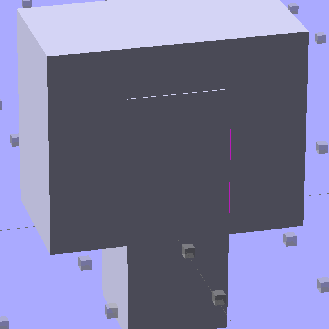
Sooo, here’s a new version built with OpenSCAD:

You get three blocks-and-plugs at once, arranged in all the useful orientations, so you can test all the fits at the same time. They come off the platform about like you’d expect:

I tweaked the code to make the plugs longer than you see there; the short ones were mighty tough to pry out of those slots.
I ran the plugs across a fine file to clean the sides, without removing any base material, and the plugs fit into the slots with a firm push. I’d do exactly the same thing for a CNC milled part from the Sherline, plus breaking the edges & corners.
The plugs doesn’t fit exactly flush in the recesses for the two models on the right side of that first image, because the edges and corners aren’t beveled to match each other. It’s pretty close and, if it had to fit exactly, you could make it work with a few more licks of the file. The left one, printed with the slot on the top surface, fits exactly as flush as the one from the Thing-O-Matic.
Of course, there’s a cheat: the model allows 0.1 mm of internal clearance on all sides of the plug:
The outside dimensions of all the blocks and plugs are dead on, within ±0.1 mm of nominal. You’d want to knock off the slight flange at the base and bevel the corners a bit, but unless it must fit inside something else, each object comes off the platform ready to use.
Feel free to dial that clearance up or down to suit your printer’s tolerances.
The OpenSCAD source code:
// Fit test block based on Coasterman's perimeter-wt.stl
//	http://www.thingiverse.com/thing:5573
//	http://www.thingiverse.com/download:17277
// Ed Nisley - KE4ZNU - May 2014

Layout = "Show";

//- Extrusion parameters must match reality!
//  Print with 2 shells and 3 solid layers

ThreadThick = 0.20;
ThreadWidth = 0.40;

Protrusion = 0.1;			// make holes end cleanly

function IntegerMultiple(Size,Unit) = Unit * ceil(Size / Unit);

//----------------------
// Dimensions

Clearance = 0.1;

PlugSize = [10.0,10.0,25.0];
BlockSize = [25.0,13.0,20.0];

PlugOffset = 10.0;

//----------------------
// Useful routines

module ShowPegGrid(Space = 10.0,Size = 1.0) {

  RangeX = floor(100 / Space);
  RangeY = floor(125 / Space);

	for (x=[-RangeX:RangeX])
	  for (y=[-RangeY:RangeY])
		translate([x*Space,y*Space,Size/2])
		  %cube(Size,center=true);

}

module Block() {
	difference() {
		translate([0,0,BlockSize[2]/2])
			cube(BlockSize,center=true);
		translate([0,PlugSize[1] - PlugSize[1]/2 - BlockSize[1]/2,-PlugOffset])
			Plug(Clearance);
	}
}

module Plug(Clear = 0.0) {
	minkowski() {
		translate([0,0,PlugSize[2]/2])
			cube(PlugSize,center=true);
		if (Clear > 0.0)
			cube(Clear,center=true);
	}
}

//----------------------
// Build it

ShowPegGrid();

if (Layout == "Block")
	Block();

if (Layout == "Plug")
	Plug();

if (Layout == "Show") {
	Block();
	translate([0,PlugSize[1] - PlugSize[1]/2 - BlockSize[1]/2,-PlugOffset])
		Plug();
}

if (Layout == "Build") {
	Block();
	translate([0,-15,0])
		Plug();

	translate([-30,0,0]) {
		translate([0,-BlockSize[1]/2,BlockSize[1]/2])
			rotate([-90,0,0])
				Block();
		translate([-PlugSize[2]/2,-15,PlugSize[0]/2])
			rotate([0,90,0])
				Plug();
	}

	translate([30,0,0]) {
		translate([0,0,BlockSize[2]])
			rotate([180,0,180])
				Block();
		translate([-PlugSize[2]/2,-15,PlugSize[1]/2])
			rotate([90,0,90])
				Plug();
	}

}
The Boneheads Raven Skull demo came out reasonably well, albeit in a reduced size, on the Squidwrench Frank-o-Squid:

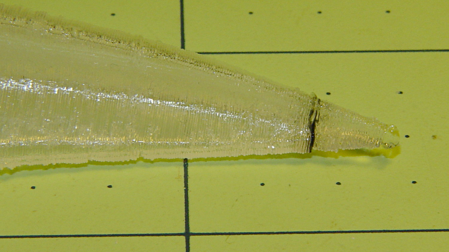
So I ran off a full-size version on the M2 for comparison:

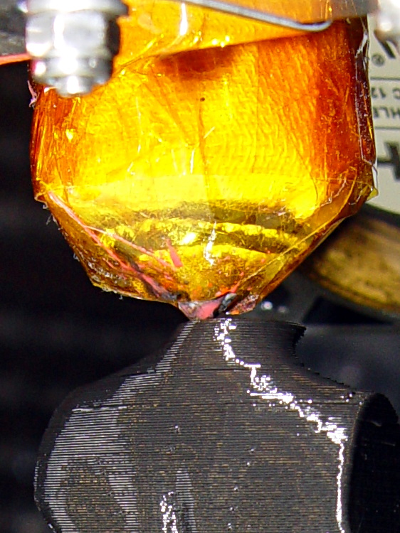
The extruder apparently contained a gobbet of black PLA, left over from the Pink Panther Woman, that managed to hang on inside until the very tip of the beak:
Close inspection found two black strands closer to the base of the printed parts:

The rear of the skull joins the front just behind the eye sockets, where the solid bottom layers make a visible contrast with the air behind the perimeter threads elsewhere. Refraction darkens some of the threads, but the two black patches stand out clearly.
If it weren’t natural PLA, those flaws wouldn’t be nearly so noticeable.
Were I doing this stuff for a living, I might dedicate a hot end (or an entire extruder) to each color and be done with it.
All in all, the printed quality is about as good as I could expect from a glorified glue gun.
The extreme slowdown while printing the tip of the beak pushed Pronterface’s remaining time estimate over the edge:

I’m not sure what the correct value should be …
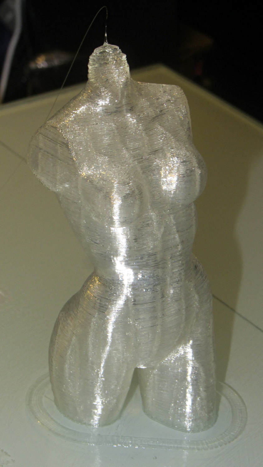
The Pink Panther Woman is my reference standard (*) for smooth perimeters and zitless filament retraction:
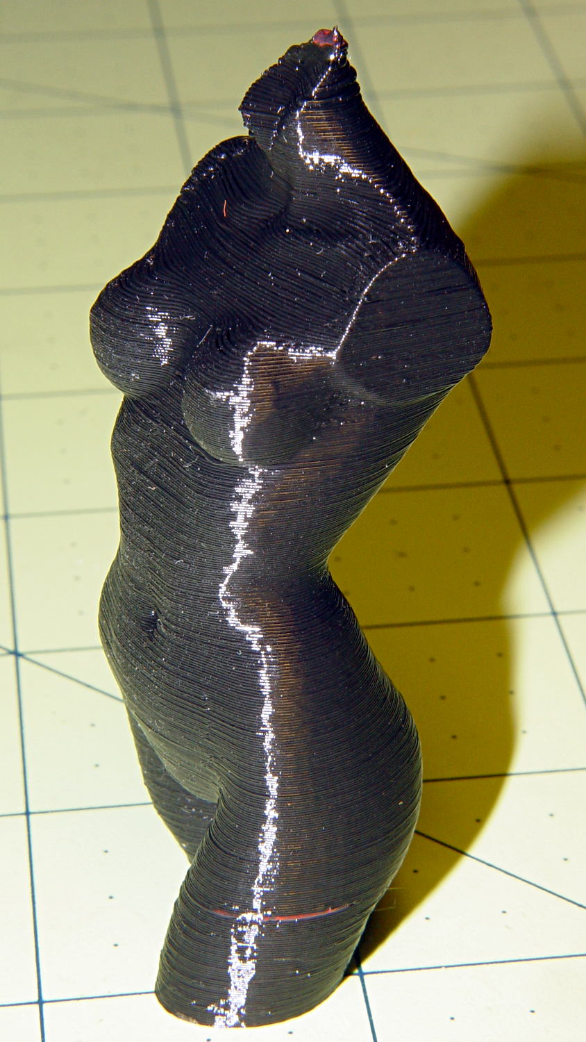
That’s vastly improved since the Thing-O-Matic’s last attempt:

Done in natural PLA, as it seems the previous version also walked off:
The attentive reader will note an odd red stripe on the left leg of the black PLA version. Here’s a closer look:

I had recently changed from red to black PLA and, as usual, purged the extruder with a few hundred millimeters of black filament, until it emerged pure black. Alas, I forgot to wipe the outside of the nozzle:
That red blob produced the red tab on the neck, as you can see if you look carefully at the first picture.
There are very few visible imperfections in either object: the state of DIY 3D printing is pretty good.
(*) Does anyone know of similar male figures suitable for this purpose? That torso seems to be about the extent of Thingiverse’s offerings.
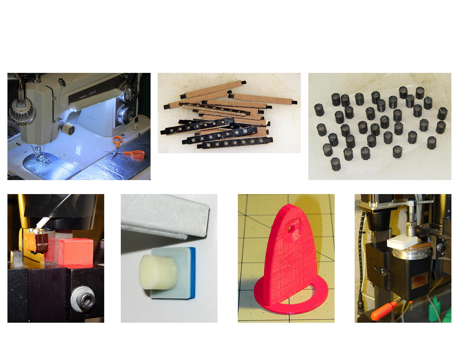
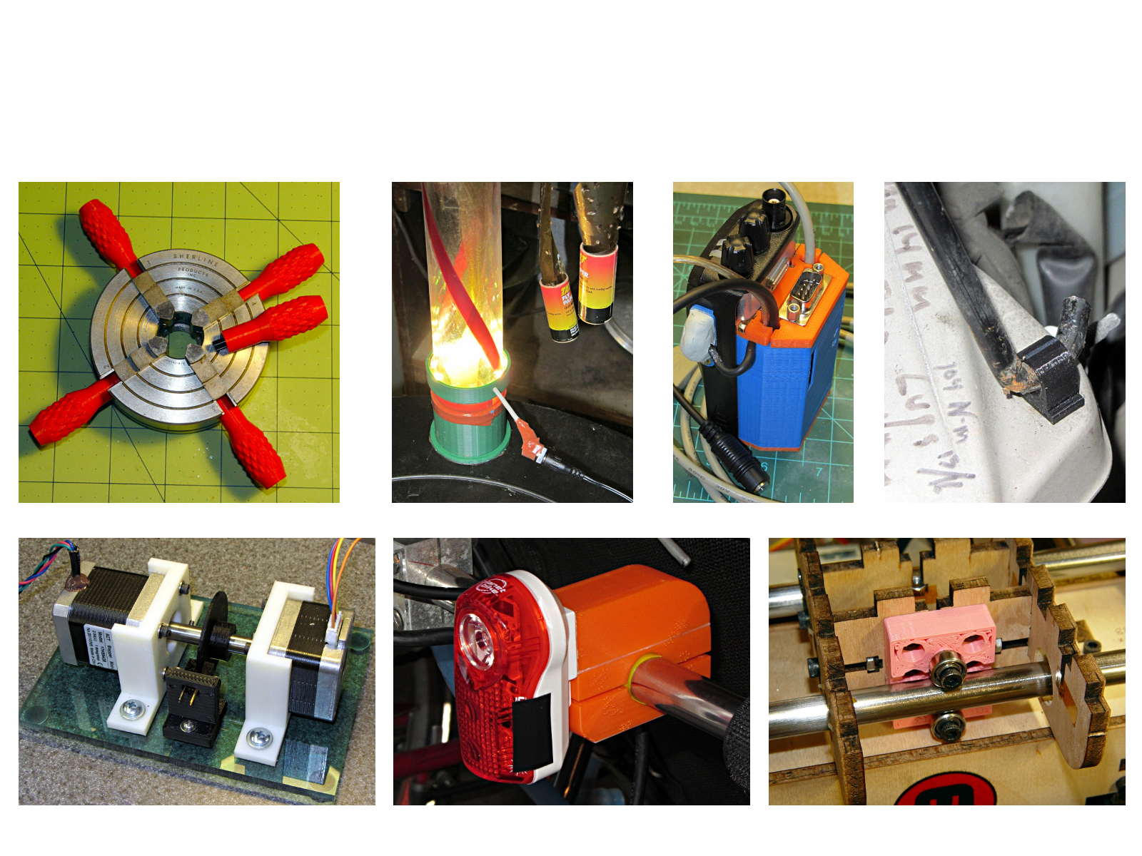
The whole reason I got a 3D printer in the first place was to make things that would otherwise be too difficult or tedious by hand or on a CNC mill. Most of the things I make look like brackets and I don’t do sculptures … this stuff solves problems!
Being able to go from “I need a part shaped like that” to holding the thing in my hand a few hours (or, for complex designs, days) later is empowering. Being able to adjust a dimension by changing the source code and “recompiling” to get a new part is wonderful.
These five slides from the presentation show my answers to the question “Why would anyone want a 3D printer?” Clicky for more dots.


You can find those and more by searching for OpenSCAD source code.
They go along with the sheets of solid models.
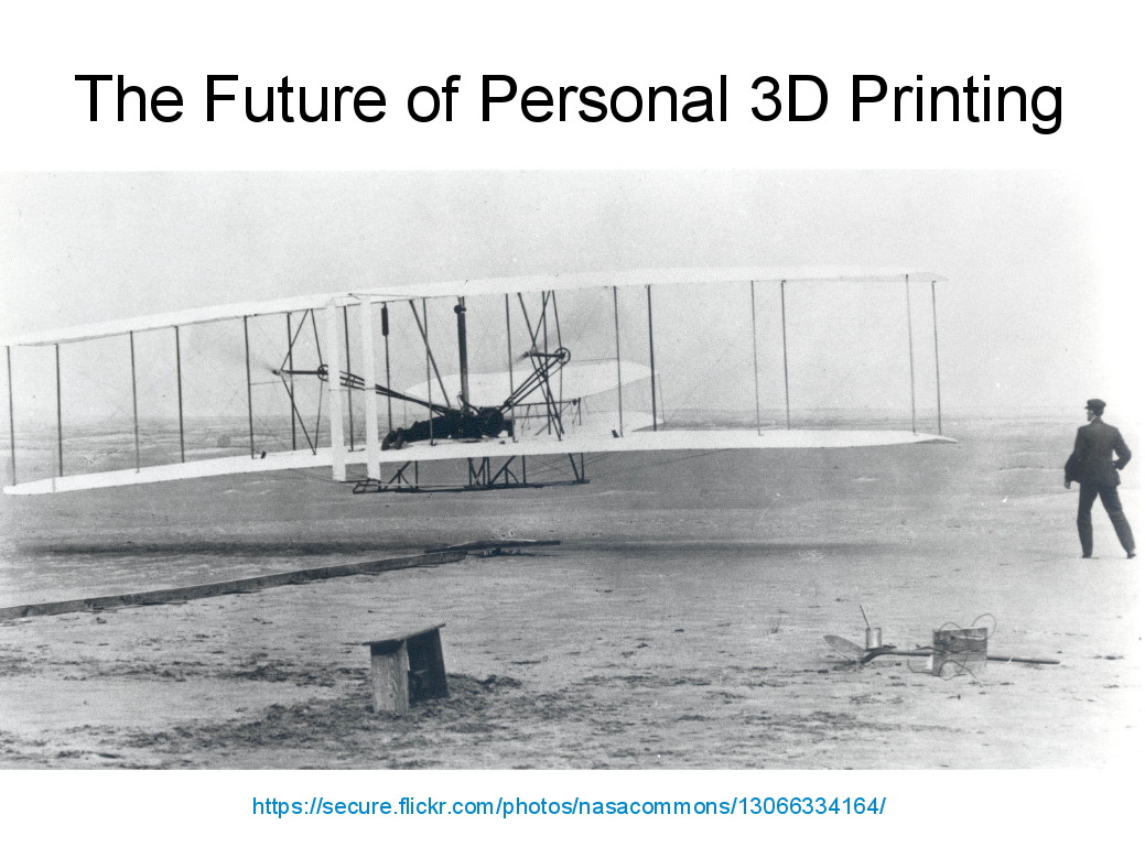
Herewith, the MHVLUG – 3D Printing Status 2104 slides (remember slides?) I’ll be using for my talk this evening at the MHVLUG meeting; you don’t get the audio track in the PDF, but the pictures may be informative.
If you believe everything you read, you might think personal 3D printing will go like this:

But it requires entirely too much of this:

Personal 3D printing requires that you take full control:

Not knowing the answers, I’ll still make some guesses about what lies ahead:
And I found the best tchotchkes ever:

See you there…
(The PDF has clickable links for those images, plus the 60-some-odd other slides. The plan: talk like an auctioneer for an hour!)
